Tippmann CUSTOM PRO User manual

Owner’s
Manual
Le Manuel du
Propriétaire
Manual
del Usuario
CUSTOM PROTM
CUSTOM PROTM RESPONSETM
CUSTOM PROTM WITH
E-TRIGGERTM
TIPPMANNTM
TP04500 Date06/05

WARNING
THIS IS NOT A TOY. MISUSE MAY CAUSE SERIOUS
INJURY OR DEATH. EYE, FACEAND EAR PROTECTION
DESIGNED FOR PAINTBALL MUST BE WORN BY THE
USER AND ANY PERSON WITHIN RANGE. WE
RECOMMENDAT LEAST 18YEARS OLD TO PURCHASE.
PERSONS UNDER 18 MUST HAVEADULT SUPERVISION
WHEN USING THIS PRODUCT. READ THE OWNER’S
MANUAL BEFORE USING THIS PRODUCT.
CE N’EST PAS UN JOUET. L’USAGE IMPROPRE PEUT
CAUSER LA BLESSURE SÉRIEUSE OU LA MORT. LA
PROTECTION POUR LES YEUX, LE VISAGE ET LES
OREILLES CONSTRUITE POUR LA BALLE DE PEINT
DOIT ÊTRE PORTER PAR L’UTILISATEUR ET N’IMPORTE
QUELLE PERSONNE DANS LE CHAMP DE TIR. NOUS
RECOMMENDONS QU’ ON A DIX – HUIT ANS AU MOINS
POUR L’ACHETER. LES PERSONNES SOUS L’ÂGE DE
DIX – HUIT ANS DOIVENT AVOIR LA SUPERVISION D’
UNADULTE QUAND ON EMPLOIE CE PRODUIT. IL FAUT
LIRE TOUT DE CE MANUEL AVANT DE L’UTILISER.
AVERTISSEMENT
F
R
A
N
Ç
A
I
S
E
N
G
L
I
S
H
ADVERTENCIA
ESTO NO ES UN JUGUETE. UN USO INAPROPIADO
PUEDE CAUSAR SERIAS HERIDAS O MUERTE. OJOS,
CARA Y OIDOS DEBEN SER PROTEGIDOS TODO EL
TIEMPO, CON LA PROTECCIÓN DISEÑADA PARA
PAINTBALL TANTO POR JUGADORES COMO POR
CUALQUIER PERSONA QUE ESTE EN EL RADIO DE
ALCANCE. RECOMENDAMOS AL MENOS 18 AÑOS
PARA LA COMPRA Y USO. LAS PERSONAS MENORES
DE 18 AÑOS DEBEN USAR ESTE PRODUCTO BAJO LA
SUPERVISIÓN DE UN ADULTO. ANTES DE USAR ESTE
PRODUCTO LEA EL MANUAL DEL USUARIO.
E
S
P
A
Ñ
O
L

F
R
A
N
Ç
A
I
S
E
N
G
L
I
S
H
WARNING
AVERTISSEMENT
SAFETY IS YOUR RESPONSIBILITY
ALWAYS KEEP
TRIGGER SAFETY
IN SAFE MODE
UNLESS FIRING
AS DETAILED IN
INSTRUCTIONS
ON PAGE 4.
ALWAYS KEEP
BARREL SLEEVE
INSTALLED WHEN
NOT IN SHOOTING
SITUATION AS
DETAILED IN
INSTRUCTIONS
ON PAGE 2.
READ, FAMILIARIZE
YOURSELF AND ANY
OTHER USER OF THIS
MARKER WITH THE
SAFETY INSTRUCTIONS
IN THIS MANUAL.
FOLLOW THESE
INSTRUCTIONS WHEN
USING, WORKING ON,
TRANSPORTING OR
STORING THIS MARKER.
SÉCURITÉ EST VOTRE RESPONSABILITÉ
IL FAUT
TOUJOURS
GARDER LA
MANCHE DU
CANON INSTALLÉE
QUAND ON NE
TIRE PAS COMME
DÉTAILÉ DANS LES
INSTRUCTIONS À
LA PAGE 2.
IL FAUT LIRE, VOUS
FAMILIARISER ET
TOUS LES AUTRES
UTILISATEURS DE
CE MARQUEUR AVEC
LES INSTRUCTIONS
DE SÉCURITÉ DANS CE
MANUEL. SUIVEZ CES
INSTRUCTIONS QUAND
VOUS UTILISEZ,
TRAVAILLEZ SUR,
TRANSPORTEZ, OU
ENTREPOSEZ CE
MARQUEUR.
IL FAUT TOUJOURS
GARDER LA
DÉTENTE DANS UNE
MODE DE SÉCURITÉ
SAUF QUAND ON
TIRE COMME
DÉTAILÉ DANS LES
INSTRUCTIONS À
LA PAGE 4.
1
E
S
P
A
Ñ
O
L
ADVERTENCIA
LA SEGURIDAD ES SU RESPONSABILIDAD
MANTENGA SIEMPRE
EL SEGURO DEL
GATILLO ACTIVADO
A MENOS QUE SE A
NECESARIO HACER
DISPAROS. INMEDIATOS
COMO SE VE EN LAS
INSTRUCCIONES
EN LA PÁGINA 4.
MANTENGA
LA FUNDA
DE
SEGURIDAD
INSTALADA
CUANDO NO
ESTE
HACIENDO
DISPAROS
COMO SE
ILUSTRA EN
LA PÁGINA 2.
EL PROPIETARIO Y
TODA PERSONA QUE
VA A USAR ESTE
MARCADORDEBELEERY
FAMILIARISARCE
CON
LAS ISTRUCCIONES DE
SEGURIDAD EN ESTE
MANUAL. SIGA LAS
INSTRUCCIONES DE
USO, MANTENIMIENTO,
TRANSPORTE Y
ALMACENAJE DE ESTE
MARCADOR.

WARNING
2
E
N
G
L
I
S
H
CORD
LENGTH
ADJUSTOR
BUTTON
2) PINCH CORD LENGTH
ADJUSTOR BUTTON AND
HOLD TO BACK OF GRIP AS
YOU PULL CORD THROUGH IT UNTIL ADJUSTOR IS SNUG
AGAINST BACK OF GRIP, THEN RELEASE BUTTON.
3) CHECK TO BE SURE YOU LEAVE ENOUGH CORD
ELASTICITY TO PULL CORD/ADJUSTOR UP OVER TOP OF
MARKER TO REMOVE BARREL SLEEVE FOR FIRING.
• EXCEPT WHEN YOUR MARKER IS IN USE, ALWAYS MAKE
SURE THAT THE TRIGGER SAFETY IS IN SAFE MODE (SEE
INSTRUCTIONS ON PAGE 4), AND THE BARREL SLEEVE IS
PROPERLY INSTALLED ON YOUR MARKER AS SHOWN BELOW.
1) SLIDE BARREL INTO SLEEVE AND LOOP CORD OVER TOP
OF RECEIVER AND POSITION AT BACK OF GRIP AS SHOWN
BELOW.
barrel
sleeve
barrel
sleeve
4) AFTER
CORD
LENGTH IS ADJUSTED,
LOCK CORD LENGTH BY TYING
A KNOT IN THE CORD AGAINST
THE BACK OF THE ADJUSTOR AS SHOWN.
BARREL SLEEVE INSTALLATION
WARNING
THIS IS NOT A TOY. MISUSE MAY CAUSE SERIOUS
INJURY OR DEATH. EYE, FACE AND EAR PROTECTION
DESIGNED FOR PAINTBALL MUST BE WORN BY THE
USER AND ANY PERSON WITHIN RANGE. WE
RECOMMENDAT LEAST 18YEARS OLD TO PURCHASE.
PERSONS UNDER 18 MUST HAVEADULT SUPERVISION
WHEN USING THIS PRODUCT. READ THE OWNER’S
MANUAL BEFORE USING THIS PRODUCT.

CONGRATULATIONS on your purchase of your TippmannTM
paintball marker. We believe our CUSTOM PROTM line of
markers be the most accurate and durable paintball markers
available, and proudly manufactured in the USA. All
TippmannTM CUSTOM PROTM markers will give many years of
dependable service if cared for properly.
Please take time to read this manual thoroughly and become
familiar with your CUSTOM PROTM model’s parts, operation,
and safety precautions before you attempt to load or fire
this marker. If you have a missing or broken part or need
assistance, please contact TippmannTM Consumer Relations
at 1-800-533-4831 for fast friendly service.
TABLE OF CONTENTS
Warning/Caution .................................................................... 2
Warning/Caution Barrel Sleeve Installation.......................... 2
Warning/Liability Statement................................................... 4
Safety is your Responsibility ................................................. 4
Safe Mode = Turning The Safety On ..................................... 4
Fire Mode = Turning The Safety Off ...................................... 4
Getting Started ....................................................................... 6
1. Prepare Marker for Air Supply Cylinder Installation...... 6
2. Air Supply Cylinder Installation ...................................... 6
3. Hopper ............................................................................ 7
4. Rate of Fire Adjustments and Troubleshooting ............. 7
5. Velocity Adjustment ........................................................ 7
6. Rear Sight Adjustment.................................................... 7
Schematic........................................................................12-13
Unloading Your Marker........................................................ 14
Air Supply Cylinder Removal .............................................. 14
Cleaning & Maintenance ..................................................... 14
Marker Disassembly ............................................................ 15
Repairing Air Supply Leaks ................................................. 16
Storage................................................................................. 16
Specifications ....................................................................... 17
Warranty and Repair Policy................................................. 18
Warranty or Repair Procedure ............................................ 18
Warranty Registration .......................................................... 18
3
2955 Adams Center Road, Fort Wayne, IN 46803 USA
P) 260-749-6022 • F) 260-749-6619
www.tippmann.com
TIPPMANNTM
E
N
G
L
I
S
H

• EXCEPT WHEN YOUR MARKER
IS IN USE, ALWAYS MAKE
SURE THAT THE BARREL SLEEVE
IS INSTALLED (SEE PAGE 2) AND
THE TRIGGER SAFETY
IS IN SAFE MODE WHICH
DISABLES THE TRIGGER.
TO TURN ON THE SAFETY (SAFE MODE): PUSH THE SAFETY
IN AS SHOWN ABOVE.
TO TURN SAFETY OFF (FIRE MODE): PUSH SAME BUTTON
ON OPPOSITE SIDE OF RECEIVER.
Warning/Liability Statement
This marker is classified as a dangerous weapon and is
surrendered by Tippmann Sports, LLC with the understanding
that the purchaser assumes all liability resulting from unsafe
handling or any action that constitutes a violation of any
applicable laws or regulations. Tippmann Sports, LLC shall
notbe liable for personalinjury, loss of propertyorlife resulting
fromtheuseof thisweaponunderanycircumstances,including
the intentional, reckless, negligent or accidental discharges.
All information contained in this manual is subject to change
without notice. Tippmann Sports, LLC reserves the right to
makechangesandimprovementstoproductswithoutincurring
any obligation to incorporate such improvements in products
previously sold.
If you as a user do not accept liability, Tippmann Sports, LLC
requests you do not use a Tippmann Sports, LLC marker. By
using this paintball marker you release Tippmann Sports, LLC
of any and all liability associated with its use.
4
Safety Is Your Responsibility!
The ownership of this weapon places upon you the total
responsibility for its safe and lawful use. You must observe
the same safety precautions as you would any firearm to
Safety IsYour Responsibility (continued on page 5)
E
N
G
L
I
S
H
FAMILIARIZE YOURSELF WITH SAFETY...
WARNING
PUSH SAFE
TRIGGER SAFETY ACTIVATION

assure the safety of not only yourself but everyone around
you. The user should at all times use caution when using this
marker. The sport of Paintball will be viewed and judged upon
your safe and sportsmanlike conduct. Always remember that
the game of Paintball can only survive and grow if it remains
SAFE!
• Do not load or fire this marker until you have completely read
thismanualandarefamiliarwithitssafetyfeatures,mechanical
operation and handling characteristics.
• Handle this and any marker as if it were loaded at all times.
• Keep your finger off the trigger until ready to shoot.
• Do not look down the barrel of a paintball marker. Accidental
dischargeintotheeyes may causepermanentinjuryordeath.
• Keep the marker on safe until ready to shoot.
• Keepthebarrelsleeve installedonmarkerwhennotshooting.
• Neverpointthemarkeratanythingyou do not intend to shoot.
• Never fire your marker at anything you do not intend to shoot
because there may be balls or foreign debris lodged in the
chamber, barrel and / or the marker valve.
• Do not shoot at fragile objects such as windows.
• Never fire your marker at personal property of others, the
paintball can stain the paint of automobiles and houses.
• Always keep the muzzle pointed down or in a safe direction,
even if you stumble or fall.
• Eye, face and ear protection designed specifically to stop
paintballs in the form of approved goggles and full face
maskshould bewornbytheuserandanypersonwithinrange.
• Nevershootataperson who is notprotectedbyeye,faceand
ear protection designed for paintball.
• Pressurize and load the marker only when the marker will be
immediately used.
• NOTE: Before storing or disassembling be sure to remove
paintballsandairsupply. Completelyemptythehopper, point
your marker in a safe direction, fire several times to be sure
there are no balls lodged in the chamber and/or barrel or air
left in the marker. Install barrel sleeve (see page 2).
• Store the marker unloaded and degassed in a secure place.
• Familiarize yourself with any warnings and instructions listed
on the air supply cylinder. Contact the air supply cylinder
manufacturer with any questions.
5
Safety Is Your Responsibility (continued from page 4)
Safety IsYour Responsibility (continued on page 6)
E
N
G
L
I
S
H

• Do not field strip or otherwise disassemble this marker while
it is pressurized with air supply.
• Dressappropriatelywhenplayingthegameofpaintball. Avoid
exposing any skin when playing the game of paintball. Even
a light layer will absorb some of the impact and protect you
from the paintballs.
• Keep exposed skin away from escaping gas when installing
orremovingairsupply cylinder or if the marker orairsupplyis
leaking. Compressedair, CO2,and nitrogen gasses are very
cold and can cause frostbite under certain conditions.
• Use only .68 caliber paintballs, never load or fire any foreign
objects.
• Avoid alcoholic beverages before and during the use of this
marker. Handling markers whileundertheinfluenceof drugs
or alcohol is a criminal disregard for public safety.
• Avoid shooting an opponent at point blank, 6 feet or less.
• Familiarize yourself with instructions listed on air supply
cylinder or adaptor. Contact the air supply cylinder or adaptor
manufacturerwithanyquestions.
• Always measure your marker’s velocity before playing
paintball and never shoot at velocities in excess of 300 feet
per second (see instructions on page 7).
6
Safety Is Your Responsibility (continued from page 5)
E
N
G
L
I
S
H
Getting Started (continued on page 7)
Getting Started
STEP 1) Prepare Marker for Air Supply Cylinder Installation
• ForModel:CustomProTM WithE-GRIPTM -Youmust firstinstall
battery(see instructions on page9before performing STEP 2.
• ForCustomProTM andCustomProTM ResponseTMgotoSTEP2.
STEP 2) Air Supply Cylinder Installation
• Do not pressurize a partially assembled paintball marker.
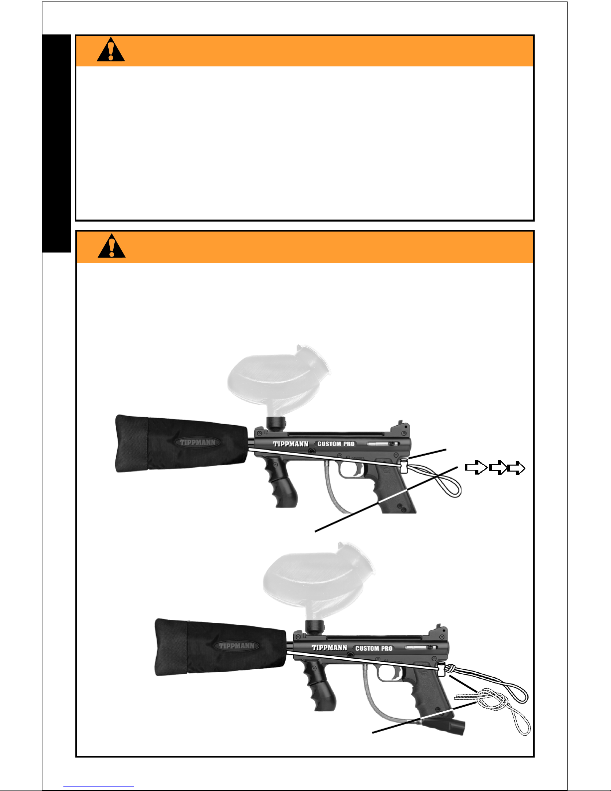
• First install barrel sleeve (see instructions on page 2).
• NextputtriggersafetyinSafeMode(seeinstructionsonpage4).
• Next you need to cock the marker by sliding the bolt handle
all the way back until it locks into place. Always keep marker
in the cocked position when air supply is attached to marker.
This will help prevent an accidental discharge.
• To install the air supply cylinder, lubricate the cylinder valve
o-ring with a little gun oil then insert the cylinder valve end
intothe air supplyadapterat the backendof the markergrip.
Twistthecylinderclockwiseintothemarkeruntilitstops. Adjust
the butt plate if necessary. Your marker is ready to fire once
youswitchtoFireMode from SafeMode. Ifthetankisfulland
youdo not heartheair supply engage,thepin valve couldbe
too short or the pin valve seal is damaged.

STEP 5) Velocity Adjustment
Each time you play paintball,
the velocity of your paintball
marker should be checked
with a chronograph, an
instrument for measuring
velocity, prior to playing
paintball to verify that the
marker’s velocity is set below
300 feet per second or less if
required by playing field.
To adjust the velocity use the 5/32” allen wrench included with
your marker. The velocity adjustment screw is located on left
sidereceiver. Toadjustthevelocitydown,turnthescrew inward
or clockwise. To turn the velocity up, turn the screw out or
counterclockwise. Do not remove velocity screw.
NOTE: You must turn the velocity screw all the way in before
doing any disassembly.
7
5/32” Allen Wrench
Velocity
Adjustment
Screw
E
N
G
L
I
S
H
Getting Started (continued from page 6)
STEP 3) Hopper
• Barrel Sleeve must be installed (see page 2) and safety in
Safe Mode (see page 4) before filling the hopper.
• Makesure that the feedelbowandhopperare clean and free
ofanysharp edges to keep paintballsfeedingintothemarker
smoothly.
• Install the hopper neck into the feed elbow of your marker
and tighten the hopper down with a 3/16” allen wrench.
NOTE: Do not overtighten or the elbow may break. With the
barrel sleeve installed and safety in Safe Mode, you are now
ready to load your hopper with paintballs. Fill hopper and
only remove barrel sleeve and turn off the safety when ready
to shoot.
STEP 6) Rear Sight Adjustment
If your paintball is hitting low, slide the rear sight back towards
rear of marker. Do the opposite if paintball is hitting high.
STEP 4) Rate of Fire Adjustments and Troubleshooting
• For RESPONSETM marker - complete Tuning The Response
TriggerRateofFireinstructionson page 8 then goto STEP 5.
• For E-TRIGGERTM marker - complete E-GRIP Tuning and
Operating Instructions on page 9.
• For CUSTOM PROTM marker - Go to STEP 5.

counterclockwise to increase
rateoffiretothe
desiredspeed.
clockwise
to slow the
rate of fire
With a screwdriver, turn the Flow ControlAdjustor
Tuning The RESPONSETM Trigger Rate of Fire
Tuning - Troubleshooting B:
Ifthe triggerremainseasytopullafteradjustingtheflowcontrol,
there may be a leak in the system. Double check installation
makingsureallfittingsare tightando-ringsareproperlyseated.
If you need to disassemble to check that all fittings are tight
and o-rings are properly seated, do not disassemble this
marker while it is pressurized with air, follow disassembly /
assembly instructions on page 15.
If a problem still exists, call TippmannTM Service Department at
1-800-533-4831.
Tuning - Troubleshooting A:
If tuning the ResponseTM trigger produces little or no response
in the rate of fire, reset the Flow Control as follows:
1) With marker properly unloaded (see page 14), begin
adjusting rate of fire by turning flow control clockwise
completely. Donotovertightenordamage will occur. Inasafe
directionfire 2 to4shots. Trigger should become veryhardto
pull or even unable to be pulled. If this occurs, the response
trigger system is functioning properly. Go to step 2. If it does
not occur, go to Troubleshooting B.
2) Nowwhilefiring inasafedirectionwithmarkerstillunloaded,
slowly turn the flow control adjustor counterclockwise until
desired rate of fire is achieved.
NOTE: To disable the ResponseTM System, remove
the universal 900fitting attached to the power tube/
valve and replace it with the shut off plug.
TM
E
N
G
L
I
S
H
8

9
E
N
G
L
I
S
H
STEP1: Prepare themarkerfordisassembly.
To do so, first follow the unloading and air supply removal
instructions on page 14 and never disassemble a marker that
is under pressure.
STEP2:Remove Battery Clip/old battery(from marker).
1) Remove left grip (2 bolts).
2) Carefully work battery out of receiver cutout bringing non-
connected end out first. As you remove battery from receiver,
do not rip wires off of internal components.
3) Carefully remove old battery from battery clip connector.
E-TRIGGERTM Battery Installation or Replacement
Before installing air supply, install 9 volt battery (not included).
E-TRIGGERTM Tuning and Operating Instructions (continued onpage10)
STEP3: Install new battery.
1)Attach 9v battery to battery connector and
be sure wires lay flat inside the cutout area of
receiver (as shown on page 11).
2) Carefully tilt and insert your new battery, wire
attached end first, into receiver as shown.
3) Reinstall left receiver grip with 2 grip bolts.
TURNING ON = TheE-TRIGGERTM automatically turnson
when you pull the trigger.
TURNING OFF = TheE-TRIGGERTM automaticallyturns off
after 10 minutes or so of inactivity.
E-TRIGGERTM Tuning and Operating Instructions
Familiarizeyourself with and followtheseinstructions to select
the firing mode of your choice from the Firing Mode Setting -
Firing Response Description options on page 10.
Selecting Firing Mode
Mode Adjustment - Top Access Opening
• With screwdriver, turn the Mode Adjustment switch
to select desired firing mode setting on page 10.
Selecting Rate of Fire
Rate Adjustment - Lower Access Opening
• Turn the Rate of Fire
Switch clockwise
to increase the
rate of fire.
• Turn the Rate
of Fire Switch
counterclockwise
to slow the rate of fire.
Battery installation is complete.

E-TRIGGERTM - Mode Settings / Firing Response
Firing Mode Setting .Firing Response Description:
0=NOOPERATION .......No response.
1=SEMIAUTO ..............Fires one shot for each pull of the trigger.
2=NOOPERATION .......No response.
3 =AUTO RESPONSE....Fires one shot for each pull or release of
the trigger. If the trigger is held for an extended period, when the
trigger is released no shot is fired.
4=NOOPERATION .......No response.
5 = FULLAUTO ..............Fires shots repeatedly as long as the
trigger is held.
6=NOOPERATION .......No response.
7 = 3 SHOT ....................Fires either a 3 shot burst when the
trigger is held or if trigger is released before 3 shot cycle is
complete - firing stops at that point of cycle.
8=NOOPERATION .......No response.
9 = TURBO .....................Fires one shot for each pull of the trigger
until the time between trigger pulls is below .25 seconds - it then
goes to one shot for each pull or release of the trigger.
Problem: If you pull the trigger and marker does not fire.
1) Check to be sure safety is off.
2) Make sure sufficient air supply is hooked up to marker.
3)Firing Mode maybeset to “=NOOPERATION”.
With screw driver, turn Mode adjustment, access through top
hole in lower receiver, turn 1 position (click) try trigger again.
4)Batterymaybe disconnected -checkbatteryclipconnection.
5) Battery may be bad - replace battery.
6) Internal wire may be disconnected. Inspect wire connec-
tions inside lower receiver. To do so, first follow the unloading
and air supply removal instructions on page 14 and never
disassemble a marker that is under pressure. Remove left
receiver half as outlined on page 15, then visually inspect in-
ternal wires for disconnected wire end(s). When replacing left
receiver half, be sure wires are positioned in cutout areas so
wires are not pinched or sheared and the armature pin moves
freely (follow instructions on page 11).
If a problem still exists, call TippmannTM Service Department at
1-800-533-4831.
E-TRIGGERTM Troubleshooting
E-TRIGGERTM Tuning and Operating Instructions (continuedfrom page 9)
E-TRIGGERTM Troubleshooting (continued on page11)
10

1) Place solenoid /
armature into position
in right receiver.
InsertMagnetin slot
below armature as shown.
2) Carefully align and insert
computer board into slot.
3) Place trigger switch on two
pins of right receiver half.
4) Insert capacitor in slot.
5) Route wires in cutout areas to
lay flat under armature pin and battery and not be pinched
when receiver halves are reassembled.
6) Insert armature pin into 2 slots so it moves freely.
7) Double check that all parts are in place as shown.
E-TRIGGERTM InternalParts PositionedforReassembly
Do not operate sear
tripper assembly
uninstalled as
solenoid/armature
may pinch you.
E-TRIGGERTM Reassembling Receiver Halves
1)Doublecheck that all other parts:FrontSight,FrontSitePin,
Front Sight Spring, Ball Latch, Front Bolt, Linkage Arm, Rear
Bolt, Drive Spring & Guide Pin, Buffer O-ring, End Cap, Rear
Sight and TankAdapter Nuts are place.
2) Place battery connector through left receiver half as you
replace left half on right half, don't pinch wires.
3) Make sure halves fit flush and magnet fits into left receiver
halfslotsoitdoesnot break. For ease of installationtightenthe
boltoverthe trigger first. Next reinsert front grip,itgetslongest
bolt, and tighten 5 remaining bolts.
4) Reinstall tank adapter and reinstall barrel.
5)Attach 9v battery to battery connector and be sure wires lay
flat inside the cutout area of receiver, as shown above.
6) Carefully tilt and insert battery,
wire attached end first, into receiver.
7) Reinstall left receiver grip with 2 bolts.
Reassembly is complete.
You are now ready to tune the E-TriggerTM
rate of fire and set the mode of fire as
outlined in tuning instructions on page 9.
E-TRIGGERTM Troubleshooting (continuedfrom page 10)
11

12
E
N
G
L
I
S
H
CUSTOMPROTM
Basic Parts List Custom ProTM ResponseTMParts (page 17)
Custom ProTM with E-TriggerTMParts (page 17)

13
E
N
G
L
I
S
H
WARNING
DO NOT FIELD STRIP OR OTHERWISE DISASSEMBLE
THIS MARKER WHILE IT IS PRESSURIZED WITH AIR.
TIPPMANNTM
1-800-533-4831
www.tippmann.com

Air Supply Cylinder Removal
To remove a charged air supply cylinder, turn the cylinder
approximately 3/4 of a turn counterclockwise or out. This allows
the air supply pin valve to close so that no air will enter the
marker. Point the marker in a safe direction and fire the
remaining gas in the marker by pulling the trigger until the
marker stops firing. This may take 4-5 shots.
If your marker keeps firing after you have turned the tank 3/4 of
a turn, the tank pin valve has not closed yet and you may have
to turn the tank counterclockwise a little further.
If you turn the tank 3/4 of a turn and it begins to leak before you
pullthetriggeryouhaveturnedit too far and may have damaged
the tank o-ring.
Because of the variances in tank valve parts, each tank varies
slightly on exactly how far it should be turned. If this process
does not work the tank pin valve could be too long.
NOTE: Before storing or disassembling be sure to remove
paintballs and air supply. Completely empty the hopper, point
your marker in a safe direction, fire several times to be sure
there are no balls lodged in the chamber and/or barrel or air
left in the marker. Install barrel sleeve (see page 2).
Cleaning & Maintenance
To reduce the chance of accidental discharge: First follow
unloading and air supply removal instructions above and never
disassemble a marker that is under pressure.
• Follow warnings listed on the air supply cylinder for handling
and storage.
• Familiarize yourself with instructions listed on air supply
cylinder or adaptor. Contact the air supply cylinder or
adaptor manufacturer with any questions.
• Do not use any petroleum based cleaning solvents.
• Do not use any cleaning solvents that come in aerosol cans.
NOTE: Petroleum based products and aerosol products can
damage your markers’ o-rings.
• To clean your paintball marker use a damp towel with water
to wipe off paint, oil, and debris. We recommend using
TippmannTM marker oil or other premium gun oil to maintain
your marker in good working condition. Re-oil with a few
drops to the front bolt o-ring and rear bolt. We also
14
Unloading Your Marker
To unload your marker remove the hopper or completely empty
the hopper. Then, point your marker in a safe direction and fire
severaltimestobe sure there are noballslodgedin the chamber
and / or barrel. Install barrel sleeve (see page 2).
IMPORTANT: Do not uncock your marker as uncocking your
marker may push a ball into the chamber or down into the
barrel in which case the ball will be hidden from view.
E
N
G
L
I
S
H
Cleaning and Maintenance (continued on page 15)

15
E
N
G
L
I
S
H
To remove the left-side receiver, unscrew bolts (4-9) receiver
connection bolts. Then carefully lift the left-side receiver to
access the internals.
NOTE: The Safety will stay on the left-side receiver and should
be reassembled the same way.
Once inside, pull the end cap out to remove the guide pin
and drive spring. These parts must be removed before the
bolt handle will release. Disconnect the linkage arm from
the rear and front bolts. Slide the front bolt off the power
tube and check the o-ring. Clean and oil the o-ring or if
damaged, replace with a new one. Do the same with the
rear bolt o-ring.
Field Stripping / Receiver Disassembly (continuedon page16)
Marker Disassembly
First follow unloading and air supply removal instructions on
page 14. Do not pressurize a partially assembled paintball
marker. Putthemarkerintheuncockedposition. Ifyourmarker
is cocked, hold the bolt handle while pulling the trigger which
will uncock the marker.
NOTE: The barrel (1) and adapter bolts (2-3) must be removed
first. Next, turn the velocity screw in until it stops.
Longest
bolt
goes in #6
front grip
when reassembling
Total Six Receiver
Connection Bolts
recommend using TippmannTM marker oil or other premium
gun oil on the barrel o-ring and air supply valve o-ring.
• To clean the barrel. Depress front sight and tip out feed
elbow. Insert metal tab of cable squeegee into breach, then
pull squeegee through barrel to remove debris.
Cleaning and Maintenance (continued from page 14)

Power tube and valve removal.
NOTE: Donot remove thegasline fitting unlessitis leaking or
you need to replace the valve. If you should do so you will
need some teflon tape or paste to reinstall it.
Field Stripping / Receiver Disassembly (continuedfrom page15)
• First, you need to complete Marker / Receiver Disassembly
Instructions on page 15.
16
E
N
G
L
I
S
H
• Removal: To release the power
tube and valve, unscrew the
two valve lock bolts on the
outer right-side receiver.
• Installation: Apply red loctite to
bolts threads and do not over
tighten valve lock bolts and
strip threads when reinstalling.
Storage
Before storage unload and remove air supply (see page 14).
Then install Barrel Sleeve (see page 2) and put your marker in
Safe Mode (see page 4). You should store your marker in a dry
area. Before storing your marker make sure that the marker is
cleaned and oiled (see cleaning and maintenance on page
14) so that it does not rust. Store your marker with the bolt in
the forward position, uncocked.
12
12
Valve Lock
Bolts
Valve removal from power tube: If itisnecessarytoremovethe
valve, use a wrench to slowly unscrew the gas line fitting. Once
thefittingisout,thevalvewillslideoutthebackofthepowertube.
NOTE: Checktheexternalvalve o-ringatthistime. Iftheo-ring
is damaged your marker will not function correctly.
Reinstalling valve: Insert valve into power tube, align holes
and add teflon tape or paste to gas line fitting threads, slowly
screw into valve and snug with wrench.
Repairing Air Supply Cylinder Leaks
The most common leak occurs from a bad air supply valve
o-ring. To replace a valve o-ring you must first remove the bad
o-ring and then install a new one. This o-ring is located on the
tip of your air supply valve. The best valve o-rings are made of
urethane. The urethane o-rings are not affected by high air
supply pressures. These may be purchased from TippmannTM
or your local paintball dealer.
NOTE: If new valve o-ring does not resolve air supply leak, do
not attempt to repair air supply cylinder. Contact Tippmann
Sports, LLC or your local paintball dealer.
Storage (continuedonpage 17)

17
E
N
G
L
I
S
H
Specifications
Model Basic ................................TippmannTM CUSTOM PROTM
Caliber ................................................................................. .68
Action .......................... Semi-Automatic (open bolt blow-back)
Power/Air Supply ...................... compressed air, nitrogen or CO2
Hopper Capacity ............................................... 200 Paintballs
Cycle Rate ..................................................8 shots per second
Standard Barrel Length ....................................................... 11”
Overall Length (with standard barrel & no tank) ................. 21”
Weight (without tank) .....................................................2.9 lbs.
Effective Range ............................................................ 150+ ft.
Velocity ..................... Always measure your marker’s velocity
before playing paintball and never shoot at velocities in
excess of 300 feet per second (see instructions on page 7).
Model Specific ....TippmannTM CUSTOM PROTM RESPONSETM
Cycle Rate ............................................... 15 shots per second
Weight (without tank) ...................................................3.05 lbs.
Model Specific..TippmannTM CUSTOM PROTM WITH E-TRIGGERTM
Cycle Rate............................................... 17 shots per second
Weight (without tank) ...................................................3.19 lbs.
When removing your marker out of storage make sure Barrel
Sleeve is installed (see page 2) and safety is in Safe Mode
(see page 4). You should re-oil the rear bolt and the front bolt
o-ring before use.
Model Specific Parts Not Shown on CUSTOM PROTM schematic.
CUSTOM PROTM RESPONSETM CUSTOM PROTM WITH E-TRIGGERTM
20-26 ShutOff Plug
20-07 Flow Control 900Fitting
20-18 Flow Control Hose
20-03Flow
ControlValve
20-07900Fitting
20-05 Cylinder Hose
20-04 Cylinder 900Fitting
20-20NCylinder
02-91Armature Pin
02-90Sear Tripper
Assembly
TA05014
Magnet
(Armature
fits inside
bottomof
solonoid)
02-88
SearSpring
TA01135
Sear
Storage (continued from page 16)

WARRANTY AND REPAIR POLICY
WARRANTY OR REPAIR PROCEDURE
If you should encounter any problems with your marker and
you have aftermarket parts on your marker, please test it with
the original stock parts before sending it in.
Always unload and remove air supply before shipping a marker.
Do not ship your air supply tank if it is not completely empty.
For warranty and non-warranty repair:
1. Ship or deliver your product(s) to:
Tippmann Sports, LLC
2955 Adams Center Road
Fort Wayne, IN 46803
2. Postage or delivery charges must be prepaid.
3. Include a brief statement regarding the requested repair,
your name, return address and telephone number where
you can be reached during normal business hours, if possible.
Our policy is to complete the necessary repair work within 24
hours and return it to you via regular ground UPS. If you wish to
have it returned using a faster service, you can request for
NEXT DAY AIR UPS OR SECOND DAY AIR UPS. You will be
charged for this service and must include your credit card
number with the expiration date. Your card will be charged the
difference in additional cost over regulargroundshippingservice.
Tippmann Sports, LLC warrants that this product is found free
from defects in materials and workmanship for a period of 1
year from the original date of purchase by the initial owner/
purchaser. This warranty does not apply to defects discovered
after purchase which were caused by the unauthorized
modifications and alterations of our product. Tippmann Sports,
LLC will repair or replace, without charge, any of its markers that
have failed through defect in material or workmanship. Tippmann
is dedicated to providing you with the ultimate paintball marker
and the quality support necessary for satisfactory play.
18
E
N
G
L
I
S
H
WARRANTY REGISTRATION
Register your marker either:
1. On line at www.tippmann.com.
2. Complete attached registration card and mail to the above
address.
This manual suits for next models
2
Table of contents
Other Tippmann Fitness Equipment manuals
Popular Fitness Equipment manuals by other brands

Skandika Fitness
Skandika Fitness Rower CAMBRIDGE Setup and user's manual

Crivit
Crivit 292878 Operation and safety notes

First Degree Fitness
First Degree Fitness Fluid Rower FDR-02 owner's manual

NordicTrack
NordicTrack Spacesaver SE7i user manual

MAYHEM STRENGTH
MAYHEM STRENGTH Bottom Drive Belt Squat Assembly instructions

Weider
Weider 8920 user manual

BH FITNESS
BH FITNESS G6485 quick start guide

Align-Pilates
Align-Pilates M2-Pro Reformer Assembly instructions & user manual

Titanium Strength
Titanium Strength HM3360 owner's manual

Precor
Precor move beyond S3.15 Assembly instructions

cefar
cefar IFC operating instructions

Weider
Weider PRO 9925 user manual