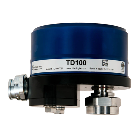
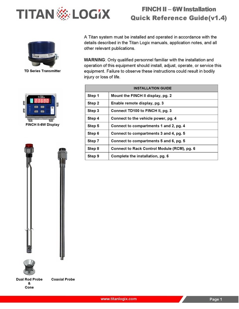
Titan Logix FINCH II User manual

PROPRIETARY INFORMATION
The Information disclosed herein contains proprietary rights of Titan Logix Corp.
Neither this document nor the information disclosed herein shall be reproduced or
transferred to other documents, or used or disclosed to others for manufacturing
purposes, or for any other purpose except as specifically authorized in writing by Titan
Logix Corp.
FINCH II Installation and Operation Manual
TPM 010, Rev 7.0

FINCH II Installation & Operation Manual
TPM 010, Rev 7.0
www.titanlogix.com Pg. 2
Contents
1Introduction..................................................................................................................................................... 5
1.1 About This Manual..................................................................................................................................5
1.2 Disclaimer ...............................................................................................................................................5
1.3 FINCH II..................................................................................................................................................5
2Installation....................................................................................................................................................... 5
2.1 Pre-Installation Requirements.................................................................................................................5
2.2 Titan System Installation Workflow .........................................................................................................6
2.3 Titan System Installation Steps...............................................................................................................6
2.4 FINCH II Electrical Wiring Instructions....................................................................................................8
2.5 Basic Single or Dual Compartment Installation (FINCH II-W) ................................................................9
2.5.1 FINCH II-W Installation Overview ......................................................................................................9
2.5.2 Mount the FINCH II-W Display.........................................................................................................10
2.5.3 Enable Remote Display ...................................................................................................................10
2.5.4 Connect TD 100 to FINCH II-W .......................................................................................................11
2.5.5 Connect to Vehicle Power................................................................................................................11
2.5.6 Connect to Compartments 1 & 2......................................................................................................12
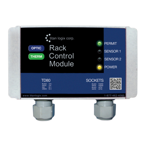
2.5.7 Connect the RCM (Optional)............................................................................................................12
2.5.8 Complete the Installation..................................................................................................................12
2.6 Multi Compartment Installation (FINCH II-6W)......................................................................................16
2.6.1 Mount the FINCH II-6W....................................................................................................................16
2.6.2 Enable Display.................................................................................................................................17
2.6.3 Connect TD100 to FINCH II-6W ......................................................................................................17
2.6.4 Connect to Vehicle Power................................................................................................................17
2.6.5 Connect to Compartments 1& 2.......................................................................................................17
2.6.6 Connect to Compartments 3 & 4......................................................................................................18
2.6.7 Connect to Compartments 5 & 6......................................................................................................19
2.6.8 Connect to Rack Control Module (Optional) ....................................................................................19
2.6.9 Complete the Installtion ...................................................................................................................19
2.7 FINCH II Display & High-Level Shutdown Electrical Wiring Instructions...............................................20
2.8 Single Compartment Crude Oil Trailer with On-board Pump or Bottom Loading Valve Control ...........23
2.8.1 Electrical Installation for high level shutdown system ......................................................................24
2.9 Installation Test & Calibration ...............................................................................................................26
2.9.1 TD100 Basic Operation Tests..........................................................................................................26
2.9.2 TD100 System Testing and Verification...........................................................................................26
3 FINCH II Configuration ................................................................................................................................. 28
3.1 FINCH II Failsafe ..................................................................................................................................28
3.1.1 Single/Dual Compartment Failsafe Configuration (FINCH II-W) ......................................................28
3.1.2 Multicompartment Failsafe Configuration (FINCH II-6W).................................................................28
3.2 FINCH II Alarms....................................................................................................................................28
3.3 FINCH II Relays....................................................................................................................................29

FINCH II Installation & Operation Manual
TPM 010, Rev 7.0
www.titanlogix.com Pg. 3
3.3.1 Configuring Relay Assignments and Alarming States......................................................................29
4 System Operation......................................................................................................................................... 30
4.1 Start Up.................................................................................................................................................30
4.2 Introduction to Operation ......................................................................................................................30
4.3 FINCH II Operator Interface..................................................................................................................30
4.4 Offset Measurement .............................................................................................................................32
4.4.1 Offset Measurement Description.....................................................................................................32
4.4.2 How to measure Offset ...................................................................................................................32
4.4.3 Programming the TD100.................................................................................................................33
4.5 Modes of Operation ..............................................................................................................................34
4.6 Alarms...................................................................................................................................................35
4.6.1 Spill Alarm.......................................................................................................................................35
4.6.2 Fill and Fall Alarm ...........................................................................................................................35
4.6.3 Set Fill or Fall Alarm........................................................................................................................35
4.6.4 High High Alarm..............................................................................................................................36
4.6.5 Fail Alarm........................................................................................................................................36
4.6.6 Disabling the 2 LO Message...........................................................................................................36
4.7 Alarm Settings.......................................................................................................................................37
4.7.1 Coax Probe Alarm Settings Diagrams .............................................................................................37
4.7.2 Dual Rod Alarm Settings Diagrams ...............................................................................................38
4.7.3 Configuring the Alarms ...................................................................................................................39
5 Troubleshooting........................................................................................................................................... 39
5.1 Overview and General Techniques.......................................................................................................39
5.1.1 Error Codes......................................................................................................................................39
5.1.2 High Level Shutdown System Troubleshooting ..............................................................................40
5.2 TD100 System Specific Troubleshooting..............................................................................................42
5.2.1 Common System Wiring and Component Failures .........................................................................42
5.2.2 Common System Installation Problems ...........................................................................................48
5.3 Alternate TD100 System Troubleshooting ............................................................................................51
5.4 FINCH II Relay Tests ............................................................................................................................52
5.4.1 Fill or Fall Alarm Test ......................................................................................................................52
5.4.2 High level shutdown System Test...................................................................................................52
5.5 TD100 System Test & Verification Checklist ..........................................................................................53
6Graphical Glossary of Terms ........................................................................................................................ 53
6.1 Dual Rod Probe Truck and Trailer Installation ......................................................................................53
6.2 Coaxial Probe Truck and Trailer Installation .........................................................................................54
7 Technical Reference ......................................................................................................................................... 54
7.1 Installation/Wiring Instructions: .............................................................................................................54
7.2 Terminal Block Descriptions:.................................................................................................................54
7.3 Relay Assignments: ..............................................................................................................................56

FINCH II Installation & Operation Manual
TPM 010, Rev 7.0
www.titanlogix.com Pg. 4
7.4 Relay Alarming States ..........................................................................................................................57
7.5 SVBus Connections: .............................................................................................................................57
7.6 Remote Input Connections:...................................................................................................................57
7.7 RS232 Connections:.............................................................................................................................57
7.8 Maximum Relay Capacity: ....................................................................................................................57
7.9 Hardware Configuration Settings: .........................................................................................................57
7.9.1 Rotary Switches:..............................................................................................................................57
7.9.2 Dip Switches ....................................................................................................................................58
7.9.3 Push Button Switches ......................................................................................................................58
8 FINCH II and TD100 Transmitter Programming Cable Adapter.................................................................... 59
9Technical Specifications ............................................................................................................................... 60

FINCH II Installation & Operation Manual
TPM 010, Rev 7.0
www.titanlogix.com Pg. 5
1 Introduction
1.1 About This Manual
This document will describe the recommended procedure for installing a FINCH II Display. A Titan Logix system
must be installed and operated in accordance with the details described in the Titan Logix manuals, application
notes and all other relevant publications.
- This Manual (TPM010) is specific to the FINCH II Installation and Operation.
- For complete information on the TD100, please refer the TD100 Product Manual, TPM 057.
- For complete information on the RCM, please refer to the RCM Product Manual, TPM 007.
1.2 Disclaimer
The information in this document is subject to change without notice. Titan Logix Corp. makes no
representations or warranties with respect to the contents hereof.
WARNING
Only qualified personnel familiar with the installation and operation of this equipment should
install, adjust operate, or service this equipment. Failure to observe these instructions and
applicable safety and electrical regulations could result in bodily injury or loss of life.
Only replace with sand filled fuses of same type and rating.
EXPLOSION HAZARD –Substitution of components may impair suitability for Class 1, Division 2.
EXPLOSION HAZARD –Do not connect or disconnect equipment or replace fuse unless power has
been switched off and / or the area is known to be non-hazardous.
EXPLOSION HAZARD –Batteries must only be changed in an area known to be non-hazardous.
To maintain a Class 1, Division 2 rating, each relay must only be supplied with
8-30VDC / 3.3A max transient protected power.
1.3 FINCH II
The FINCH II Display is weather-proof device for internal or external use.
It provides bright LED numeric display of volume information, alarms, and
system error codes from the TD80 and the TD100 transmitter. Various alarm
and error conditions are detected by the transmitter and display. These alarm
states control four internal relays for alarming, high level shutdown and low-
level prevention.
The FINCH II contains high power relays to directly control a bottom loading
solenoid valve or control of an onboard loading pump.
- FINCH II-W provides Rack control (RCM)support for 1 or 2 compartments.
- FINCH II-6W provides Rack control (RCM) support for up to 5 compartments.
2 Installation
2.1 Pre-Installation Requirements
1. When choosing a location to install the Titan Logix system, the following guidelines must be followed:
- Appropriate industry, national, provincial/state, and local codes.
- Fuses and components are appropriate for the area classification.
2. The tank is completely drained of liquid and vapour free.
3. No drilling or welding to the tank and frame without first consulting with the tank manufacturer.
4. This manual will provide information about:

FINCH II Installation & Operation Manual
TPM 010, Rev 7.0
www.titanlogix.com Pg. 6
2.2 Titan System Installation Workflow
Installation Workflow
1
Program the TD100 Transmitter and FINCH II Display
2
Install the TD100
3
Mount the FINCH II Display
4
Mount the Alarm Accessories (optional), including the RCM
5
Inspect the Mechanical Installation
6
Install the Electrical Wiring
7
Set and Verify the Correct Switch Settings
8
Confirm Fuses Installed with Correct Type and Rating
9
Perform the Basic Operation Test
10
Verify TD100 Transmitter Programming Information
11
Set the FILL or FALL Alarm Level Volume
12
Perform the TD100 System Test and Verification
13
Perform Offset Measurement
Table 2-2 Installation Workflow
2.3 Titan System Installation Steps
1. Program the TD100 and FINCH II Display
The TD100 must be programmed before use. Programming may be done at the factory when
purchased, programmed by the customer prior to installation or after installation on the vehicle when
necessary.
The FINCH II display may need to be programmed. Alarms are assigned to internal relay actions for
flexible alarm annunciation and high-level shutdown. The factory settings are appropriate for most
applications. Programming may be done by prior to installation or after installation on the vehicle when
necessary.
2. Install the TD100 as indicated in the TD100 Installation and Operation manual. (TPM 057)
3. Mount the FINCH II display in a suitable location (preferably in a weatherproof enclosure)
4. Optional Alarm accessories mounting
(Lights, Horns, Alarm Acknowledge push button)
5. Inspect the Mechanical Installation
6. Electrical Installation
- The TD100 transmitter is provided with a 50’/ 75’ cable kit. It is recommended to use the kit with
included sealing fitting for connection to the FINCH II display.
- All electrical grounding is to the vehicle or trailer electrical ground connection and not to the chassis.
- Wire splices should be made inside a weatherproof enclosure to prevent premature failure due to
corrosion.
•Probe and Transmitter location
•Probes (Dual Rod & Coaxial)
•FINCH II Display location.
•Optional Alarm Device location.
•Electrical requirements

FINCH II Installation & Operation Manual
TPM 010, Rev 7.0
www.titanlogix.com Pg. 7
Figure 2-3, Dip Switch
- Secure all wires and cabling with clips or cable ties.
- Tighten all compression fittings.
- Refer to Figure 2-4 through Figure 2-11 within this document, for installation wiring diagrams and
instructions.
- Tighten all terminal screws; both wired and unused. The screws may loosen and fall out due to
vibration if not secured. Loose metal hardware inside the enclosure may cause permanent equipment
damage.
7. FINCH display switch setting and verification.
Place the following switches in the positions required for the installation. The factory settings are listed
below.
***The Rotary Switches in the FINCH II have been disabled.
As of FINCH II firmware v2.8.5, decimal point and volume units will be received from the
TD100. User will see the units and decimal point placement of the associated strapping
table.
A-DIP, ON = up, OFF= down
1 Enable Offset Calibration (Factory set to ON)
2 Enable Low Level Reading (Factory set to OFF)
3 Dual Compartment Failsafe (Factory set to OFF)
4 Reserved
B-DIP, ON = up, OFF = down.
1 Reserved
2 Set Remote Acknowledge to be an Alarm Input (Factory set to OFF)
3 Global Acknowledge Enable (Factory set to OFF)
4 Hardware Settings Lock (Factory set to OFF)
8. Confirm FINCH Fuses are installed with correct Type (Ceramic, Sand Filled) and Rating.
- HORN, LIGHT, PUMP/AUX = 5A
- RELAY MAIN = 10A (See section 11 for details on Relay Ratings).
9. Perform the TD100 Basic Operation Test
10. Verify TD100 programming information for the following:
a) Correct depth chart and units
b) Fill or Fall alarm levels.
c) HH level
d) Spill Level
11. Set the Fill and/ or Fall alarm for the required level
12. Perform TD100 System Test and Verification
13. Perform the Offset Measurement

FINCH II Installation & Operation Manual
TPM 010, Rev 7.0
www.titanlogix.com Pg. 8
2.4 FINCH II Electrical Wiring Instructions
Figure 2-3B, FINCH II Terminal Board, Revision B
Figure 2-3C, FINCH II Terminal Board 3V3 LED

FINCH II Installation & Operation Manual
TPM 010, Rev 7.0
www.titanlogix.com Pg. 9
Note 2-1: Electrical Installation
1. Vehicle manufacturers usually have specific locations for electrical power access. These
locations are fuse protected to limit short-circuit current. Refer to the vehicle
documentation or contact the manufacturer for the recommended locations prior to
the electrical installation.
2. For trailers, connect the TD100 system power and ground to the nose box electrical
connector. This will be a fused electrical power source from the truck. For trucks,
connect TD100 system power to a switched and fused accessory power connection
from the battery. A switched electrical power source is required to reduce battery drain
while not in operation.
3. When making connections to the vehicle electrical ground, ensure that the wiring is
terminated at a battery ground terminal. Some metal components are electrically
insulated from the battery ground or bolted with painted surfaces causing a poor
connection.
4. Wire splices should be made inside a weatherproof enclosure to prevent premature
failure due to corrosion.
5. Secure all wires and cabling with clips or cable ties.
6. Tighten all compression fittings.
7. Follow all federal, state/provincial, and local safety standards and industry
recommended practices for the vehicle.
2.5 Basic Single or Dual Compartment Installation (FINCH II-W)
Wiring steps for a basic single or dual TD100 transmitter and FINCH II-W installation.
Refer to Figure 2-4 through Figure 2-7 for the wiring diagrams and schematics. Observe the recommended cable
routing in Figure 2-5 and Figure 2-7 to minimize external wiring connections. All wiring interconnections should be
made inside a weatherproof enclosure.
Note 2-2: Electrical Installation
1. Terminals on the FINCH are identified by the name of the connector group: terminal
name (terminal number), for example PWR IN: GND IN (1) describes the power
ground terminal at the far-right hand side of the FINCH terminals.
2. The Power Switch, Remote Alarm Acknowledge push button and Horn are optional
accessories.
.
2.5.1 FINCH II-W Installation Overview
FINCH II-W Installation Overview
1
Locate a switched and fuse protected source of electrical power.
Wire from nose box socket or junction box to FINCH PWR IN: PWR IN (1). See Note 2-1.
2
Ground wire from nose box socket to FINCH PWR IN: GND IN (2)

FINCH II Installation & Operation Manual
TPM 010, Rev 7.0
www.titanlogix.com Pg. 10
3
First TD100 Power (black wire) to FINCH TD100 #1: PWR (BLACK) (3)
4
First TD100 Ground (white wire) to FINCH TD100 #1: GND (WHITE) (2)
5
First TD100 SV Bus (red wire) to FINCH TD100 #1: SV (RED) (1)
6
Complete these Steps for the optional second TD100 transmitter.
I. Second TD100 Power (black wire) to FINCH TD100 #2: PWR (BLACK) (3)
II. Second TD100 Ground (white wire) to FINCH TD100 #2: GND (WHITE) (2)
III. Second TD100 SV Bus (red wire) to FINCH TD100 #2: SV (RED) (1)
7
Wire from FINCH REMOTE IN: DISPLAY EN (3) to REMOTE IN: GND (2).
8
Optional
Remote Alarm Acknowledge push button. Follow the instructions below for the push button
installation or skip to next step if the push button is not installed.
Wire REMOTE IN: REMOTE ACK (1) to one terminal of the Normally Open push button switch.
Wire REMOTE IN: GND (2) to the other terminal of the push button switch.
9
Optional Horn. Follow the instructions below for horn installation or skip to next step if the horn is
not installed.
I. Wire from RELAY 3-4: RELAY PWR (4) to RELAY 3-4: RELAY4 COM (3).
II. RELAY 3-4: RELAY4 NO (1) to HORN (+)
III. RELAY 3-4: RELAY GND (5) to HORN (–)
10
Tighten all terminal screws; both wired and unused. The screws may loosen and fall out due to
vibration if not secured. Loose metal hardware inside the enclosure may cause permanent
equipment damage.
2.5.2 Mount the FINCH II-W Display
a) Attach the mounting tabs to the back of the FINCH II-W display.
b) Mount the display, ensuring that the unit is:
- Installed in a location that does not exceed Class 1, Div. 2 hazardous area classification.
- Mounted in a protected area, shielded from wheel spray and stones.
- Not operated in temperatures less than -40C and greater than +65.
2.5.3 Enable Remote Display
a) To enable the display to stay ON while in use, access
the FINCH II-W circuit board and connect DISPLAY EN
and GND using a jumper wire as shown.
Figure 2-5-3, Connect the Jumper wire

FINCH II Installation & Operation Manual
TPM 010, Rev 7.0
www.titanlogix.com Pg. 11
2.5.4 Connect TD 100 to FINCH II-W
a) Use the Titan-supplied explosion-proof harness (wire
kit) to connect the TD100 cable to the FINCH II-W.
b) Insert wires from the explosion-proof elbow into the 1/2”
thread for the connector and tighten the union nut
on the TD100.
c) Make the following connections:
i) TD100 Power (PWR) to FINCH II-W Power (PWR) -
Black Wire
ii) TD100 Ground (GND) to FINCH II-W Ground
(GND) - White Wire
iii) TD100 SV (SV Bus) to FINCH II-W SV (SV) -
Red or Green Wire
2.5.5 Connect to Vehicle Power
a) TRAILERS - connect the FINCH II power and ground to the nose
box or junction box electrical connector.
TANK TRUCKS - connect FINCH II system power to a switched
accessory power connection from the battery.
b) Pass the power cable from a vehicle through a strain relief (gland)
and connect it to power and ground as shown in the image.
c) Tighten the strain relief until the cable cannot be pulled, leaving
enough cable inside to open the door.
Figure 2-5-4A, Explosion Proof Elbow
Figure 2-5-4B, Connection Power, Ground, SV
Figure 2-5-4C, Connections
Figure 2-5-5,
Connect to Vehicle Power

FINCH II Installation & Operation Manual
TPM 010, Rev 7.0
www.titanlogix.com Pg. 12
2.5.6 Connect to Compartments 1 & 2
a) Install wire harness from TD100 on Compartment 1 through a gland to
COMP #1 following the color sequence as shown in the picture.
b) Install wire harness from TD100 on Compartment 2 through a gland to
COMP #2 following the color sequence as shown in the picture.
.
2.5.7 Connect the RCM (Optional)
Make the following connections from the 4 wires on the RCM
wiring harness to SV out terminal strip on the FINCH II-W.
BLACK #4 PWR
WHITE #3 GND
RED #2 SV1
GREEN #1 SV2
2.5.8 Complete the Installation
a) Close and tighten the screws of the FINCH II-W enclosure, ensuring all connections are secure before
applying power to the TD100 system.
b) Complete the programming of FINCH II-W following the steps described in FINCH II Programming and
Configuration Guide.
c) Visually confirm if the number of compartments displayed in the Finch II-W matches the number of
compartments in the truck.
d) In the event error messages are observed when applying power to the system, refer to the
Troubleshooting section of this manual.
Figure 2.5.6B, Connections on the TD100
Figure 2-5-6,
Compartments 1 & 2
Figure 2-5-7, Connect the RCM

FINCH II Installation & Operation Manual
TPM 010, Rev 7.0
www.titanlogix.com Pg. 13
Figure 2-4 Single TD100 Wiring Schematic for FINCH II External Display
,

FINCH II Installation & Operation Manual
TPM 010, Rev 7.0
www.titanlogix.com Pg. 14
Figure 2-5: Single TD100 Wiring Diagram for FINCH II External Display

FINCH II Installation & Operation Manual
TPM 010, Rev 7.0
www.titanlogix.com Pg. 15
Figure 2-6: Dual TD100 Wiring Schematic for FINCH II External Display

FINCH II Installation & Operation Manual
TPM 010, Rev 7.0
www.titanlogix.com Pg. 16
Figure 2-7: Dual TD100 Wiring Diagram for FINCH II External Display
2.6 Multi Compartment Installation (FINCH II-6W)
FINCH II-6W Installation Overview
1
Mount the FINCH II-6W in a suitable location
2
Enable remote display
3
Connect TD100 to FINCH 6-W
4
Connect to vehicle power
5
Connect to compartments 1 & 2
6
Connect to compartments 3 & 4
7
Connect to compartments 5 & 6
8
Connect to RCM
9
Complete the installation
2.6.1 Mount the FINCH II-6W
i) Attach the mounting tabs to the back of the FINCH display.
ii) Mount the display, ensuring that the unit is:
−Installed in a location that does not exceed Class 1, Div. 2 hazardous area classification.
−Mounted in a protected area, shielded from wheel spray and stones.
−Not operated in temperatures less than -40°C or greater than +65°C.

FINCH II Installation & Operation Manual
TPM 010, Rev 7.0
www.titanlogix.com Pg. 17
2.6.2 Enable Display
To enable the display to stay ON while in use, access the FINCH
II-6W circuit board and connect DISPLAY EN and GND using a
jumper wire.
2.6.3 Connect TD100 to FINCH II-6W
i) Use the Titan-supplied explosion-proof harness (wire kit)
to connect the TD100 cable to the FINCH II-6W.
ii) Insert wires from the explosion-proof elbow into the 1/2”
thread for the connector and tighten the union nut on the
TD100.
iii) Make the following connections:
•TD100 Power (PWR) to FINCH II-6W Power (PWR) -
Black Wire
•TD100 Ground (GND) to FINCH II-6W Ground (GND) -
White Wire
•TD100 SV (SV Bus) to FINCH II-6W SV (SV) - Red or
Green Wire
2.6.4 Connect to Vehicle Power
i) TRAILERS - connect the FINCH II power and ground to the
nose box or junction box electrical connector.
TANK TRUCKS - connect FINCH II system power to a
switched accessory power connection from the battery.
ii) Pass the power cable from a vehicle through a strain relief
(gland) and connect it to power and ground as shown in the
image.
iii) Tighten the strain relief until the cable cannot be pulled,
leaving enough cable inside so the door can be opened.
2.6.5 Connect to Compartments 1& 2
i) Install wire harness from TD100 on Compartment # 1 through a cable gland to COMP #1 following the
colour sequence as shown in the picture.
ii) Install wire harness from TD100 on Compartment # 2 through a cable gland to COMP #2 following the
colour sequence as shown in the picture
Figure 2-6-2, Jumper Wire
Figure 2-6-4, Connect to Vehicle Power
Figure 2-6-3, Connect TD100 to FINCH II-6W

FINCH II Installation & Operation Manual
TPM 010, Rev 7.0
www.titanlogix.com Pg. 18
NOTE:
Some wire harnesses have GREEN colored wired instead of RED.
Ensure the color sequence matches what was connected to the TD100 terminal strip.
2.6.6 Connect to Compartments 3 & 4
i) Install wire harness from TD100 through a gland to the terminal block for COMP #3 on the SV3/4 daughter
card following the colour sequence as shown in the picture.
ii) Install wire harness from TD100 through a gland to the terminal block for COMP #4 on the SV3/4 daughter
card following the colour sequence as shown in the picture.
iii) It may be easier to remove the connector from the daughter board to install the wires as shown in the image.
Figure 2-6-5A, Connect compartment 1 & 2
Figure 2-6-5B, Connect to TD100
Figure 2-6-6A, Attach to terminal block on
SV3/4 daughter card.
Figure 2-6-6B, Remove connector from
daughter board

FINCH II Installation & Operation Manual
TPM 010, Rev 7.0
www.titanlogix.com Pg. 19
2.6.7 Connect to Compartments 5 & 6
i) Install wire harness from TD100 through a gland to
the terminal block for COMP #5 on the SV5/6
daughter card following the colour sequence as
shown in the picture.
ii) If your installation involves a Rack Control Module,
then jump to next step. If you want to connect to the
sixth compartment instead, please follow through
with the next step.
iii) Install wire harness from TD100 through a gland to
the terminal block for COMP #6 on the SV5/6
daughter card following the colour sequence as
shown in the picture.
2.6.8 Connect to Rack Control Module (Optional)
i) If using an RCM, Install wire harness from the RCM through a
gland to the SV out connector of the FINCH II.
ii) Connect Power and Ground (Black & White Wires) to the
SV out terminal strip and connect the Red & Green to a 3-
way connector as shown in Figure 2-6-8B.
iii) Connect a 3rd wire (Yellow) to the 3-way connector and install
it into SV 6 of the expansion board. (Figure 2-6-8C).
iv) Make sure to wrap the 3-way connector with electrical tape to
insulate the metal part from the rest of the circuitry.
2.6.9 Complete the Installtion
i) Replace the FINCH II circuit board cover and any other system cover/ enclosure, ensuring all
connections are secure before applying power to the TD100 system.
ii) Complete the programming of FINCH II following the steps described in FINCH II Programming and
Configuration Guide.
iii) Visually confirm if the number of compartments displayed in the FINCH II matches the number of
Figure 2-6-7, Connect compartments 5 & 6
Figure 2-6-8A, Connect Power and Ground
Figure 2-6-8B, Connect Red & Green to 3 way
connector
Figure 2-6-8C, Connect yellow wire to SV6

FINCH II Installation & Operation Manual
TPM 010, Rev 7.0
www.titanlogix.com Pg. 20
compartments in the truck.
iv) In the event error messages are observed when applying power to the system, refer to the
Troubleshooting section of this manual.
2.7 FINCH II Display & High-Level Shutdown Electrical Wiring Instructions
Refer to Figure 2-8 and Figure 2-9 for the wiring diagram and schematic.
Observe the recommended cable routing in Figure 2-9 to minimize external wiring connections. All wiring
interconnections should be made inside a weatherproof enclosure.
The wiring steps described below and in Figure 2-8 and Figure 2-9 are the recommended TD100 Transmitter and
FINCH II Display installation for hazardous locations. The most common control devices for high level shutdown
are:
1. A normally closed (NC) bottom loading valve
OR
2. A normally open (NO) hydraulic motor bypass valve
Note 2-3 Electrical Installation for High Level Shutdown
•Terminals on the FINCH II are identified by the name of the connector group: terminal
name (terminal number), for example PWR IN: GND IN (1) describes the power ground
terminal at the far-right hand side of the FINCH terminals. See Figure 2-2
•The Horn, Remote Alarm Acknowledge, Power Switch, Red and Green lights are optional
accessories.
•The DISPLAY EN signal must be connected to a switch controlled by the Power Take-Off
(PTO), brake air pressure or some other device to indicate product loading will take place.
The terminal may be permanently connected to GND if this feature in not used.
•Power may be controlled by an optional brake air pressure switch when Anti-Lock Brake
(ABS) power is used for the TD100 system.
.
Electrical Wiring Instructions
1
Optional power control switch on ABS power (J560 socket, pin 7) using a brake air pressure switch.
Follow Step 1a and 1b for the optional power control or Step 1c for a dedicated TD100 system power.
a. ABS power wire from the nose box socket or junction box to the pressure
switch common (COM) terminal.
b. The pressure switch normally closed (NC) terminal to the FINCH PWR IN: PWR IN (1).
OR
c. Locate a switched and fuse protected source of electrical power. Wire from the nose box to FINCH
PWR IN: PWR IN (1). See Note 2-1.
2
Ground wire from the nose box socket or junction box to FINCH PWR IN: GND IN (2)
3
Optional PTO or brake air pressure switch. Follow the instructions in Steps 3a and 3b for the switch
installation. Follow Step 3c if the switch is not installed.
a. Wire the FINCH REMOTE IN: DISPLAY EN (3) to the normally open (NO) contact of the switch.
b. Wire the FINCH REMOTE IN: GND (2) to the common (COM) terminal of the switch.
Table of contents
Other Titan Logix Measuring Instrument manuals
Popular Measuring Instrument manuals by other brands
AEI Security & Communications
AEI Security & Communications CTVM300AFR quick start guide
YOKOGAWA
YOKOGAWA SMARTDAC+ GX10 user manual

ChoiceMMed
ChoiceMMed MD300W11 instruction manual

THERALASE
THERALASE TLC-2000 Series Operation manual

Mecmesin
Mecmesin afg 1000n operating manual
Sensus
Sensus iPerl Technical manual
