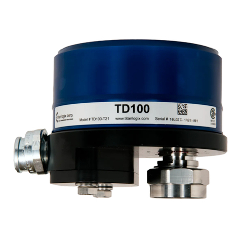
Titan Logix TD100 User manual

FINCH II – 6W Installation
Quick Reference Guide(v1.4)
www.titanlogix.com
Page 1
TD Series Transmitter
A Titan system must be installed and operated in accordance with the
details described in the Titan Logix manuals, application notes, and all
other relevant publications.
WARNING: Only qualified personnel familiar with the installation and
operation of this equipment should install, adjust, operate, or service this
equipment. Failure to observe these instructions could result in bodily
injury or loss of life.
INSTALLATION GUIDE
Step 1 Mount the FINCH II display, pg. 2
Step 2 Enable remote display, pg. 3
Step 3 Connect TD100 to FINCH II, pg. 3
Step 4 Connect to the vehicle power, pg. 4
Step 5 Connect to compartments 1 and 2, pg. 4
Step 6 Connect to compartments 3 and 4, pg. 5
Step 7 Connect to compartments 5 and 6, pg. 5
Step 8 Connect to Rack Control Module (RCM), pg. 6
Step 9 Complete the installation, pg. 6
FINCH II-6W Display
Dual Rod Probe
&
Cone
Coaxial Probe

FINCH II – 6W Installation
Quick Reference Guide(v1.4)
www.titanlogix.com
Page 2
INSTALLATION GUIDE
CHECKLIST
Ensure no flammable gases and/or fumes are present before installation or repair.
Turn the vehicle power off before any installation activity.
Ensure the tank is drained of liquid and free of vapors.
Observe all federal, state/provincial, and local safety standards and industry best practices.
Ensure all required tools are available for installation.
Secure all wires and cables with clips or cable ties and tighten all compression fittings.
Refer to the TD100 Installation & Operation Manual (TPM 057), FINCH II Installation & Operation Manual (TD010),
and the RCM installation manual (TPM 007) to view detailed procedures of any steps outlined in this Quick
Reference Guide.
Observe the following instructions during installation:
i. Wire splices should be made inside a weatherproof enclosure or junction box to prevent premature failure due
to corrosion.
ii. The TD100 transmitter terminal wiring area forms an explosion-proof enclosure. Care must be taken when
opening or closing the enclosure.
iii. To avoid damage due to water ingress the following care must be taken:
o Only 1 cable should be inserted per strain relief (gland)
o The cable’s outer diameter must be at least 0.260 inches (6.6mm)
o Tighten the strain relief until the cable is secure.
iv. Every FINCH II – 6W leaves the factory with 5 strain reliefs (glands) and 3 plugs.
o If the installation requires more than 5 glands, remove plugs to replace them with glands.
o If the installation requires less than 5 glands, replace all the unused glands with plugs before use.
Mount the FINCH II-6W Display
a. Attach the mounting tabs to the back of the FINCH display
b. Mount the display, ensuring that the unit is:
i. Installed in a location that does not exceed Class 1, Div.
2 hazardous area classification.
ii. Mounted in a protected area, shielded from wheel spray and stones.
iii. Not operated in temperatures less than -40C and greater than +65.
1

FINCH II – 6W Installation
Quick Reference Guide(v1.4)
www.titanlogix.com
Page 3
Enable Remote Display
a. To enable the display to stay ON while in use, access the FINCH II-
6W circuit board and connect DISPLAY EN and GND using a jumper
wire as shown.
Connect TD100 to FINCH II-6W
a. Use the Titan-supplied explosion-proof harness (wire kit) to connect
the TD100 cable to the FINCH II-6W.
b. Insert wires from the explosion-proof elbow into the 1/2” thread for the
connector and tighten the union nut on the TD100 (see top view).
c. Make the following connections:
i. TD100 Power (PWR) to FINCH II-6W Power (PWR) - Black Wire
ii. TD100 Ground (GND) to FINCH II-6W Ground (GND) - White
Wire
iii. TD100 SV (SV Bus) to FINCH II-6W SV (SV) - Red or Green Wire
2
3

FINCH II – 6W Installation
Quick Reference Guide(v1.4)
www.titanlogix.com
Page 4
Connect to the Vehicle Power
a. TRAILERS - connect the FINCH II power and ground to the nose box
or junction box electrical connector.
TANK TRUCKS - connect FINCH II system power to a switched
accessory power connection from the battery.
b. Pass the power cable from a vehicle through a strain relief (gland) and
connect it to power and ground as shown in the image.
c. Tighten the strain relief until the cable cannot be pulled, leaving
enough cable inside so the door can be opened.
Connect to Compartments 1 and 2
a. Install wire harness from TD100 on Compartment 1 through a gland
to COMP #1 following the colour sequence as shown in the picture.
b. Install wire harness from TD100 on Compartment 2 through a gland
to COMP #2 following the colour sequence as shown in the picture
4
Note
:
Some
wire
harnesses
have
GREEN
coloured wired instead of
RED
,
ensure the colour sequence matches what was connected to the TD100
terminal strip.
5

FINCH II – 6W Installation
Quick Reference Guide(v1.4)
www.titanlogix.com
Page 5
Connect to Compartments 3 and 4
a. Install wire harness from TD100 through a gland to the terminal
block for COMP #3 on the SV3/4 daughter card following the colour
sequence as shown in the picture.
b. Install wire harness from TD100 through a gland to the terminal
block for COMP #4 on the SV3/4 daughter card following the colour
sequence as shown in the picture.
Connect to Compartments 5 and 6
a. Install wire harness from TD100 through a gland to the terminal
block for COMP #5 on the SV5/6 daughter card following the
colour sequence as shown in the picture.
b. If your installation involves a Rack Control Module, then jump to
step 8. If you want to connect to the sixth compartment instead,
please follow through with the next step.
c. Install wire harness from TD100 through a gland to the terminal
block for COMP #6 on the SV5/6 daughter card following the
colour sequence as shown in the picture
Note
:
I
t may be easier to remove the connector from the daughter board to
install the wires as shown in the image.
6
7

FINCH II – 6W Installation
Quick Reference Guide(v1.4)
www.titanlogix.com
Page 6
Connect to the Rack Control Module
a. Install wire harness from Rack Control through a gland to the SV
out connector of the FINCH II
b. Connect Power and Ground (Black & White Wires) to the terminal
strip and connect the Red & Green to a 3-way connector as shown
in Figure 1 and Figure 2
c. Connect a 3rd wire (Yellow) to the 3-way connector and install it
into SV 6 of the expansion board. (Figure 3) Other wires connected
to SV 3/4 and SV 5 have been removed for clarity in Figure 4.
d. Make sure to wrap the 3-way connector with electrical tape to
insulate the metal part from the rest of the circuitry.
Complete the Installation
a. Replace the FINCH II circuit board cover and any other system
cover/ enclosure, ensuring all connections are secure before
applying power to the TD100 system.
b. Complete the programming of FINCH II following the steps
described in FINCH II Programming and Configuration Guide.
c. Visually confirm if the number of compartments displayed in the
Finch II matches the number of compartments in the truck.
d. In the event error messages are observed when applying power to
the system, refer to the Troubleshooting section of the TD100
Installation & Operation Manual (TPM 057).
9
8
Note
:
Currently,
t
he
FINCH
II Multi Compartment display
supports
connections
up to the total of 6 compartments or 5 compartments and RCM (Rack Control
Module).
Note
:
This image
is for a specific installation that involves 5 compartments
and an RCM. Your final product may look different based on your
installation configuration.
Figure 1
Figure 3 Figure 4
Figure 2
Other manuals for TD100
2
This manual suits for next models
2
Table of contents
Other Titan Logix Measuring Instrument manuals
Popular Measuring Instrument manuals by other brands
Novus
Novus NHDR-6004-H1-II user manual

Boonton
Boonton 92BD instruction manual

Blue-White industries
Blue-White industries F-2000 instruction manual

Endress+Hauser
Endress+Hauser Waterpilot FMX21 Additonal operating & safety instructions

KIMBALL MIDWEST
KIMBALL MIDWEST 84-1405 instruction manual

LI-COR
LI-COR LI-3000C instruction manual