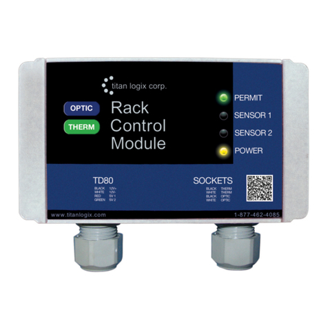
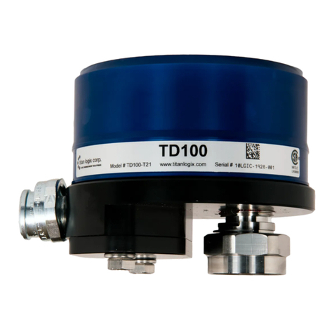
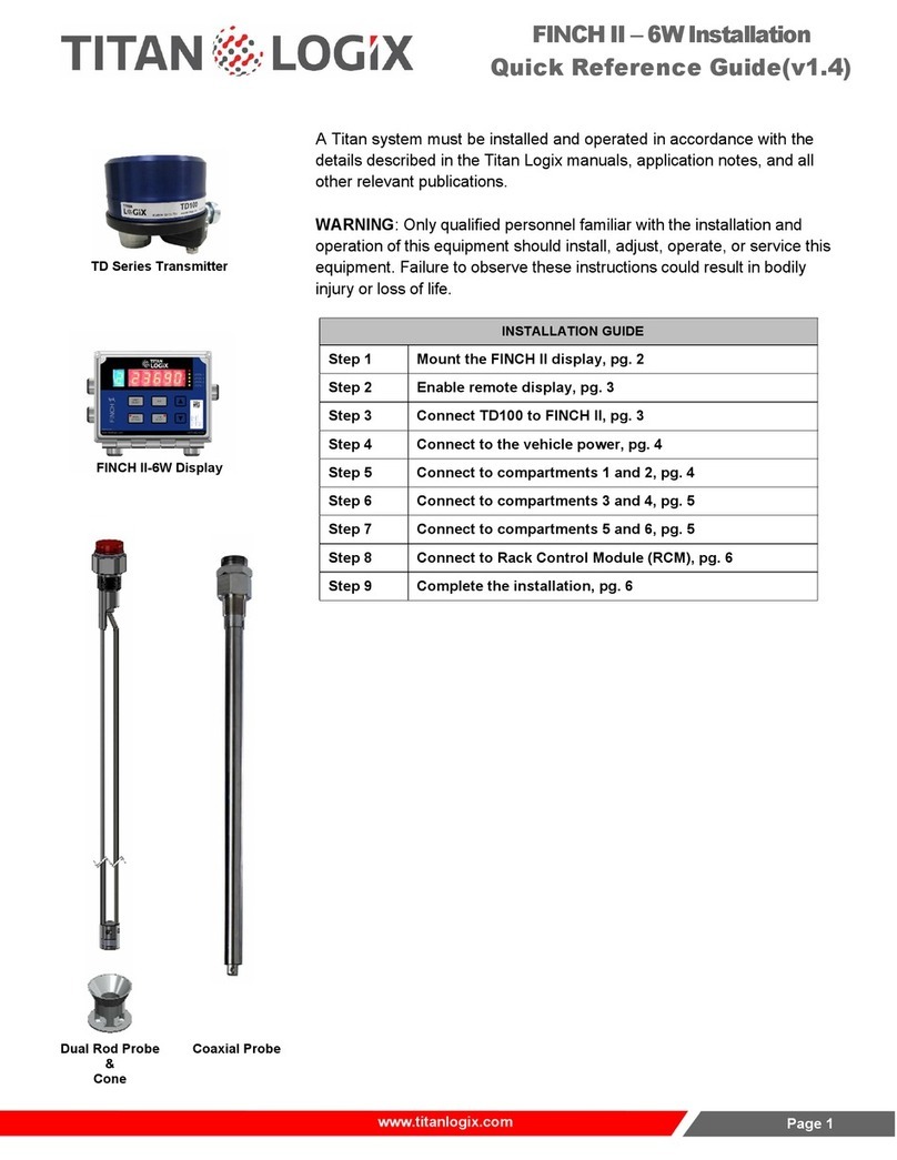
Titan Logix TD80 User manual

TD80™Level Gauging and Overfill Prevention System Product Manual
Rev. 2, August 4, 2015/ TD80 Introduction Page 1
TPM 001
WARRANTY
Please see our Terms and Conditions for details about our product warranty.
PROPRIETARY INFORMATION
The Information disclosed herein contains proprietary rights of Titan Logix Corp. Neither
this document nor the information disclosed herein shall be reproduced or transferred to
other documents, or used or disclosed to others for manufacturing purposes, or for any
other purpose except as specifically authorized in writing by Titan Logix Corp.

TD80™Level Gauging and Overfill Prevention System Product Manual
Page 2 TD80 Introduction/ Rev. 2, August 4, 2015
TPM 001
Table of Contents
1TD80 Introduction....................................................................................................................5
1.1 About This Manual..........................................................................................................5
1.2 Disclaimer.......................................................................................................................5
1.3 TD80 System Introduction and Description....................................................................6
1.3.1 About the TD80 System.........................................................................................6
1.3.2 TD80 System Components....................................................................................6
1.3.3 Optional Components ............................................................................................7
1.3.4 Theory of Operation...............................................................................................7
1.3.5 The TD80 Alarm System........................................................................................9
1.4 Overfill Prevention System Description ........................................................................11
1.5 Graphical Glossary of Terms........................................................................................14
2TD80 Installation....................................................................................................................17
2.1 TD80 Installation Steps Overview ................................................................................17
2.1.1 Pre-Installation Requirements..............................................................................17
2.1.2 Installation Steps Overview..................................................................................17
2.1.3 TD80 Installation Guidelines................................................................................19
2.2 TD80 Installation Test and Calibration .........................................................................19
2.2.1 TD80 Basic Operation Tests................................................................................19
2.2.2 TD80 System Testing and Verification.................................................................19
2.2.3 Offset Calibration Methods ..................................................................................21
2.3 TD80 Probe and Transmitter Location .........................................................................24
2.3.1 Locating the Probe...............................................................................................24
2.3.2 Locating the Transmitter......................................................................................25
2.3.3 Mounting the Top Fitting ......................................................................................26
2.3.4 Mounting the Anchor Cone ..................................................................................27
2.4 TD80 Mechanical Installation........................................................................................28
2.4.1 Overview of the Installation Procedure................................................................29
2.4.2 Installation Procedure ..........................................................................................29
2.5 TD80 Basic System Installation Wiring.........................................................................38
2.5.1 Finch 5332E/PS External Display, Red Terminal Board Wiring Instructions.......38
2.5.2 Finch 5332E External Display, Green Terminal Board Wiring Instructions .........38
2.5.3 Finch 5332, Internal Display Wiring Instructions..................................................39
2.6 TD80 Basic Alarm Installation Wiring ...........................................................................45
2.6.1 Finch 5332E/PS, Red Terminal Board Wiring Instructions..................................45
2.6.2 Finch 5332E, Green Terminal Board Wiring Instructions ....................................45
2.7 TD80 Overfill Prevention System Installation Wiring....................................................49
2.7.1 Finch Relay Module Installation Wiring................................................................49
2.7.2 P2000 Overfill Prevention System .......................................................................61
2.7.3 ABS Power Supply Wiring Example ....................................................................65
2.8 Finch Display Terminal and Jumper Locations.............................................................66
2.9 TD80 Installation Checklist...........................................................................................70
3TD80 and Overfill Prevention System Troubleshooting....................................................71
3.1 Overview and General Techniques ..............................................................................71
3.2 TD80 System Specific Troubleshooting .......................................................................72
3.2.1 Common System Wiring and Component Failures..............................................73
3.2.2 Common Installation Wiring and Component Problems......................................84
3.3 Alternate TD80 System Troubleshooting......................................................................88
3.4 TD80 System Tests ......................................................................................................88
4TD80 Technical Reference....................................................................................................98
4.1 Technical Specification Guide for Dual Rod Probes ....................................................98
4.2 Technical Specification Guide for Coaxial Probes......................................................106
5TD80 Operation....................................................................................................................114

TD80™Level Gauging and Overfill Prevention System Product Manual
Rev. 2, August 4, 2015/ TD80 Introduction Page 3
TPM 001
5.1 TD80 System Components.........................................................................................116
5.2 Introduction to Operation............................................................................................116
5.3 TD80 Operation ..........................................................................................................117
5.4 MODES OF OPERATION ..........................................................................................120
5.4.1 Alarm Disable Mode...........................................................................................120
5.4.2 Display Mode .....................................................................................................120
5.4.3 Monitor Mode .....................................................................................................120
5.4.4 Set Fill / Fall Mode .............................................................................................121
5.5 ALARMS.....................................................................................................................121
5.5.1 Spill Alarm..........................................................................................................121
5.5.2 Fill / Fall Alarm ...................................................................................................122
5.5.3 High High Alarm.................................................................................................122
5.5.4 Fail Alarm...........................................................................................................122
5.5.5 Disabling the 2 LO Message..............................................................................122
5.6 Alarms Settings...........................................................................................................123
5.6.1 Fill/Fall Alarm .....................................................................................................123
5.6.2 HH Alarm............................................................................................................123
5.6.3 Spill/Fail Alarm...................................................................................................123
5.7 Offset Calibration........................................................................................................124
5.8 Normal Operation Troubleshooting ............................................................................125
6TD80 Programming .............................................................................................................127
6.1 TD80 Transmitter and Probe Description...................................................................127
6.2 Programming the TD80 ..............................................................................................127
6.3 Birdfeeder 2 Programming Steps ...............................................................................128
6.3.1 Introduction ........................................................................................................128
6.3.2 Programming Procedure....................................................................................128
6.3.3 TD80 Birdfeeder 2 Detailed Programming Instructions.....................................131
6.3.4 Graphical TD80 Programming Instructions using Birdfeeder 2 .........................133
6.3.5 Connecting the TD80 for Programming Using the SVRS232 to USB Converter
...........................................................................................................................146
6.3.6 Advanced Birdfeeder 2 Programming Operations.............................................152
6.3.7 MDU (Birdfeeder) Programming........................................................................160
6.3.8 Programming Checklist......................................................................................162
Index of Figures
Figure 1-1: Dual Rod Probe Truck & Trailer Installation................................................................14
Figure 1-2: Coaxial Probe Truck & Trailer Installation...................................................................15
Figure 1-3: SV Programming Kit....................................................................................................16
Figure 2-1: Sample Depth Chart....................................................................................................23
Figure 2-2: Locating the Probe ......................................................................................................24
Figure 2-3: Trailer Mounted Tank ..................................................................................................25
Figure 2-4: Locating the Top Fitting...............................................................................................26
Figure 2-5: Locating the Anchor Cone...........................................................................................27
Figure 2-6: Mechanical Installation of the TD80 System ...............................................................28
Figure 2-7: Dual Rod Probe Measurement....................................................................................33
Figure 2-8: Cutting the Dual Rod Probe.........................................................................................34
Figure 2-9: Correct Probe Installation............................................................................................35
Figure 2-10: Coaxial Probe Measurement.....................................................................................36
Figure 2-11: Cutting the Coaxial Probe..........................................................................................37
Figure 2-12: Basic System Wiring Diagram for Finch 5332E/PS External Display .......................40
Figure 2-13: Basic System Wiring Schematic for Finch 5332E/PS External Display ....................41
Figure 2-14: Basic System Wiring Diagram for Finch 5332E External Display.............................42
Figure 2-15: Basic System Wiring Schematic for Finch 5332E External Display..........................43
Figure 2-16: Basic System Wiring Diagram for Finch 5332 Internal Display.................................44
Figure 2-17: Basic Alarm Wiring Diagram for Finch 5332E/PS External Display..........................47
Figure 2-18: Basic Alarm Wiring Diagram for Finch 5332E External Display................................48

TD80™Level Gauging and Overfill Prevention System Product Manual
Page 4 TD80 Introduction/ Rev. 2, August 4, 2015
TPM 001
Figure 2-19: Overfill Prevention Installation Example....................................................................49
Figure 2-20: Finch Relay Module Internal Wiring Diagram............................................................52
Figure 2-21: Finch Relay Module Overfill Prevention System Wiring Diagram for Finch 5332E/PS
with Horns and Lights............................................................................................................53
Figure 2-22: Finch Relay Module Overfill Prevention System Wiring Schematic for Finch
5332E/PS with Horns and Lights...........................................................................................54
Figure 2-23: Finch Relay Module Overfill Prevention System Wiring Diagram for Finch 5332E with
Horns and Lights ...................................................................................................................55
Figure 2-24: Finch Relay Module Overfill Prevention System Wiring Schematic for Finch 5332E
with Horns and Lights............................................................................................................56
Figure 2-25: Basic Shutdown Wiring Diagram for Finch 5332E/PS External Display ...................57
Figure 2-26: Basic Shutdown Wiring Schematic for Finch 5332E/PS External Display................58
Figure 2-27: Basic Shutdown Wiring Diagram for Finch 5332E External Display.........................59
Figure 2-28: Basic Shutdown Wiring Schematic for Finch 5332E External...................................60
Figure 2-29: Single P2000 Overfill Prevention System Wiring Diagram........................................61
Figure 2-30: Single P2000 Overfill Prevention System Wiring Schematic ....................................62
Figure 2-31: Dual P2000 Overfill Prevention System Wiring Diagram ..........................................63
Figure 2-32: Dual P2000 Overfill Prevention System Wiring Schematic.......................................64
Figure 2-33: ABS Power Supply Wiring Example Schematic........................................................65
Figure 2-34: Finch 5332E External Display Terminal Board..........................................................66
Figure 2-35: Finch 5332E/PS External Display Terminal Board....................................................67
Figure 2-36: Finch 5332 Internal Display Jumper Settings............................................................68
Figure 2-37: Finch 5332E(/PS) External Display Jumper Settings................................................69
Figure 3-1: Basic System Wiring Schematic for Finch 5332E/PS External Display......................90
Figure 3-2: Basic System Wiring Schematic for Finch 5332E External Display............................91
Figure 3-3: Basic System Wiring Diagram for Finch 5332 Internal Display...................................92
Figure 3-4: Single P2000 Overfill Prevention System Wiring Schematic ......................................93
Figure 3-5: Finch Relay Module Overfill Prevention System Wiring Schematic for Finch 5332E
with Horns and Lights............................................................................................................94
Figure 3-6: Basic Shutdown Wiring for Finch 5332E/PS External Display....................................95
Figure 3-7: Finch Relay Module Overfill Prevention System for Finch 5332E/PS with Horns and
Lights.....................................................................................................................................96
Figure 3-8: Basic Shutdown Wiring Schematic for Finch 5332E External Display........................97
Figure 5-1: Dual Rod Probe Truck & Trailer Installation..............................................................114
Figure 5-2: Coaxial Probe Truck & Trailer Installation.................................................................115
Figure 5-3: Coaxial Probe Alarm Settings....................................................................................123
Figure 5-4: Dual Rob Probe Alarm Settings.................................................................................123
Figure 6-1: Connecting the TD80 for Programming in the Shop .................................................146
Figure 6-2: Connecting the TD80 for Programming in the Shop Drawing...................................147
Figure 6-3: Connecting the TD80 for Programming on a vehicle with a Finch 5332E Display
(green board).......................................................................................................................148
Figure 6-4: Connecting the TD80 for Programming on a vehicle with a Finch 5332E Display
(green board) Drawing ........................................................................................................149
Figure 6-5: Connecting the TD80 for Programming on a vehicle with a Finch 5332E/PS Display
(red board)...........................................................................................................................150
Figure 6-6: Connecting the TD80 for Programming on a vehicle with a Finch 5332E/PS Display
(red board) Drawing.............................................................................................................151
Figure 6-7: MDU Text file sample ................................................................................................153
Figure 6-8: Blank Depth Chart Form............................................................................................159
Index of Tables
Table 1-1: Sequence of Events with Finch Relay Module installed...............................................13
Table 2-1: TD80 Installation Checklist ...........................................................................................70
Table 5-1: Normal Operation Troubleshooting.............................................................................126
Table 6-1: Programming Checklist...............................................................................................162

TD80™Level Gauging and Overfill Prevention System Product Manual
Rev. 2, August 4, 2015/ TD80 Introduction Page 5
TPM 001
1 TD80 Introduction
1.1 About This Manual
This instruction manual provides information specific to the Titan Logix Corp. TD80™
(hereafter referred to as the TD80) Level Gauging and Overfill Prevention System. Other
peripheral equipment should be supplied with its own instruction manual and that manual
should be referred to for proper operation of the peripheral equipment.
It is essential that this manual be read and understood for proper installation and
operation of your new TD80™Level Gauging and Overfill Prevention System.
THIS MANUAL INCLUDES:
Introduction Description of the key features and components of the
TD80 Level Gauging and Overfill Prevention System.
Installation Description of mounting and wiring of equipment.
Troubleshooting Description of possible problems, their probable causes,
and solutions.
Technical Reference Technical Specification Guides.
Operation Description of Operation and Alarms.
Programming Description of Programming requirements and steps.
1.2 Disclaimer
The information in this document is subject to change without notice. Titan Logix Corp.
makes no representations or warranties with respect to the contents hereof.
Only qualified personnel should install this product. Please read this manual before
installing this product and follow all applicable safety and electrical regulations as
required.

TD80™Level Gauging and Overfill Prevention System Product Manual
Page 6 TD80 Introduction/ Rev. 2, August 4, 2015
TPM 001
1.3 TD80 System Introduction and Description
1.3.1 About the TD80 System
The TD80 Level Transmitter is the heart of the TD80 level measurement
system. The TD80 transmitter uses Guided Wave RADAR (GWR) to
measure liquid level in a tank. It does not use any moving parts for level
measurement.
Guided Wave RADAR is a contacting level measurement method that uses a
probe as a wave guide to channel the radio frequency energy to the liquid
being measured. The probe provides an efficient path for the transmitted
energy and pulse reflections from the surface of the liquid.
The TD80 transmitter measures the time delay between transmitted and
reflected pulses to calculate distance to the material’s surface. This distance
is then used to determine level of the liquid in the tank.
The calculated level is converted into common volume units and is sent to a
Display such as the Finch 5332 Display. The display is also part of an
optional secondary overfill prevention system. TD80 generated alarms
provide the approaching overfill information to halt loading at industry
standard optic controlled loading racks, on-board loading pumps or valves.
The TD80 system consists of a TD80 transmitter, dual rod or coaxial probe
and a Finch Display. Optional components such as the Finch Relay Module,
horns and lights are installed as required.
1.3.2 TD80 System Components
TD80 Transmitter
The TD80 transmitter generates and processes the GWR signals to
determine liquid level in a tank. The TD80 is mounted on the tank top and
connected to the probe, is weatherproof and rated for use in hazardous
locations where explosive fumes may be present. TD80s are available in two
versions, dual rod or coaxial probe for compatibility with a wide range of
liquids.
Probe
The probe guides the transmitted pulse and reflection from the surface of the
liquid. Probes are available in dual rod or coaxial versions and require a
matching transmitter type. The probe is mounted on the tank top and is
connected to the bottom of the transmitter. Dual rod probes are designed for
viscous liquids. Coaxial probes are used mostly for tanks containing products
like aviation fuel.
Finch 5332 Display
Finch Displays are available in weather-proof external versions, the Finch
5332E and a smaller internal version, the Finch 5332. Both provide bright
LED numeric display of volume information, alarms and system error codes
from the TD80 transmitter. Various alarm and error conditions are detected
by the transmitter and display. These alarm states control three internal
relays for alarm annunciation, overfill and low level prevention.

TD80™Level Gauging and Overfill Prevention System Product Manual
Rev. 2, August 4, 2015/ TD80 Introduction Page 7
TPM 001
1.3.3 Optional Components
P2000
The P2000 is an accessory that enables secondary overfill prevention when
used with industry standard optic loading rack controllers.
MIC 10
The MIC 10 is an interface device for connecting multiple TD80s to a third
party modem.
Finch Relay Module
The Finch Relay Module is an accessory that enables overfill prevention by
control of an onboard pump or loading valve.
Horns and Lights
Alarm reporting is through optional vehicle mounted horns and lights.
1.3.4 Theory of Operation
Overview
The TD80 system consists of a TD80 transmitter, dual rod or coaxial probe
and an internal or external Finch Display. Optional components such as
horns and lights are installed as required.
The TD80 continuously measures liquid level in the tank and transmits
volume information with alarm states to the Finch Display. This information is
presented on a large 4 digit display and to alarm controlled relays. Alarms
and errors control three separate relays to signal or control external devices.
These relays indicate Spill, High-High (HH) and system Fail alarms to
external devices such as overfill prevention valves, lights, horns and
stationary loading controls.
The HH, Spill and system Fail alarms provide information to the P2000 or
Finch Relay Module and only permits loading while all conditions are safe.
HH is normally the first shutdown level; Spill is a backup level slightly higher
than HH, while Fail indicates failure of the TD80 system. Activation of any
alarm halts loading to prevent a dangerous overfill condition or spill at the
loading rack.
TD80 Transmitter and Probe
The TD80 transmits a continuous stream of radio frequency pulses into the
probe. These pulses travel along the probe and part of the pulse energy is
reflected back to the transmitter when encountering the surface of the liquid
in a tank.
Time delay between the transmit pulse and reflected pulse is used to
calculate the distance from the tank top mounted transmitter to the liquid
level.

TD80™Level Gauging and Overfill Prevention System Product Manual
Page 8 TD80 Introduction/ Rev. 2, August 4, 2015
TPM 001
The TD80 contains a table describing the tank depth and volumetric
characteristics. This table is programmed before installation and operation on
the tank. Liquid level is calculated from the table using maximum depth of the
tank and distance from the top to the liquid surface. The TD80 “sees” the
depth of air space in the tank and calculates the loaded volume.
Physical limitations of GWR create a dead band at the bottom of the probe
where the transmitted pulse interferes with the reflected echo. This region of
dead band is considered to be the bottom 5.5” of the tank. Any liquid level
measured at 5.5” or less is indicated by the Finch as “2 LO”, meaning “too
low”. An upper dead band exists at 7.5” from the top on the dual rod and 2.5”
on the coaxial probe. Level measurements within the dead bands are
inaccurate and unreliable.
Calculated volume is transmitted to a Finch Display by SV Bus while a
linearly scaled level is sent by the optional 4-20mA interface. The Finch is
able to display up to 4 numeric digits, including a decimal point. This numeric
display correctly indicates volume of loaded product in the tank. The 4-20mA
output is scaled linearly for a volume of 0% at an output of 4mA and 100%
volume at 20mA.
SV Bus
SV Bus is a single wire serial digital communication interface with an error
checking protocol that eliminates false communication between the TD80
transmitter and Finch Display. SV Bus is one of the three wires required for
TD80 operation with the Finch. The other two wires are power and ground.
This bus is designed for reliable communications in stationary and transport
environments.
Finch Display
The Finch Display receives a continuous stream of volume information and
alarm states from the TD80 on the SV Bus. Volume, alarm states and errors
are shown on the 4 digit numeric display. An additional alarm is controlled
directly by the Finch. Alarms and errors control three separate relays to
signal or operate external devices.
TD80 controlled relays indicate Spill, High-High and system Fail alarms to
external devices such as overfill prevention valves, lights, horns and
stationary loading controls. The Finch controlled alarm and relay indicates a
preset, increasing Fill or decreasing Fall level to warn of an approaching
operator action while loading or unloading product.
The Fill/Fall and High-High Alarms remain active until acknowledged by the
operator. The Spill alarm remains active until the spill condition is cleared by
unloading product below the spill alarm level while the system is powered
and monitoring the changing level.
Alarms are acknowledged by button presses on the Finch or a push button
connected to the Alarm Acknowledge input.
TD80 reported errors or malfunctions are indicated by the Finch showing
“E xx”, where xx is an error code and activating the Fail alarm.
Finch reported loss of communication with the TD80 is indicated by showing
“----”and activating the Fail alarm.

TD80™Level Gauging and Overfill Prevention System Product Manual
Rev. 2, August 4, 2015/ TD80 Introduction Page 9
TPM 001
Relay Module
A Finch Relay Module is available to combine the Finch Spill/Fail and High-
High alarm relays with a signal from the vehicle mounted Power Take-Off
(PTO) to safely control an onboard overfill prevention system. The Relay
Module contains high current relays to energize a bottom loading valve or
hydraulic motor bypass valve for loading control. It also contains a terminal
strip for power and alarm accessory interconnections.
P2000
The P2000 is an accessory that enables secondary overfill prevention when
used with industry standard optic loading rack controllers. The Finch
controlled alarms provide an intrinsically safe signal to the P2000 that
permits or denies loading at the rack. The loading rack connections are
made through a standard 7-pin or 10-pin optic socket.
MIC 10
The MIC 10 is an interface device for connecting multiple TD80s to a third
party modem. Level, alarm and error information from the TD80s is collected
by the MIC 10 and forwarded to the modem. The modem is then able to
wirelessly transmit data to the back office for asset management and
tracking purposes.
It can be set to automatically transmit TD80 data at intervals based on a user
preferred configuration, or else can send data on command from the modem.
The MIC 10 features a PTO signal input to enable data transmission only
when the PTO is engaged. This limits the data bandwidth required by a
wireless modem.
1.3.5 The TD80 Alarm System
This description refers to TD80 transmitters and Finch 5332E/PS Display
(Red Terminal Board version). See notes in parentheses for the Finch 5332E
Display (Green Terminal Board version). Internal Finch 5332 description is
the same as the 5332E version. Internal Displays are connected by a pigtail
with labeled wires instead of a terminal board as in the external Finch
versions.
The TD80 alarms are listed below. A vehicle mounted Power Take Off (PTO)
unit may signal a loading or unloading event when alarms are required to be
activated. A Display Enable (PTO) (or Gauge Enable (PTO) on 5332E
Displays) signal to the Finch Display enables these alarms. An inactive PTO
signal holds all alarms in the non-alarming state to prevent false triggering
due to sloshing while driving. This PTO signal is usually a dry contact switch
closed by the mechanical engagement of the PTO.

TD80™Level Gauging and Overfill Prevention System Product Manual
Page 10 TD80 Introduction/ Rev. 2, August 4, 2015
TPM 001
Fill/Fall Alarm
Fill and Fall alarms share one relay output. The alarm is configured as a Fill
or a Fall alarm with Finch Display jumper J9. The alarm point is settable by
the operator. The Fill alarm is typically used to warn the operator when the
loading process is nearing maximum capacity. The Fall alarm is usually used
when unloading and a minimum volume of product must be retained in the
tank to prevent pump damage. Fill or Fall operation is determined when the
system is installed and is configured inside the Finch Display.
The Finch Display is the source of this alarm. Fill/Fall alarms are indicated by
the flashing the current level on the display and activating the Fill/Fall alarm
relay.
High-High (HH) Alarm
The High-High alarm is set during transmitter programming and is normally
the maximum safe volume of the tank. Dual Rod TD80 transmitters and
probes are settable to a volume from 8” below the tank top and lower while
the Coaxial TD80 transmitters and probes are able to be set from 3” and
lower.
The TD80 transmitter is the source of this alarm. The HH alarm is activated
by a measured volume equal to or exceeding the alarm level set during
programming. High-High alarms are indicated by alternately flashing “HH”
along with the current level on the Display and activating the HH alarm relay.
Spill Alarm
Spill is an approaching overfill condition. Dual Rod TD80 transmitters and
probes are factory set at 7.5” below the tank top while Coaxial TD80
transmitters and probes are selectable in the range of 2.5” down to 15.5”
from the top.
The TD80 transmitter is the source of this alarm. Spill alarms are indicated
by showing “SPill” on the display and activating the spill alarm through the
Spill/Fail (or Fail on the 5332E Displays) relay.
Fail Alarm
System failures such as internal transmitter errors, probe faults or loss of
communications are reported by the Spill/Fail (or Fail on the 5332E Displays)
relay.
The Finch Display reports communication failure. The TD80 transmitter is the
source for all other system errors. Errors are displayed as “E xx”, where xx is
an error code. Loss of communication between the TD80 and Finch is
displayed as “----“.
Alarm Relays
1. Fill/Fall relay
2. High-High relay
3. Spill/Fail (or Fail on 5332E Displays) relay.

TD80™Level Gauging and Overfill Prevention System Product Manual
Rev. 2, August 4, 2015/ TD80 Introduction Page 11
TPM 001
Devices such as horns and lights are connected to these alarm relays for
operator action. The Fall, High-High and Spill/Fail relays typically operate
shutdown controls including external relays, and solenoid operated valves.
1.4 Overfill Prevention System Description
The description below incorporates the recommended Finch Relay Module.
See the Overfill Prevention System Installation Section 2.7 for detail.
1. Power On
The TD80 and Finch proceed through the normal start-up sequence as
described below. Once completed; “OFF” will be displayed on the Finch.
Level is displayed for 30 seconds by a momentary press of the Up or Down
buttons.
2. PTO Engaged
The operator engages the truck mounted PTO to begin loading. The PTO
signal to the Finch is controlled by an air/electric switch that causes the
following to occur:
1. Finch Display to an active mode with all alarms enabled and continuous
level display.
2. A Solenoid is energized to allow loading by controlling a Normally
Closed bottom loading valve or a Normally Open hydraulic motor
bypass valve.
3. The Green Light is on to indicate loading is permitted.
4. The Red Light and Horn are off at the start of the loading process.
Bottom Loading Valves:
The unpowered condition of a bottom loading valve is normally closed. The
solenoid must be powered to allow loading. Any alarm condition for system
errors, failures or overfill will cause the solenoid to be de-energized and halt
the loading process. A disengaged PTO will also close the valve.
Hydraulic Bypass Valves.
The unpowered condition for a hydraulic motor bypass valve is normally
open. The solenoid must be powered to allow loading by closing the bypass
circuit. Any alarm condition for system errors, failures or overfill will cause the
solenoid to de-energize and halt the loading process. A disengaged PTO will
also open the valve.
3. Operator fills the tank
The liquid is loaded into the tank using either the on-board or a stationary
pump. When the liquid reaches the Fill alarm level, the following occurs:
a. The Red light and Horn turn on to alert the operator that he is getting
close to the loading limit and has to prepare to turn off the pump and
close the valve.
b. The Green Light stays on to indicate continued loading is permitted.

TD80™Level Gauging and Overfill Prevention System Product Manual
Page 12 TD80 Introduction/ Rev. 2, August 4, 2015
TPM 001
c. The Solenoid continues to be energized to allow loading.
d. The Finch Display flashes the level indication to indicate the active Fill
alarm.
The operator then presses either the Up or Down button on the Finch to
silence the horn, turn off the Red light and return to a normal level display.
The operator continues to load. He will likely manually shut off the pump and
close the valve before the liquid level reaches the HH alarm level. If he does
not and the liquid level reaches the HH alarm level, then the following occurs:
a. Green light turns off
b. The solenoid de-energizes, closing the bottom loading valve or opening
the on-board pump bypass valve. This halts the loading process.
If the tank has been loaded to the required amount, then the operator turns
off the pump, closes the valve, disconnects the hoses and drives away.
If the tank has not been loaded to the required amount, then the operator
clears the HH alarm on the Finch with the UP/UP/DOWN/UP button
sequence. This resets the alarm response and allows further loading with the
following:
a. The Green Light turns back on
b. The Solenoid is re-energized
c. The Solenoid either opens the bottom loading valve or closes the on-
board pump bypass valve to allow loading to continue.
The operator is likely to stop loading before the level reaches the Spill alarm
level.
If the operator continues to load and reaches the Spill alarm level, the
following occurs:
a. Green Light turns off
b. The Solenoid is de-energized
c. The de-energized solenoid either closes the bottom loading valve or
opens the on-board pump bypass valve to halt the loading process.
The operator cannot reset or acknowledge the Spill alarm. The liquid must be
pumped out of the tank until it drops several inches below the HH alarm
level. The Spill alarm then clears and enables loading through a bottom
4. PTO Disengaged
When the operator has completed the loading procedure, he turns off the
PTO. This deactivates the Finch alarms, displays “OFF” and prevents the
solenoid from energizing to disable loading through a bottom loading valve or
a bypass valve on a hydraulic motor.
He now drives to a new location to load or unload.

TD80™Level Gauging and Overfill Prevention System Product Manual
Rev. 2, August 4, 2015/ TD80 Introduction Page 13
TPM 001
5. Sequence of Events with Finch Relay Module installed
Table 1-1: Sequence of Events with Finch Relay Module installed
Event Sequence
Finch
Display
Red Light,
Horn
Green Light
Solenoid
Truck started, PTO NOT
engaged
“OFF”
Pulsed, then
OFF
OFF
OFF
PTO engaged
2 LO or
Level
OFF
ON
ON
Liquid loaded to Fill level
Flashing
Level
ON
ON
ON
Operator presses UP or DOWN
button
Level
OFF
ON
ON
Liquid loaded to HH alarm level
“HH”/Level
OFF
OFF
OFF
Operator presses
UP/UP/DOWN/UP
Level
OFF
ON
ON
Liquid loaded to Spill level
“SPILL”
OFF
OFF
OFF
PTO is disengaged. Operator
drives to next site.
“OFF”
OFF
OFF
OFF
Operator pumps out liquid with
PTO engaged.
Level
OFF
ON
ON
All liquid is pumped out
2 LO
OFF
ON
ON
PTO is disengaged. Operator
drives to next site
“OFF”
OFF
OFF
OFF

TD80™Level Gauging and Overfill Prevention System Product Manual
Page 14 TD80 Introduction/ Rev. 2, August 4, 2015
TPM 001
1.5 Graphical Glossary of Terms
Dual Rod Probe Truck and Trailer Installation
Figure 1-1: Dual Rod Probe Truck & Trailer Installation

TD80™Level Gauging and Overfill Prevention System Product Manual
Rev. 2, August 4, 2015/ TD80 Introduction Page 15
TPM 001
Coaxial Probe Truck and Trailer Installation
Figure 1-2: Coaxial Probe Truck & Trailer Installation

TD80™Level Gauging and Overfill Prevention System Product Manual
Page 16 TD80 Introduction/ Rev. 2, August 4, 2015
TPM 001
TD80 Programming
SV PROGRAMMING KIT
Figure 1-3: SV Programming Kit
PC PROGRAMMING SOFTWARE,BIRDFEEDER 2
Figure 1-4: PC Programming Software Birdfeeder 2

TD80™Level Gauging and Overfill Prevention System Product Manual
Rev. 2, August 4, 2015/ TD80 Installation Page 17
TPM 001
2 TD80 Installation
2.1 TD80 Installation Steps Overview
2.1.1 Pre-Installation Requirements
1. When choosing a location to install the TD80 components, the following guidelines
must be followed:
a. Appropriate industry, national, provincial/state and local codes
b. Fuses and components appropriate for the area classification
2. The tank is completely drained of liquid and vapour free
3. No drilling or welding to the tank and frame without first consulting with the tank
manufacturer.
4. Refer to the TD80 installation guidelines 2.1.3 for the following:
a. Probe and Transmitter location
i. Dual Rod
ii. Coaxial
b. Finch Display location
c. Finch Relay Module location
d. Electrical requirements
2.1.2 Installation Steps Overview
1. Program the TD80
a. The TD80 must be programmed before use. Programming may be done at the
factory when purchased, by the customer prior to installation or after installation
on the vehicle when necessary.
b. See the Programming Instructions 6.3 for detail.
2. Install the 1” NPT Top Fitting (collar)
a. Ensure that the top fitting position allows the probe to fit vertically into the tank.
b. Weld the top fitting to the tank top
c. See the Mechanical Installation Instructions 2.4 for detail.
3. Install the Anchor Cone
a. Ensure that the anchor cone is directly under the collar, within 3 degrees from
vertical.
b. Weld the anchor cone to the tank bottom
c. See the Mechanical Installation Instructions 2.4 for detail.
4. Install the Probe
a. Cut probe to length
b. Install with Teflon tape or anti-seize compound
c. The probe must fit into the anchor cone without bending, twisting or binding.
d. See the Mechanical Installation Instructions 2.4 for detail.
5. Mount the Transmitter
a. Do not use Teflon tape or anti-seize compound
b. Hand-tighten the transmitter nut, and then use a wrench to secure the
connection.
c. See the Mechanical Installation Instructions 2.4 for detail.
6. Mount the Finch Display
a. See the Mechanical Installation Instructions 2.4 for detail.

TD80™Level Gauging and Overfill Prevention System Product Manual
Page 18 TD80 Installation/ Rev. 2, August 4, 2015
TPM 001
7. Mount the Relay Module (optional)
a. See the Mechanical Installation Instructions 2.4 for detail.
8. Mount the Alarm Accessories (optional)
a. Lights
b. Horns
c. Alarm Acknowledge push button
d. See the Mechanical Installation Instructions 2.4 for detail.
9. Inspect the Mechanical Installation
a. See the Mechanical Installation Instructions 2.4 for detail.
10. Install the Electrical Wiring
a. The TD80 transmitter is provided with a 50’ or 75’ cable kit. It is recommended to
use the kit with included sealing fitting for connection to the Finch Display.
b. All electrical grounding is to the vehicle or trailer electrical ground connection and
not to the chassis.
c. For trailers, connect the TD80 system power and ground to the nose box
electrical connector. For trucks, connect TD80 system power to a switched
accessory power connection from the battery.
d. Wire splices should be made inside a weather proof enclosure or junction box to
prevent premature failure due to corrosion.
e. Secure all wires and cabling with clips or cable ties
f. Tighten all compression fittings
g. Refer to the specific installation wiring diagrams and instructions for details. See
sections 2.5, 2.6, 2.7 for wiring examples.
11. Set and Verify the Finch Display Jumpers. Place the following jumpers in the
positions required for the installation. See Figure 2-36 & Figure 2-37.
a. Decimal point, J2 to J5
b. Fill alarm relay, J1
c. Fail/Spill relay, J10
d. Fill/Fall alarm, J9
12. Confirm Finch 5332E/PS (red terminal board) Fuses are Installed with Correct Type
(Ceramic, Sand Filled, 5x20mm) and Rating (F1, F3-F5: 2A, F2: 5A) or Finch 5332E
(green terminal board) 3A Blade Fuse is installed in a non-hazardous location. See
Figure 2-35.
13. Perform the TD80 Basic Operation Test
a. See section 2.2.1.
14. Verify the TD80 Programming Information
a. Correct depth chart and units
b. Fill or Fall alarm level
c. HH level
d. Spill Level
15. Set the Fill or Fall Alarm Level Volume
16. Perform TD80 System Test and Verification
a. See section 2.2.2
17. Perform the Offset Calibration
a. See section 2.2.3

TD80™Level Gauging and Overfill Prevention System Product Manual
Rev. 2, August 4, 2015/ TD80 Installation Page 19
TPM 001
2.1.3 TD80 Installation Guidelines
Probe and Transmitter Location: See TD80 Probe and Transmitter Location 2.3 for
details.
Finch Display Location:
a. Locate Finch 5332, internal Display
i. Sheltered from weather and moisture
ii. Easily visible and within reach of the operator
iii. Must be located in a non-hazardous area
b. Locate Finch 5332E external Display
i. Shielded from wheel spray and stones
ii. Easily visible and within reach of the operator
c. Avoid the following locations:
i. Direct sunlight
ii. Temperatures less than -40C and greater than +65C
iii. Near high voltage/current wiring, contactors, inverters and radio transmitters.
Finch Relay Module Location:
a. Must be located in a non-hazardous area.
Electrical Requirements: See the TD80 Dual Rod or Coaxial Technical Specifications for
details.
2.2 TD80 Installation Test and Calibration
2.2.1 TD80 Basic Operation Tests
The following steps describe basic tests to confirm that the TD80 system is functional
after installation or repair. Troubleshoot and repair all problems if the test results differ
from the ones shown.
1. Inspect installation before power is applied.
2. Turn power on to the TD80 system. The Display should turn on and go through its
start-up sequence (approximately 10 seconds long).
a. Display is tested, showing numbers 0 thru 9 and then letters A thru F
3. Display will show “----”for up to several seconds, then one of the following:
a. “2 LO” if the tank is empty or contains liquid and the depth is less than 5.5”
b. Level if the tank contains liquid and the depth is greater than 5.5”
c. Error message “E xx”, where xx is a number
d. “SPill”
2.2.2 TD80 System Testing and Verification
The following steps describe tests and to be completed after mechanical and electrical
installation of the TD80 system. These tests may also be used to confirm correct system
operation after repair. Normal responses are indicated for each test. Proceed to
troubleshooting if the test results differ from the ones shown.
1. Turn power on to the TD80 system. The Display should turn on and go through its
start-up sequence (approximately 10 seconds long).
a. Display is tested, showing numbers 0 thru 9 and then letters A thru F
b. Fill/Fall alarm is pulsed

TD80™Level Gauging and Overfill Prevention System Product Manual
Page 20 TD80 Installation/ Rev. 2, August 4, 2015
TPM 001
i. Installed light will blink
ii. Installed horn will briefly sound
iii. Installed underfill prevention system will activate then deactivate
c. Fail/Spill alarm is pulsed
i. Installed light will blink
ii. Installed horn will briefly sound
iii. Installed Overfill prevention system will activate then deactivate
2. Display will show “----”for up to several seconds, then one of the following:
a. “2 LO” if the tank is empty or contains liquid and the depth is less than 5.5”
b. Level if the tank contains liquid and the depth is greater than 5.5”
c. Error message “E xx”, where xx is a number
d. “SPill”
3. Test the volume display by doing the following:
a. For dual rod probes, run your hand along the probe to check the volume display
and alarm settings. If the probe is not within reach, use foil or a metal rod to short
the two probe rods together.
i. Volume displayed will increase as the hand or shorting rod moves toward the
top of the compartment
ii. Volume displayed will decrease as the hand or shorting rod moves toward
the bottom of the compartment
b. For coaxial probes, insert a small metal rod into the holes along the probe. Short
the center rod to the outer tube to check the volume and alarm settings.
i. Volume displayed will increase as the shorting rod moves toward the top of
the compartment
ii. Volume displayed will decrease as the shorting rod moves toward the bottom
of the compartment
4. Set the Fill alarm according to the customer’s requirements.
5. Clear all active alarms.
6. Confirm that the following occurs when the probe is shorted at selected points:
a. “2 LO” is displayed when the tank level is less than 5.5”. Volume is displayed
when the level is above 5.5”.
b. Installed Fall alarm activates when the tank level decreases to or is less than the
Fall alarm setting.
i. Display flashes the volume
ii. Installed light and horn activate
iii. Installed underfill prevention system activates
c. Installed Fall alarm deactivates when either the Up or Down button is pressed.
i. Display returns to normal, not flashing
ii. Installed light and horn deactivate
iii. Installed underfill prevention system deactivates
d. Installed Fill alarm activates when the tank level increases to or exceeds the Fill
alarm setting.
i. Display flashes the volume
ii. Installed light and horn activate
e. Installed Fill alarm deactivates when either the Up or Down button is pressed.
i. Display returns to normal, not flashing
ii. Installed light and horn deactivate
f. HH alarm activates when the tank level reaches the HH alarm setting.
Other manuals for TD80
1
Table of contents
Other Titan Logix Measuring Instrument manuals
Popular Measuring Instrument manuals by other brands

Elcometer
Elcometer 319/2 operating instructions
Blue-White
Blue-White ProSeries-M MS-6 Series quick start guide
BEANAIR
BEANAIR BeanDevice Wilow AX-3D quick start
National Instruments
National Instruments PCIe-5763 Getting started guide
Kobold
Kobold SMV operating instructions

Kobold
Kobold DRS Series Operating instruction
