Titan SF2541 Installation manual

10” MITRE SAW SF2541
SAFETY AND OPERATING MANUAL

GUARANTEE
This product carries a Screwfix Direct Ltd guarantee of 12 months. If your product
develops a fault within this period, you should,in the first instance contact Screwfix
Direct Ltd on Freephone 0500 41 41 41. If the fault occurs within the first 12 months,
you may return the goods for a full refund or we will repair or replace the goods if
you prefer. When repair is not practical or identical goods are not available, alternative
goods of similar specification and quality will usually be provided but, failing this, you
will be offered a partial or full refund depending on the time period since purchase.
This guarantee specifically excludes losses caused due to:
- Fair wear and tear
- Misuse or abuse
- Lack of routine maintenance
- Failure of consumable items (such as batteries)
- Accidental damage
- Cosmetic damage
- Failure to follow manufacturer’s guidelines
- Loss of use of the goods
- Repairs attempted by anyone, unless authorised by Screwfix Direct Ltd.
This guarantee does not affect your statutory rights. This guarantee is only valid in the UK.
For further technical advice, spare parts or repair service (outside of guarantee) please
contact the customer helpline number on 0845 607 6380.
Congratulations on your purchase of a power tool from Screwfix Direct
Ltd. We want you to continue getting the best performance from it so this
handbook includes information on safety, handling and care. Please retain this
handbook in case you need to refer to any of the information in the future.
Your power tool comes with a 12-month guarantee,so should it develop
a fault within this period contact Screwfix Direct Ltd on Freephone 0500 41
41 41.

10” MITRE SAW SF2541
SAFETY INSTRUCTIONS
WARNING! Read all instructions. Failure to follow all instructions listed
below may result in electric shock, fire and/or serious injury.
SAVE THESE INSTRUCTIONS
1. Keep the work area clean.
Cluttered areas and benches invite injuries.
2. Consider work area environment.
Do not expose power tools to rain. Do not use power tools in damp or wet loca-
tions. Keep the work area well lit. Do not use tools in the presence of flammable
liquids or gases.
3. Guard against electric shock.
Avoid body contact with earthed or grounded surfaces (e.g. pipes, radiators,
ranges, refrigerators).
4. Keep persons away.
Do not let persons, especially children, not involved in the work touch the tool or
the extension cord and keep them away from the work area.
5. Store idle tools.
When not in use, tools should be stored in a dry, locked up place, out of reach of
children.
6. Do not force the tool.
It will do the job better and safer at the rate for which it was intended.
7. Use the right tool.
Do not force small tools to do the job of a heavy-duty tool. Do not use tools for
purposes not intended, for example, do not use circular saws to cut tree limbs or
logs.
8. Dress properly.
Do not wear loose clothing or jewellery, they can be caught in moving parts. Non-
skid footwear are recommended when working outdoors. Wear protective hair
covering to contain long hair.
9. Use protective equipment.
Use safety glasses. Use face or dust mask if working operations create dust.
10. Connect dust extraction equipment.
If the tool is provided for the connection of dust extraction and collecting equip-
ment, ensure these are connected and properly used.
11. Do not abuse the cord.
Never yank the tool to disconnect it from the socket. Keep the cord away from
heat, oil and sharp edges.
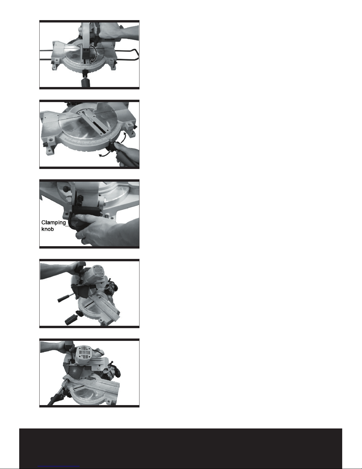
12. Secure work.
Where possible use clamps or a vice to hold the work. It is safer than using your
hand.
13. Do not overreach.
Keep proper footing and balance at all times.
14. Maintain tool with care.
Keep cutting tools sharp and clean for better and safer performance. Follow
instructions for lubrication and changing accessories. Inspect tool cord periodi-
cally and if damaged have them replaced by an authorised service facility. Inspect
extension cords periodically and replace if damaged. Keep handles dry, clean and
free of oil or grease.

15. Disconnect tools.
When not in use, before servicing and when changing accessories such as blades,
bits and cutters, disconnect tools from the power supply.
16. Remove adjusting keys and wrenches.
From the habit of checking to see that keys and adjusting wrenches are removed
from the tool before turning it on.
17. Avoid unintentional starting.
Ensure switch is in the “off” when plugging in.
18. Use outdoor extension leads.
When tool is used outdoors, use only extension cords intended for outdoor use
and so marked.
19. Stay alert.
Watch what you are doing. Use common sense. And do not operate tool when
you are tired.
20. Check damaged parts.
Before further use of the tool, it should be carefully checked to determine that it
will operate properly and perform its intended function. Check for alignment of
moving parts, binding of moving parts, breakage of parts, mounting and any other
conditions that may affect its operation. A guard or other part that is damaged
should be properly repaired or replaced by an authorised service centre unless
otherwise indicated in this instruction manual. Have defective switches replaced
by an authorised service centre. Do not use the tool if the switch dose not turn it
on and off.
21. Warning.
The using of any accessory or attachment other than those recommended in this
instruction manual may present a risk of personal injury.
22. Have your tools repaired by qualified person.
This electrical tool complies with the relevant safety rules. Repairs should only
be carried out by qualified persons using original spare parts, otherwise this may
result in considerable danger to the user.
HEALTH ADVICE
WARNING! When drilling, sanding, sawing or grinding, dust particles will be
produced. In some instances, depending on the materials you are working with,
this dust can be particularly harmful to you (e.g. lead from old gloss paint).
You are advised to consider the risks associated with the materials you are
workingwith and to reduce the risk of exposure. You should:
-- Work in a well-ventilated area.
-Work with approved safety equipment, such as those dust masks that are specially
designed to filter microscopic particles.

10” MITRE SAW SF2541
ADDITIONAL SAFETY INSTRUCTIONS FOR YOUR MITRE
SAW
1.Do not use saw blades, which are damaged or deformed.
2.Replace the table insert when worn.
3.Use only saw blades in these instructions and which conform to en 847-1.
4.Do not use saw blades manufactured from high speed steel.
5.Wear suitable personal protective equipment when necessary, this could include.
6.Connect the saw to a dust collecting devise when sawing wood.
7.Eye protection.
8.Respiratory protection to reduce the risk, of inhalation of harmful dust.
9.Gloves for handling saw blades (saw blades shall be carried in a holder wherever
practicable) and rough material.
10.Connect the saw to a dust collecting device when sawing wood.
11.Select the correct saw blade for the material to be cut.
12.Do not use the saw to cut other materials than those recommended by the manu-
facturer.
13.Do not use the saw without the guards in position, in good working order and
properly maintained.
14.Ensure that the arm is securely fixed when bevelling.
15.Keep the floor area around the machine level, well maintained and free of loose
materials e.g. chips and cut-offs.
16.Provide adequate general or localised lighting;
17.All personnel operating this machine must read these instructions and familiarise
themselves with the machines workings.
18.Use correctly sharpened saw blades. Observe the maximum speed marked on the
saw blade.
19.Ensure that any spacers and spindle rings used are suitable for the purpose as
stated by the manufacturer.
20.Retrain from removing any cut-offs or other parts of the workpiece from the cutting
area whilst the machine is running and the saw head is not in the rest position.
21.Ensure that the machine is always fixed to a bench, wherever possible.

SYMBOLS
Read the manual Warning Wear gloves
Wear dust mask,eye & ear protection
Conforms to relevant safety standards

10” MITRE SAW SF2541
1. SAFETY RELEASE LEVER
2. ON/OFF TRIGGER SWITCH
3. HANDLE
4. BACK COVER
5. MOTOR HOUSING
6. RETRACTABLE SAFETY GUARD
7. SAW HEAD LOCK PIN
8. TABLE EXTENSION ROD (ON BOTH SIDES)
9. TABLE TOP
10. TABLE INSERT
11. TABLE ANGLE POSITION LEVER
12. LOCKING MITRE HANDLE(FOR ROTATING TABLE TOP)
13. ANGLE SCALE
14. HORIZONTAL CLAMP
15. MOUNTING HOLE
16. TABLE EXTENSION RAIL CLAMP SCREW
17. DUST BAG

ACCESSORIES
Table extention rails: 2pcs
Clamp vice: 1pc
Dust bag: 1pc
Spanner: 2pcs
TECHNICAL DATA
Voltage:
Input power:
No load speed:
Blade diameter:
Blade bore:
Blade width:
Blade teeth:
Cutting capacities(mitre bevel):
0ox 0o:
0ox 45o:
45ox 0o:
45ox 45o:
Double insulation:
Net weight:
230V~50Hz
1600W
4500min-1
Ø250mm
Ø30mm
2.8mm
36
140x65mm
140x38mm
95x65mm
95x38mm
12.3kg
NOISE AND VIBRATION DATA
Sound pressure level: 96.8dB(A)
Sound power level: 109.8dB(A)
Vibration level: 2.5m/s2
RECOMMENDED SAW BLADE:
Ø250mm diameter Ø30mm bore diameter

10” MITRE SAW SF2541
ASSEMBLY
The saw must be stable and not move about
in operation. The saw must be mounted on
a level, firm work surface before using.
ROTARY TABLE LOCK HANDLE
To install the rotary table lock handle,place the
threaded stud at the outside of the threaded hole
and turn clockwise to tighten.(See fig2)
DUST EXTRACTION PORT
To reduce build up of saw dust and
maintain efficiency of cutting, the saw may be
connected to a workshop vacuum cleaner via
the dust outlet.
A dust bag is provided for use on your mitre saw.
To install it simply fit the dust bag over the exhaust
port on the upper blade guard. (See fig3)
To empty the dust bag, remove from the dust
exhaust port, open the dust bag by unzipping the
slide fastener.
NOTE:
To ensure optimal dust collecting, empty the dust
bag when it becomes filled to approximately 2/3
of its capacity.
TABLE EXTENSION ROD
To install table extension rod, insert ends of
extensions into the holes in either or both sides
of the base. Secure them in place by tightening
clamp screws on the front face of base. (See
fig4)
HORIZONTAL CLAMP
1.The Horizontal clamp can be fitted on either side
of the saw and is fully adjustable to suit the size of
the workpiece. (See fig5)
2.Do not operate the saw without clamping the
workpiece.
3.Make sure that the horizontal clamp securing
screws are tightened.
4.Warning: Always check your clamping position
does not interfere with any saw operation. Before
switching on, lower the saw head to make sure the
clamp clears the guard and saw head assembly.
Before using your mitre saw be sure to read
the instruction manual carefully.
Fig 2
Fig 3
Fig 4
Fig 5
Fig 6

OPERATION INSTRUCTIONS
Note:If you see some sparks flashing in the
ventilation slots, do not panic this is normal and
will not damage the machine.
1. MOUNTING THE SAW
The saw must be stable and not move about in
operation.Before use, the saw must be fixed to a
stable bench.Fixing holes are design on each foot
of the base.Put the machine on a flat plate(should
not be thicker than the bolts used, drill four holes
on the plate through fixing holes,then assemble
the screws through the holes,and secure the
mitre saw with the nuts.
2. RELEASING THE SAW HEAD
When you first open the box you will find that
the saw head is locked in the down position for
transportation purposes.
To release the head ready for operation apply
downward pressure and pull out the lock pin,
then turn 900 left or right to lock it in place. The
head will now be free to be raised gently to the
upper position. (See fig6)
3. STARTING THE SAW
Connect the machine to a power outlet, make
sure that the mains cable is clear of the blade and
base plate.
Push the safety button and squeeze the trigger
switch.
Allow the motor to reach full speed. When the
blade has reached maximum speed, unlock the
blade guard by operating the safety release
lever using your forefinger.(See point 1 Main
Diagram.)
4. TO MAKE A CUT
1.Position the material to be cut on the rotating
work support table, ensure it is firmly clamped so
that it will not move during cutting.
2.Push the safety button and press trigger and
allow the saw blade to run up the speed.
3.Still holding in the start trigger, use your right
hand forefinger to push the safety release lever
to the left. It will then be feasible to push the saw
head down by the handle. (See fig7)
4.Continue to move the saw head down smoothly
and make the cut exerting only gentle pressure
on the downward stroke, letting the Saw do the
Fig 7
Fig 8
Fig 9
Fig 10
Fig 11

10” MITRE SAW SF2541
work.
5. MITRE CUT (See fig8)
A mitre cut is made at 0o bevel and any mitre
angle in the range from 45o left to 45o right. The
table can be turned 45o both left and right from
the normal cross-cut 0 position to make a mitre
cut.
For most convenient operation, your mitre saw is
equipped with mitre indents for fast and accurate
mitre cuts of common mitre angles (Left: 45o, 30o,
22.5o, 15o; 0o; Right: 15o, 22.5o, 30o, 45o.)
1.Loosen the table lock handle by screwing it
anticlockwise.
2.Move the saw to the desired angle by pressing
the index lock lever and pushing the table lock
handle so that the table turns. Set at the desired
angle, and screw the lock handle clockwise and
make sure it is fully tightened before cutting.
6. BEVEL CUT USING THE HEAD TILT (see
fig9 & 10)
A bevel cut is made at 0O mitre and any bevel
angle in the range of 0O to 45O.
The saw can be moved from the normal 90O
- perpendicular position to an angled position
down to 45O from the horizontal, on the left only.
Loosen the clamping knob and tilt the saw head
to the left, until the desired angle is reached on
the bevel scale. Re-tighten the clamping knob
and make your cut.
7. COMPOUND CUT (See fig11)
A compound cut is a cut requiring both a mitre
setting and a bevel setting.
Compound mitre cuts can be achieved by setting
both the mitre and bevel angles simultaneously.
Follow the procedures for mitre and bevel cuts to
achieve the desired angles.
Fig 12
Fig 13
Fig 14
Fig 15
Fig 16
2
1

MAINTENANCE
Warning: Before making any adjust
ment, maintenance to the saw, make
sure that it is disconnected from mains
supply.
When all the adjustments, settings or
maintenance have been done, make sure that
all keys and wrenches have been removed
and that all screws, bolts and other fittings
are securely tightened.
PRECISION SETTING OF ANGLES
While the machine has been factory set, it is
advisable that the 0O setting of the rotary table
and the 90O perpendicular setting of the tilt be
checked, as these positions may have moved in
transit.
To confirm the 0O rotary table setting, set the
rotary table at 0O and tighten the rotary table lock
handle. Check that the angle between the straight
guide and the blade is 90O using an engineers
square (A, not supplied). (see Fig13). If the angle
requires adjustment, loosen two straight guide
clamp screws (as shown in Fig4) and align the
straight guide against the engineers square.
Retighten the clamp screws.
Similarly check that the angle of the blade to the
face of the table is 90O. If it is not vertical, use a
suitable slotted screwdriver, loosen the 90O screw
(See Fig 12 No 1), set to the correct position and
re tighten the screw.
The 45O can also be adjusted. First check the
angle with a 45O set square (not provided and see
Fig 15). To adjust, loosen the 45O screw (See Fig
12 No 2), set to correct angle and re tighten the
screw.
Note:
The position of bevel scale pointer may have
moved in transit or after use. Use a screwdriver
to adjust it if necessary.
CHANGING THE SAW BLADE
Warning: Disconnect the saw from the
power supply.
Loosen and remove the blade securing bolt and
outer flange with the spanners provided. (See fig
16)
Fig 17

10” MITRE SAW SF2541
Note:
The blade securing bolt has a left hand thread.
Remove the blade, (we recommend the use of a
stout glove for this). Clean any saw dust and debris
from the arbor and saw blade securing flanges.
To refit the blade follow the above procedure in
reverse order. If you take the inner flange off to
clean re-fit as shown in fig17.
MOVING THE SAW
1.When transporting the saw between locations
make sure that: 1. The saw head is locked in the
lower position.
2.The rotary table lock handle, the head tilt
clamping knob and the slide rod-locking lever are
all securely tightened.
3.You use the transportation handle to lift the saw.
Do not lift the saw by the switch handle.
ENVIRONMENTAL PROTECTION
Waste electrical products should not be
disposed of with household waste. Please
recycle where facilities exist. Check with
your Local Authority or retailer for recycling
advice.

PLUG REPLACEMENT
The fuse in the main plug of your power tool
should always be replaced with one of identical
rating.
Check the voltage given on your power tool
matches the supply voltage.
The power tool is supplied with a fitted plug,
however if you should need to fit a new plug
follows the instruction below.
IMPORTANT
The wire in the mains lead are coloured in
accordance with the following code:
Blue ---Neutral
Brown ---Live
The wire that is coloured blue must be connected
to the terminal that is marked with the letter N.
The wire that is coloured brown must be
connected to the terminal that is marked with the
letter L.
A 13AMP (BS1363 or BS1363/A) plug must be
used and a 13 AMP fuse must be fitted.
13 AMP
FUSE
BROWN
L (LIVE)
BLUE
N (NEUTRAL)
OUTER
SLEEVE CABLE GRIP

10” MITRE SAW SF2541
Declaration of Conformity
We, Importer
Screwfix Direct Ltd
Mead Avenue
Houndstone Business Park
Yeovil
BA 22 8RT
Declare that the product
MITRE SAW
SF2541
Complies with the essential health and safety requirements of the following directives:
89/336/EEC, 93/68/EEC.–EMC Directive.
73/23/EEC, 93/68/EEC.–Low Voltage Directive
98/37/EC.–Machinery Directive.
Standards and technical specifications referred to:
EN 61029-1:2000 +A11 +A12
EN 61029-2-9:2002
EN 55014-1:2000 +A1 +A 2
EN 55014-2:1997 +A1
EN 61000-3-2:2000
EN 61000-3-11:2000
2005
Authorised Signatory
Date: 09/15/05
Signature:
Name: Peter Harries
Screwfix Direct Ltd
Quality Manager

Table of contents
Other Titan Saw manuals

Titan
Titan TTB689CSW Installation manual

Titan
Titan TTB703SSW User manual

Titan
Titan SF210JSL Installation manual

Titan
Titan ttb554tas User manual

Titan
Titan TTB286CSW Installation manual

Titan
Titan TTB911CSW User manual

Titan
Titan SF08N5 Installation manual

Titan
Titan TTB287CSW Installation manual

Titan
Titan TTI880RSP User manual

Titan
Titan TTB867JSW User manual

Titan
Titan TTB599BNS User manual

Titan
Titan SF185R2 Installation manual

Titan
Titan SF16G User manual

Titan
Titan SF10N1 Installation manual

Titan
Titan TTB763TAS User manual

Titan
Titan SF2841 Installation manual

Titan
Titan TTB364BDS Installation manual

Titan
Titan TTB881RSP User manual

Titan
Titan TTB689CSW Installation manual

Titan
Titan TTB545SSW User manual