5
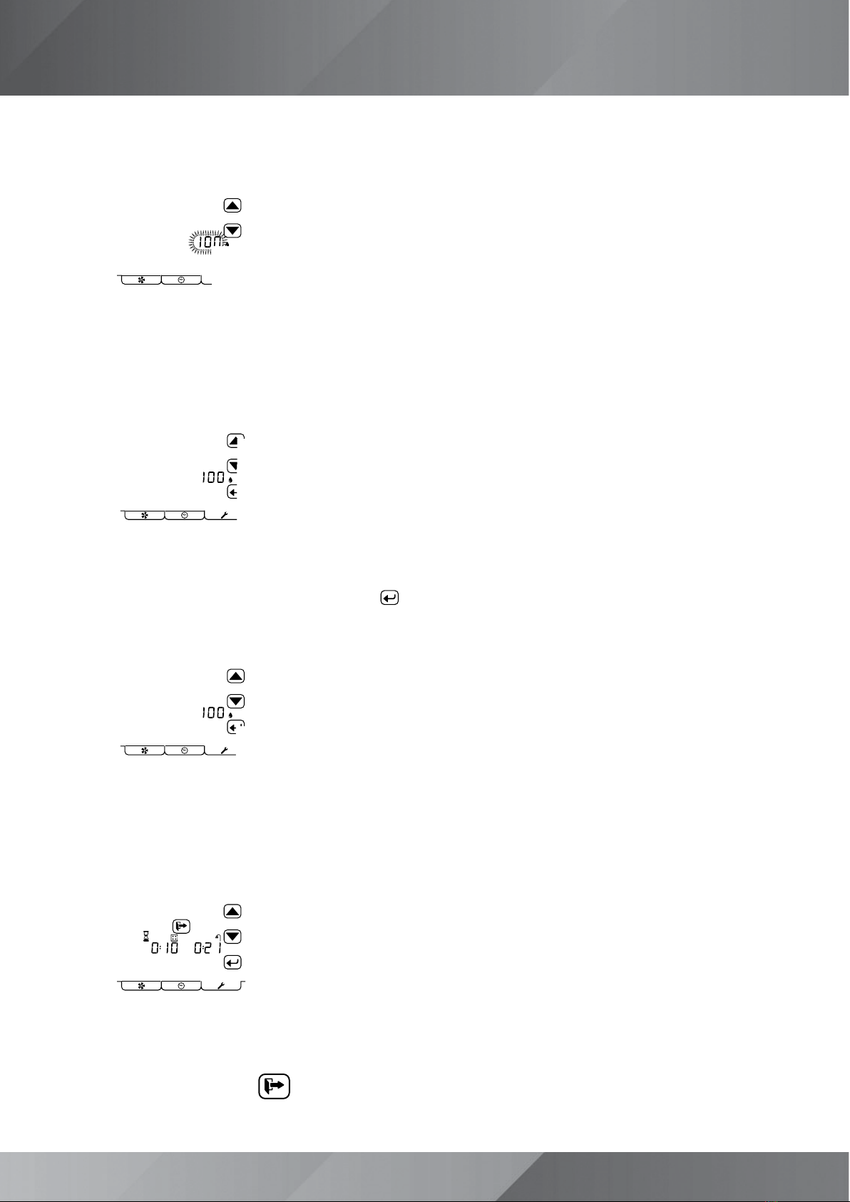
•Using the up and down arrows, indicated below, change the speed to a level that will provide the expected flow
rate. The speed % will change as you increase / decrease.
•Measure the flow rates in the kitchen & wet rooms, totalling up the measured figures
• If the total is greater than the required total Extract Continuous dwelling rate*, slow the unit down
• If the total is less than the required total Extract Continuous dwelling rate*, speed the unit up
• Keep changing the speed until the total required Extract Continuous dwelling rate* is achieved
*As the rates are minimums aim slightly higher approx. 1-2 l/s. If the reading is excessive it will result in excess noise and
increased power consumption
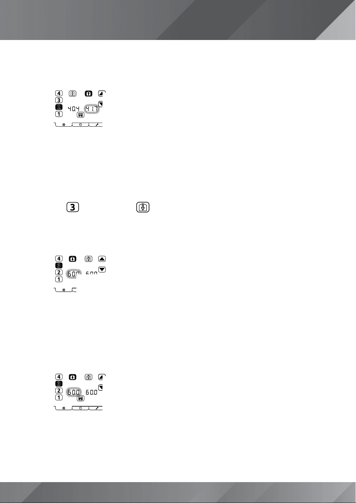
•Press the icon followed by the
icon, this will put the unit into the Supply Boost setting mode, as
below. The figure pointed at below will be flashing:
•Using the up and down arrows, indicated below, change the speed to a level that will provide the expected flow
rate. The speed % will change as you increase / decrease.
•Measure the flow rates in the habitable rooms, totalling up the measured figures
• If the total is greater than the required total Supply Boost dwelling rate*, slow the unit down
• If the total is less than the required total Supply Boost dwelling rate*, speed the unit up
• Keep changing the speed until the total Supply Boost dwelling rate* is achieved