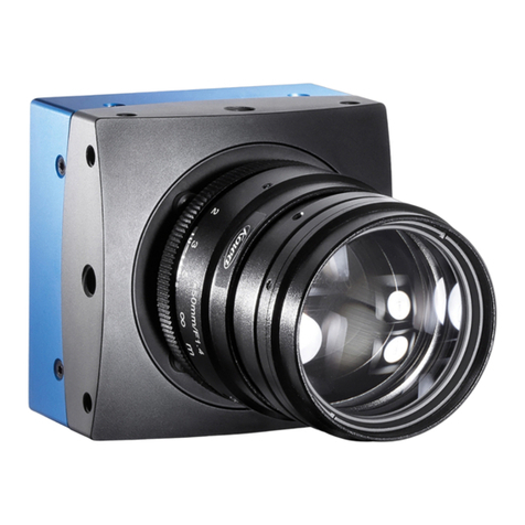
TKH ECO Series User manual

-~
ARTISAN
®
~I
TECHNOLOGY
GROUP
Your definitive source
for
quality
pre-owned
equipment.
Artisan Technology
Group
Full-service,
independent
repair
center
with
experienced
engineers
and
technicians
on staff.
We
buy
your
excess,
underutilized,
and
idle
equipment
along
with
credit
for
buybacks
and
trade-ins
.
Custom
engineering
so
your
equipment
works
exactly as
you
specify.
•
Critical
and
expedited
services
•
Leasing
/
Rentals/
Demos
• In
stock/
Ready-to-ship
•
!TAR-certified
secure
asset
solutions
Expert
team
ITrust
guarantee
I
100%
satisfaction
All
tr
ademarks,
br
a
nd
names, a
nd
br
a
nd
s a
pp
earing here
in
are
th
e property of
th
e
ir
r
es
pecti
ve
ow
ner
s.
Visit our website - Click HERE

Manual ECO series
eco204, eco267, eco274, eco285, eco414, eco415, eco424,
eco445, eco618, eco625, eco655

Content
1 Company information 6
1.1 Standards 6
1.2 Disclaimer 6
1.3 Copyright notice 7
2 Legal information 8
2.1 Europe 8
2.2 USA and Canada 8
3 Getting started 9
3.1 Content of camera set 9
3.2 Power supply 9
3.3 Camera status LED codes 9
3.4 Software 10
3.4.1 SVCapture 2 10
3.4.2 Firmware update 12
3.4.3 GigE IP Setup 13
4 Connectors 14
4.1 GigE Vision 14
4.1.1 Network (TCP/IP) 14
4.1.2 XML files 16
4.2 Input / output connectors 17
4.2.1 Hirose™ 12-pin connector layout 17
5 The ECO 18
5.1 The SVCam ECO Series: Extremely small 18
5.2 GigE-Vision features 18
6 Feature description 19
6.1 Basic features 19
6.1.1 Global shutter 19
6.1.2 Rolling shutter 20
2

6.1.3 Exposure 22
6.1.4 Exposure speed 22
6.1.5 Acquisition and processing time 22
6.1.6 Auto exposure 23
6.1.7 Bit depth 24
6.1.8 Color 25
6.1.9 Resolution 26
6.1.10 Offset 26
6.1.11 Gain 26
6.1.12 Binning 27
6.1.13 Decimation 28
6.1.14 Burst mode 30
6.2 Camera features 31
6.2.1 Basic capture modes 32
6.2.2 System clock frequency 35
6.2.3 Temperature sensor 36
6.2.4 Read-out control 36
6.2.5 Look-up table 37
6.2.6 ROI / AOI 39
6.2.7 PIV 39
6.2.8 Pixel clock frequency selection 40
6.2.9 Predefined configurations (user sets) 40
6.3 I/O Features 42
6.3.1 GenICam 42
7 Specifications 44
8 Dimensions 45
9 Terms of Warranty 46
10 FAQ 49
11 Glossary of terms 50
3

List of figures
Fig.: 3-1: Camera status LED codes 9
Fig.: 4-1: RJ45 socket connector 14
Fig.: 4-2: Data reduction with jumbo frames 14
Fig.: 4-3: Connecting multiple cameras on multi NICs 15
Fig.: 4-4: Illustration of connecting multiple cameras by a switch 15
Fig.: 4-5: Camera casting to multiple receivers (multicast) 16
Fig.: 6-1: Rolling shutter lines light sensitivity versus time 21
Fig.: 6-2: Acquisition and processing time 23
Fig.: 6-3: Sensor with Bayer pattern 25
Fig.: 6-4: Dark noise cut off by the offset 26
Fig.: 6-5: Noise caused by too much gain 27
Fig.: 6-6: Vertical binning 28
Fig.: 6-7: Horizontal binning 28
Fig.: 6-8: 2x2 binning 28
Fig.: 6-9: Horizontal decimation 29
Fig.: 6-10: Vertical decimation 29
Fig.: 6-11: Decimation on color sensors 29
Fig.: 6-12: Basic capture modes - free running 32
Fig.: 6-13: Basic capture modes - triggered mode (pulse width with
overlap) 33
Fig.: 6-14: Basic capture modes - triggered mode (pulse width
without overlap) 33
Fig.: 6-15: Mode 1: External trigger with pulse width exposure con-
trol (non-overlap) 34
Fig.: 6-16: Mode 1: External trigger with pulse width exposure con-
trol (overlap) 35
Fig.: 6-17: Mode 1: External trigger with programmable exposure
time (non-overlap) 35
Fig.: 6-18: Mode 1: External trigger with programmable exposure
time (overlap) 35
Fig.: 6-19: Illustration of physical data stream in time 36
Fig.: 6-20: Custom LUT adding contrast to the mid-tones 37
Fig.: 6-21: Several gamma curves comparable to a LUT 38
Fig.: 6-22: AOI on area sensor 39
Fig.: 6-23: PIV mode flash timing 39
4

1 Company information
SVS-Vistek GmbH
Ferdinand-Porsche-Str. 3
82205 Gilching
Germany
Tel.: +49 (0) 8105 3987-60
Fax: +49 (0) 8105 3987-699
Mail: [email protected]m
Web: https://www.svs-vistek.com
1.1 Standards
This manual is based on the following standards:
lDIN EN 62079
lDIN EN ISO 12100
lISO Guide 37
lDIN ISO 3864-2
lDIN ISO 3864-4
lDIN ISO 16016:2002-5
1.2 Disclaimer
This manual contains important instructions for safe and efficient handling of
SVCam products. This manual is part of the product and must be kept access-
ible in the immediate vicinity of the product for any person working on or with
this product .
Read carefully and make sure you understand this manual prior to starting any
work with this product . The basic prerequisite for safe work is compliant with all
specified safety and handling instructions.
Accident prevention guidelines and general safety regulations should be
applied.
Illustrations in this manual are provided for basic understanding and can vary
from the actual model of this product . No claims can be derived from the illus-
trations in this manual.
The product in your possession has been produced with great care and has
been thoroughly tested. Nonetheless, in case of any complaint, please contact
your local SVS-VISTEK distributor. You will find a list of distributors in your area
on www.svs-vistek.com
1 Company information 6

1.3 Copyright notice
Forwarding and duplicating of this document, as well as using or revealing its
contents are prohibited without written approval. All rights reserved with regard
to patent claims or submission of design or utility patent.
1 Company information 7

2 Legal information
Errors and omissions excepted.
These products are designed for industrial applications only. Cameras from
SVS-Vistek are not designed for life support systems where malfunction of the
products might result in any risk of personal harm or injury. Customers, integ-
rators and end users of SVS-Vistek products might sell these products and
agree to do so at their own risk, as SVS-Vistek will not take any liability for any
damage from improper use or sale.
2.1 Europe
This device is CE tested, rules of EN 55022:2010+AC2011 and EN61000-6-
2:2005 apply.
The product is in compliance with the requirements of the following European
directives:
l2014/30/EU Electromagnetic compatibility (EMC)
l2011/65/EU Restriction of the use of certain hazardous substances in elec-
trical and electronic equipment (RoHS)
All SVS-VISTEK products comply with the recommendation of the European
Union concerning RoHS Rules.
2.2 USA and Canada
This device complies with part 15 of the FCC Rules. Operation is subject to the
following conditions: (1) This device may not cause harmful interference, and
(2) this device must accept any interference received, including interference
that may cause undesired operation.
NOTICE This equipment is compliant with Class A of CISPR 32. In a residential
environment this equipment may cause radio interference.
This equipment has been tested and found to comply with the limits for a Class
A digital device, pursuant to part 15 of the FCC rules.
It is necessary to use a shielded power supply cable. You can then use the
“shield contact” on the connector which has GND contact to the device housing.
This is essential for any use. If not done and the device is destroyed due to
Radio Magnetic Interference (RMI) WARRANTY is void!
lPower: US/UK and European line adapter can be delivered. Otherwise use
filtered and stabilized DC power supply.
lShock & vibration resistance is tested. For detailed specifications refer to
the section on specifications ("Specifications" on page 44).
2 Legal information 8

3 Getting started
3.1 Content of camera set
lCamera
lPower supply (if ordered / option)
lDVD
l3D CAD files
lManuals
lSoftware: GigE-Kit (Win 32bit /64bit & Linux)
3.2 Power supply
Connect the power supply with the Hirose connector.
NOTICE This camera does not support hotplugging.
>First connect the data cable.
>Then connect power supply.
When using your own power supply (voltage range 10 -25 V DC) see also
Hirose 12-pin for a detailed pin layout of the power connector. For power input
specifications refer to "Specifications" on page 44.
3.3 Camera status LED codes
On power up, the camera will indicate its current operation status with a flashing
LED on its back. The LED will change color and rhythm.
The meaning of the blinking codes translates as follows:
Fig.: 3-1: Camera status LED codes
3 Getting started 9

3.4 Software
More information, documents, release notes, latest software and
manuals can be downloaded in the SVS-Vistek download area.
INFO Depending on your camera model, several software packages apply.
3.4.1 SVCapture 2
SVCapture 2.x is a XML based software tool. It provides the possibility to con-
trol a GenICam based camera. The image result of any modification of a cam-
era’s adjustment is immediately visible, making it the ideal tool to optimize
camera adjustments.
SVCapture covers following interfaces:
lGigE Vision
l10 GigE Vision
lCamera Link
lUSB3
lCoaXPress
SVCapture is included in the SVCam Kit, you can download it for free from
SVS-Vistek download area. It is based on GenTL, which provides the possibility
to use the SVS-Vistek driver for third-party software.
INFO Refer to the SVCam Kit Quick Guide for details. You will find this document in
the download area as well. Generally, any GenICam based software package
should be able to run a SVS-Vistek camera (GigE Vision, USB3, Camera
Link).
NOTICE It is recommended to uninstall the existing version of SVCam Kit or SVCap-
ture before installing the new version. While installing, deactivate your fire-
wall and anti-virus programs.
Installation procedure
The SVCam Kit Quick Guide contains an extensive installation guide.
lDownload the SVCam Kit matching your operating system.
lDisable firewall and anti-virus programs.
lIf the interface is Camera Link or CoaXPress, install frame grabber driver
software first.
lUnpack and install SVCapture with the drivers required for your camera’s
interface type.
lEnable firewall and anti-virus programs.
lConnect your camera’s interface cable and power.
lStart SVCapture.
lSelect your interface type in the discovery dialogue, SVCapture should
show your camera after about 30 seconds.
3 Getting started 10

3 Getting started 11

3.4.2 Firmware update
Some features may not have been implemented in older software revisions. For
updating your camera firmware to the most recent version, you need the firm-
ware tool “Firmware Update Tool.exe” and the firmware file (download it from
website, login area) matching your camera model.
Execute firmware update
lDownload the GigE firmware tool and the firmware file from the SVS-Vistek
website.
lUnpack everything into any folder, e.g. “C:\temp”.
lEnsure proper network configuration.
lRun the GigE update tool.
lWhen the camera is displayed, choose camera by entering camera index,
e.g. 1 and press ENTER.
lMake sure the new firmware is located in the current folder.
By selecting the camera on the network, the firmware update tool will search the
current folder for matching firmware and start update process.
NOTICE Do not power off during the update process.
Wail until firmware update has been finished.
3 Getting started 12

3.4.3 GigE IP Setup
Your GigEVision camera needs a working network connection. Make sure the
camera is attached to the network and is powered on. Make sure everything is
plugged in properly and that the firewall settings are not blocking the connection
to the camera or SVCapture.
3 Getting started 13

4 Connectors
Cameras from SVS-Vistek feature a combined I/O and power supply connector
(Hirose) and a data connector.
4.1 GigE Vision
4.1.1 Network (TCP/IP)
Address Assignment
By default, the camera does not have a persistent IP address.
When forcing an IP address by using the PC internal network dialog, changes
are only valid until the next restart of the Camera.
For a peer-to-peer connection of a GigE camera to a PC a network address
assignment based on LLA (Local Link Address) is recommended. This involves
a network mask “255.255.0.0” as well as a fixed preamble “169.254.xxx.xxx” of
the network address range. A GigE camera will fall back to LLA when no DHCP
server is available and no fixed network address was assigned to the camera.
Fig.: 4-1: RJ45 socket connector
Jumbo frames
The transport efficiency in the streaming channel can be improved by using
“jumbo frames”. This will reduce overhead caused by maintaining header data
upon each data packet sent. Jumbo frames increase the data size per Ethernet
packet.
Fig.: 4-2: Data reduction with jumbo frames
INFO Higher packet sizes require network cards that support jumbo packets.
Lost packets
In accordance with the TCP protocol, lost or corrupted packets will be resent.
4 Connectors 14

NOTICE Resends result in higher consumption of bandwidths and will lead to drop
frames. High quality cables prevent resends.
Connecting multiple cameras
Multiple GigE cameras can be connected to a PC either via a switch or using
dual or quad port network interface connectors (NIC).
Fig.: 4-3: Connecting multiple cameras on multi NICs
Multiple cameras connected by a switch
To connect multiple cameras by a switch, the switch must be managed. It might
also be necessary to operate the cameras in an “inter packet delay” applying a
smother image data stream.
Fig.: 4-4: Illustration of connecting multiple cameras by a switch
Dual GigE connection is not supported when using a switch.
4 Connectors 15

NOTICE Performance might be lost using multiple Cameras on a single port NIC.
Multicast
When images from a single camera need to be delivered to multiple PCs, mul-
ticast (RFC 2236) is used. A switch receives an image data stream from a cam-
era and distributes it to multiple destinations in this mode.
Since a GigE camera always needs a single controlling application, there will be
only one master application. The controlling master application has to open a
camera in multicast mode (IP 232.x.x.x for local multicast groups) in order to
allow other applications to connect to the same image data stream. Other applic-
ations will become listeners to an existing image data stream. They do not have
control access to the camera; however, potential packet resend requests will be
served in the same manner as for the controlling application.
Fig.: 4-5: Camera casting to multiple receivers (multicast)
4.1.2 XML files
According to the GigE Vision standard a GigE camera provides an XML file that
defines the camera’s capabilities and current settings.
The XML file can be processed by software like SVCapture allowing displaying
and saving it to disk. Settings can also be saved and restored on the Camera
internal EEPROM.
4 Connectors 16

4.2 Input / output connectors
NOTICE Make sure your external power supply meets specifications.
Voltage must not exceed 25 V.
4.2.1 Hirose™ 12-pin connector layout
The Hirose connector provides the connectors to power, inputs and outputs.
INFO For information about switching lights from inside the camera, refer to "LED
strobe control".
Specification
Type HR10A-10R-12P
Mating Connector HR10A-10P-12S
NOTICE The PoE (Power over Ethernet) versions do not support RS232 on pins 3,
4.
4 Connectors 17

5 The ECO
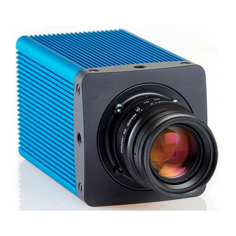
5.1 The SVCam ECO Series: Extremely small
A SVCam-ECO fits into any type of application. The SVCam-ECO series
impresses with its minimal footprint. And that even without compromising on
performance.
One of the world’s smallest GigE vision cameras
Unparalleled flexibility with an excellent price-performance ratio: This is how
one best would describe the SVCam-ECO series. Comprising 88 different vari-
ants, the cameras use well-known Sony CCD sensors with resolution ranging
from VGA to 5 megapixel. The cameras are among the smallest industrial cam-
eras and were specifically developed to provide the highest frame rates paired
with excellent signal-to-noise ratio. Supporting GigE Vision and GenICam stand-
ards, the SVCam-ECO series opens up new possibilities for integrating into
your specific applications.
5.2 GigE-Vision features
GigE Vision is an industrial interface standard for video transmission and device
control over Ethernet networks. Being an industry standard, it facilitates easy
and quick interchangeability between units, shortening design cycles and redu-
cing development costs. It provides numerous software and hardware advant-
ages for machine vision.
lCost effective
lWide range of „off the shelf“ industrial-standard plugs and cables
lHigh bandwidth data transfer rate (120 MB/sec per output)
lUp to 100 m range without additional switch
lWide range of applications in image processing
lRemote service capability
lGenICam compliant
lSDK for Windows XP/10 (32/64 bit), and Linux
lARM support (ARM/Jetson)
lSDK with GenTL support
5 The ECO 18

6 Feature description
This chapter covers features of SVCam cameras. Not every feature might be
supported by your specific camera model. For information about the features of
your specific model, please refer to the specifications area of our website with
your exact model.
https://www.svs-vistek.com/en/industrial-cameras/svs-svcam-searchresult.php
This chapter covers features of SVCam cameras. Not every feature might be
supported by your specific camera model. For information about the features of
your specific model, please refer to the specifications area with your exact
model.
6.1 Basic features
6.1.1 Global shutter
The shutter is describing the functionality of exposing the light sensitive pixels
of the sensor to light for a limited time. With global shutter all pixels are exposed
to light at the same time for the same time.
All pixels will be exposed to light at the same starting point, and all pixel light
exposure will stop at the same time. Fast moving objects will be captured
without movement distortion, except motion blur if the moving object is so fast
that the same point of the object covers different pixels at start and end while
exposing.
Using flash with global shutter is straight forward: make sure your flash is on
while shutter is open, thus all pixels are exposed to light the same time. You
might flash at any time within exposure time.
6 Feature description 19
This manual suits for next models
11
Table of contents
Other TKH Digital Camera manuals

