VVG VNG 152 User manual

VNG 152VNG 152
VNG 152VNG 152
MULTI151MULTI151
MULTI151MULTI151
MULTI151MULTI151
BEDIENUNGSANLEITUNG
instruction manual
Blindnietgewindebolzen
blind rivet bolts
Blindnietgewindebolzen
blind rivet bolts
Blindniete
blind rivets
Blindnietmuttern
blind rivet nuts
Blindnietmuttern
blind rivet nuts
MULTI151
VNG 152
VNG 152VNG 152


ALLGEMEINE INFORMATIONEN
general information
Vielen Dank für den Kauf dieses hochwertigen Blindniet-Werkzeuges zur
Verarbeitung von Blindniete und/oder Blindnietmuttern und -gewindebolzen.
Thank you for buying this first class blind rivet tool
for blind rivets and/or blind rivet nuts and -bolts.
ii
Damit Sie lange und gewinnbringend mit dem Gerät arbeiten können,
bitten wir Sie sich unbedingt die Zeit zu nehmen, diese Anleitung vor
der ersten Inbetriebnahme genau zu lesen!
Sie vermeiden so unnötige Fehler bei der Bedienung und erhalten
wertvolle Hinweise zur richtigen und notwendigen Pflege.
Therewith you can use the tool profitable for a long
time, we like to ask you to read this instruction
manual accurately before using it the first time.
This will avoid unnecessary mistakes and provide
valuable details for the correct care of the tool.
- Lagern und transportieren Sie das Werkzeug möglichst generell in der
Originalverpackung - so ist es optimal geschützt!
- Das Werkzeug nicht werfen oder fallen lassen!
Nicht als Schlagwerkzeug verwenden!
- Jeder Anwender muss im Umgang mit dem Werkzeug geschult sein
- Reparaturen, die über Wartung, Pflege und den Austausch von Verschleißteilen
hinaus gehen, dürfen nur von unserer Werkstatt vorgenommen werden.
Tragen Sie bei Wartung und Verarbeitung grundsätzlich eine Schutzbrille!
Always wear eye protection glasses while using
or repairing this tool!
- Use the original package for transportation and storage
in general to guarantee ideal shelter!
- Never throw or drop the tool! Do not use the tool as
a hammer!
-Every operator must be educated in the use of this tool
- Repairs exceeding maintainance and the change of
wear parts should be done only by our service center.
3
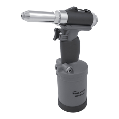
Die Funktion der beiden Werkzeuge ist denkbar einfach.
Sie basiert auf einer kontinuierlichen Pumpbewegung
und dem abschließenden Entspannen der Hydraulik.
Das Hydrauliksystem ist in sich geschlossen und wartungsfrei.
Sollte Öl austreten, kontaktieren Sie Ihren Fachhändler oder unser Verkaufsteam
und senden Sie das Werkzeug umgehend an unser SERVICE CENTER.
The hydraulic system is self-contained and free of maintenance.
If you orserve a leak of oil please contact your local dealer or our
sales team to send the tool to our SERVICE CENTER immediately.
4
DIE WERKZEUGE
the tools
Die MULTI 151 und VNG 152 zeichnen sich durch Ihre
hervorragende Übersetzung und den leichten Wechsel der
Umrüstteile aus.
The MULTI 151 and VNG 152 feature brilliant power gear
ratio and an easy way of changing the conversation parts.
Beachten Sie unbedingt: Stellen Sie die Pumpbewegung immer
ein, sobald Sie einen Widerstand spüren. Detaillierte Vorgehens-
weisenentnehmen Sie bitte den weiteren Beschreibungen in
diesem Heft!
Operating the tools is as easy as possible. It bases on a continuous
pumping action and the concluding relieve of the hydraulic component.
Please note that the pumping must stop absolutely when you feel a
resistance! Detailed descriptions follow on further pages of this manual.

Blindnietgewindebolzen
blind rivet bolts
Aluminium
Stahl
Edelstahl
M4 - M8
M4 - M8
M4 - M5
aluminium
steel
stainless steel
Please consider, that the VNG 152 and MULTI 151 are constructed for the following
blind rivet products:
Bitte beachten Sie, dass VNG 152 und MULTI 151 ausschließlich für die Verarbei-
tung der folgenden Blindnietprodukte verwendet wird:
Aluminium
Stahl
Edelstahl
Kupfer
Blindniete
blind rivets
Blindnietmuttern
blind rivet nuts
3,0-6,4 mm
3,0-5,0 mm
3,0-5.0 mm
3,0-5,0 mm
aluminium
steel
stainless steel
copper
Aluminium
Stahl
Edelstahl
M3 - M8
M3 - M8
M3 - M5
aluminium
steel
stainless steel
Make sure that the correct conversation parts for the chosen fastener (nose
pieces, mandrells and sleeves) are assembled.
Stellen Sie vor Gebrauch sicher, dass sie immer den zum zu verarbeitenden
Verbinder passende Umrüstteile wie Mundstücke, Gewindedorne oder -hülsen
montiert haben.
5
DIE WERKZEUGE
the tools
MULTI 151 + VNG 152
MULTI 151 + VNG 152
MULTI 151

Tooling blind rivets
After the fitting nose piece is installed hand-tight,
you can insert the mandrel of the rivet.
Place the rivet into the accurately prepared
drill-hole and start the tooling. Rivet and tool
must be pressed against the component strongly.
The clamping jaws grip on the rivets mandrel by
small, continuous pump movements with the
tools handle bars until the mandrel separates on the
breaking point.
If one cycle of approx. 10-12 stokes is not enough to place the rivet, press
the tool only once and release the toll in pressed position by pushing the
release button. After that you can continue the handling.
After the mandrel broke off, it has to be removed from the tool. For this point
the tool with the nose piece to the bottom and press the release button. So
the remaining part of the mandrel drops out.
Nachdem der Dorn an der Sollbruchstelle
abgerissen ist, muss dieser aus dem Werk-
zeug entfernt werden.
Halten Sie dazu das Werkzeug mit dem
Mundstück nach unten, betätigen die Hebel
und drücken den Entlüftungsknopf, so dass
die Spannbacken den Restnietdorn freigeben
und dieser aus dem Gerät fällt.
7
BLINDNIETE (MULTI 151)
blind rivets (MULTI 151)

Entlastungsknopf
Release button
Spannbacken
clamping jaws
Druckfeder
pressure spring
Mundstück
nose piece
Vordere Hülse
front sleeve
Spannhülse
sleeve
6
Verarbeitung Blindniete
Nachdem das korrekten Mundstück handfest montiert
wurden, kann der Blindnietdorn eingeführt werden.
Setzen Sie den Blindniet in die korrekt vorbereitete Bohrung des
Bauteils und starten Sie die Verarbeitung.
Drücken Sie Niet und Werkzeug dabei fest gegen das Bauteil.
Durch kleine, regelmäßige Pumpbewegungen greifen die Spannbacken
auf dem Blindnietdorn und reißen diesen an der Sollbruchstelle ab.
Sollte ein Durchlauf (ca. 10-12 Hübe) nicht ausreichen um den
Niet vollständig zu setzten, betätigen Sie das Werkzeug nur noch einmal
und entlasten es in gedrückter Position durch Druck auf den Entlastungs-
knopf. Danach können Sie den Niet erneut greifen und weiter verarbeiten.
BLINDNIETE (MULTI 151)
blind rivets (MULTI 151)
MULTI 151

- Entfernen Sie zunächst die Vordere Hülse (1)
- Schrauben Sie die Spannhülse (in der sich die Spann-
backen befinden ) und die Druckfeder vom der Spannme-
chanismus (2)
- Entnehmen Sie die Spannbacken
- Betätigen Sie das Werkzeug bis der Spannmechanismus
voll ausgefahren ist
- Halten Sie die Spannhülse mit dem stärkeren Teil nach
unten und lassen nacheinander die drei Spannbacken hinein
gleiten (3)
Beachten Sie, dass nur die Rückseiten der Spannbacken
etwas gefettet sein sollten!
- Danach wird die Druckfeder über die Spannhülse mit den
montierten Spannbacken gestülpt.
- Im Anschluss daran wird die Spannhülse wieder handfest
auf den Spannmechanismus geschraubt (4)
- Zuletzt erfolgt die Montage der vorderen Hülse.
8
1
2
3
4
- Remove the front sleeve (1)
- Unscrew the clamping sleve with the thre clamping jaws
and the pressure spring from the gripping mechanism (2)
- Extract the clamping jaws from the clamping sleeve
- Operate the tool until the gripping mechanism is extended
to the maximum
- Hold the clamping sleeve with the wider part to the bottom
and let the three clamping jaws slide in one after the other (3)
Please note, that only the back of the clamping jaws must
be lubricated!
- After positioning the clamping jaws, put the pressure
spring over the clamping sleeve.
- Following to this screw in the clamping sleeve hand-tight
to the gripping mechanism again. (4)
- Finally you have to assemble the front sleeve.
Change of clamping jaws
Wechsel Spannbacken
BLINDNIETE (MULTI 151)
blind rivets (MULTI 151)

Gehäuse
housing
Mundstück
nose piece X
Change of nose piece
- Remove the assembled nose piece by unscrewing against the anti-clockwise
rotation.
- Operate the tool until it is strained to the maximum (dimension X between
cover and housing approx. 22mm)
- Screw in the new nose piece hand tight and release the tool by pressing
the release button
9
Entlastungsknopf
release button
Wechsel Mundstück
- Betätigen Sie das Werkzeug bis das Mundstück von den Spannbacken
entlastet ist (Maß X zwischen Abdeckung und Gerätegehäuse = max.
ca. 22mm)
- Schrauben Sie das nicht benötigte Mundstück aus der vorderen Hülse
- Schrauben Sie das benötigte Mundstück in die vordere Hülse
- Entlasten sie das Werkzeug durch Druck auf den Entlastungsknopf.
Abdeckung
cover
BLINDNIETE (MULTI 151)
blind rivets (MULTI 151)

Entlastungsknopf
release button
Druckfeder
pressure spring
Vordere Hülse
front sleeve
Mundstückhalter
adapter for nose piece
Gewindedorn
mandrel
Mundstück Blindnietmutter
nose piece blind rivet nut
10
BLINDNIETMUTTERN /-GEWINDEBOLZEN
blind rivet nuts / bolts
Verarbeitung Blindnietmuttern / Blindnietgewindebolzen
Das Mundstück und der Gewindedorn muss entsprechend der jeweiligen
Blindnietmutternabmessung ausgewählt werden.(analoge Vorgehensweise bei
der Verarbeitung von Blindnietgewindebolzen mit den entsprechenden
Mundstücken und Gewindehülsen anstatt Gewindedornen).
Schrauben Sie die zu verarbeitende Blindnietmutter so auf den Gewindedorn,
dass die Mutter bündig am Mundstück anliegt.
Setzen Sie die Blindnietmutter in die korrekt vorbereitete Bohrung des
Bauteils und starten Sie die Verarbeitung. Drücken Sie Blindnietmutter und
Werkzeug dabei fest gegen das Bauteil.
Gewindedornaufnahme
adapter for mandrel

11
BLINDNIETMUTTERN /-GEWINDEBOLZEN
blind rivet nuts / bolts
Durch kleine, regelmäßige Pumpbewegungen beginnt die Blindnietmutter
sich zu verformen. Wenn die Mutter vollständig gesetzt ist, merken Sie einen
Widerstand - führen Sie dann KEINE weitere Pumpbewegung aus!
Entlasten Sie das Werkzeug mit gedrückten Griffen durch Druck auf den
Entlastungsknopf und drehen Sie den Mundstückhalter gegen den Uhrzeiger-
sinn bis der Gewindedorn aus der gesetzten Blindnietmutter herausgedreht ist
Tooling blind rivet nuts / blind rivet bolts
For handling blind rivet nuts the correct nose piece and mandrel must be
assembled (appropriate proceeding for handling of blind rivet bolts with nose
piece and threaded sleeve instead of the mandrel ).
Screw the blind rivet nut on the mandrel, so that it flushes on the nose piece.
Place the blind rivet nut into the accurately prepared drill-hole and start the
tooling. Blind rivet nut and tool must be pressed against the component
strongly.
By small, continuous pump movements the blind rivet nut starts to deform.
You will notice a resistance when the setting of the rivet nut is completed -
do NOT continue with the pumping movements in that moment!
Release the tool with compressed handle bars by pushing the release button
and turn the holder for nose pieces the against the anti-clockwise rotation
until the mandrel is unsrewed from the set blind rivet nut.

...Für Blindnietmuttern und Gewindeb
12
BLINDNIETMUTTERN /-GEWINDEBOLZEN
blind rivet nuts / bolts
Wechsel Gewindedorn (-hülse ) / Mundstück
- Entspannen Sie das Werkzeug durch Betätigung des Entlastungs-
knopfes bei gedrückten Griffen.
- Ziehen Sie das montierte Mundstück aus dem Mundstückhalter und
schauben Sie den Gewindedorn. Aus der Gewindedornaufnahme
(Achtung Linksgewinde!).
- Die Wiedermontage erfolgt in der entsprechend umgekehrten Reihen-
folge - beachten Sie zum korrekten Zusammenspiel die Skizze auf
Seite 10.
Change of mandrel (-sleeve) / nose piece
- Release the tool by pushing the release button with compressed
handle bars.
- Pull off the assembled nose piece from the holder for nose pieces
and unscrew the mandrel from the adapter for mandrels too.
(left-hand thread)
- The reassambling happens in invers order - consider for the draft on
page 10.

13
Umrüstung: Verarbeitung von Blindniete auf die Verarbeitung von
Blindnietmuttern (analog Blindnietgewindebolzen)
Entfernen Sie zunächst alle Bauteile, die zur Verarbeitung von
Blindniete montiert sind:
- Entspannen Sie das Werkzeug durch Betätigung des Entlastungs-
knopfes bei gedrückten Griffen.
- Drehen Sie das montierte Mundstück aus der vorderen Hülse
- Entfernen Sie dann nacheinander zunächst die vordere Hülse,sowie
die Führungshülse mit den darin enthaltenen Spannbacken (S.8)
Ersetzen Sie die demontierten Teile der Blindnietverarbeitung durch
die folgenden Teile zur Verarbeitung von Blindnietmuttern (-analog
Blindnietgewindebolzen)
- Schrauben Sie die Gewindedornaufnahme auf die Zugspindel
- Beachten Sie, dass die Druckfeder noch immer korrekt positioniert ist.
- Montieren Sie dann nacheinander Gewindedorn, vordere Hülse,
Mundstückhalter und das passende Mundstück.
UMBAU (MULTI 151)
convertion (MULTI 151)
Modification from handling of blind rivets to handling of blind rivet
nuts (blind rivet bolts)
Remove all spare parts for the handling of blind rivets at first:
- release the tool by pushing the release button with compressed
handle bars
- unscrew the assembled nose piece from the front sleeve
- remove one after the other the front sleeve as well as the clamping sleeve
with the included clamping jaws (S.8)
Replace these dismantled parts by the requested parts for blind rivet nuts
(and blind rivet bolts):
- screw the adapter for mandrels on the feed shaft
- consider that the pressure spring is still positioned correctly.
- assemble one after the other the mandrel, front sleeve, holder for nose
pieces and at last the nose piece.

3
4
5
6
7
8
9
10
11
12
1
2
3
4
5
6
7
311.151.000.010
311.151.000.007
311.151.000.009
311.151.000.001
311.151.000.008
311.151.003.003
311.151.003.004
311.151.003.005
311.151.003.006
311.151.003.008
311.151.002.003
311.151.002.004
311.151.002.005
311.151.002.006
311.151.002.008
Druckfeder
Gewindedornaufnahme
Abdeckung
Vordere Hülse
Mundstückhalter
Gewindedorn M3
Gewindedorn M4
Gewindedorn M5
Gewindedorn M6
Gewindedorn M8
Mundstück Blindnietmutter M3
Mundstück Blindnietmutter M4
Mundstück Blindnietmutter M5
Mundstück Blindnietmutter M6
Mundstück Blindnietmutter M8
Pressure spring
Adapter for mandrel
Cover
Front sleeve
Holder for nose piece
Mandrel M3
Mandrel M4
Mandrel M5
Mandrel M6
Mandrel M8
Nose piece rivet nut M3
Nose piece rivet nut M4
Nose piece rivet nut M5
Nose piece rivet nut M6
Nose piece rivet nut M8
Überprüfen Sie regelmäßig Verschleißteile wie z.B. Spannbacken
oder Gewindedorne auf ihren Zustand.
Please check all wear parts as for example clamping jaws or
mandrels regulary.
14
ERSATZTEILE
spare parts

Alle Teile der Hauptbaugruppe
dürfen nur von unserem Werkstatt
repariert werden.
All components from the main
assembly group may only be
repaired by our service center.
1
2
8
9
10
11
12
311.151.004.004
311.151.004.005
311.151.004.006
311.151.004.008
311.151.007.004
311.151.007.005
311.151.007.006
311.151.007.008
311.151.000.005
311.151.000.006
311.151.001.030
311.151.001.040
311.151.001.050
311.151.001.060
311.151.001.064
Gewindehülse Rifbolt M4
Gewindehülse Rifbolt M5
Gewindehülse Rifbolt M6
Gewindehülse Rifbolt M8
Mundstück Rifbolt M4
Mundstück Rifbolt M5
Mundstück Rifbolt M6
Mundstück Rifbolt M8
Spannhülse Blindniete
Spannbacken
Mundstck.Niete 3,0/3,2mm
Mundstck.Niete 4,0mm
Mundstck.Niete 4,8/5,0mm
Mundstck.Niete 6,0mm
Mundstck.Niete 6,4mm
Threaded s
Threaded s
Threaded s
Threaded s
leeve Rifbolt M4
leeve Rifbolt M5
leeve Rifbolt M6
leeve Rifbolt M8
Nose piece Rifbolt M4
Nose piece Rifbolt M5
Nose piece Rifbolt M6
Nose piece Rifbolt M8
Clamping sleeve blind rivets
Clamping jaws
Nose piece rivets 3,0/3,2mm
Nose piece rivets 4,0mm
Nose piece rivets 4,8/5,0mm
Nose piece rivets 6,0mm
Nose piece rivets 6,4mm
15
ERSATZTEILE
spare parts

Ihr Fachhändler vor Ort Your local dealer
This manual suits for next models
1
Table of contents
Other VVG Rivet Tools manuals