Titgemeyer MS 40A User manual

L
Fastening Technology
Riveting Tool
MS 40A
Operating Manual

2
Table of contents
Guiding instructions........................................................... 4
Cautions, instructions and procedural
sections in the operating instructions ................................... 5
Markings on the riveting tool ................................................ 6
Safety instructions ............................................................. 7
Basic requirements while dealing with
the riveting tool .................................................................... 8
Noise and vibration levels of the MS 40A ............................ 10
Description of the riveting tool ......................................... 11
Necessary tools .................................................................. 13
Storing the riveting tool ..................................................... 13
Preparing the riveting tool................................................. 14
Operating the riveting tool................................................. 17
Setting the blind rivet............................................................ 18
Changing the nose piece...................................................... 19

3
Maintaining the riveting tool.............................................. 20
Bleeding the hydraulic section, refilling hydraulic oil ............ 20
Changing the jaws ................................................................ 22
Adjusting the jaw case body................................................. 24
Table for torque values ......................................................... 25
Servicing and cleaning the riveting tool .......................... 26
Maintenance intervals ........................................................ 27
Trouble shooting................................................................. 28
Disposal of the riveting tool .............................................. 31
Technical data ..................................................................... 31
Guarantee ............................................................................ 32
List of parts ......................................................................... 33
Declaration of conformity .................................................. 35

4
Guiding instructions
The legislator prescribes that the user must be well trained for using com-
pressor-driven riveting tools. If desired, the training programme can be
conducted at TITGEMEYER in Osnabrück or directly at the client’s place.
This riveting tool is as per the latest technological standards. For the devi-
ce to function properly, it is necessary to operate it in an expertly manner,
with adherence to safety requirements.
Before using the riveting tool for the first time, read the guiding instruc-
tions carefully.
All the procedures necessary for the operation have been described in
these guiding instructions. You may carry out only those procedures,
which have been described here.
In case of obstructions, you may repair only those obstructions, which
have been marked with an O (Operator).
All the illustrations and position-codes in the individual diagrams take refe-
rence from the list of parts in the last pages.
For sizes of screws and threads you will find a table containing the torque
values on page 25 of the chapter “Maintening the riveting tool”.
Instruction
Technological level
Reading the guiding instructions
Procedures
Obstructions
Illustrations and position-codes
Table for torque values

5
Guiding instructions
H
E
Cautions, instructions and procedural sections in the
operating instructions
Please follow the instructions and safety informations.
In these operating instructions, some sections have been further illustra-
ted through diagrams
Please acquaint yourself well with these diagrams and their meanings:
Caution Hazard of injury! This marking indicates a potential hazard.
Attention Material damage! This marking points at a procedure, which
may cause damage to the riveting tool or the work-piece.
Note This marking indicates useful information.
•This point (•) marks every paragraph, which requires you to act by
yourself.
Attention Environmental hazard! This marking indicates a potential
environmental hazard.
Environmental
hazard

6
Guiding instructions
PRODUCTSERVICE
A
B
C
D
E
F
G
Markings on the riveting tool
This pictogram indicates that you must read the operating instructions
before using the riveting tool.
AMarking of the type
BSerial number
CCE-marking
DInstruction for reading the operating instructions
E Name of the manufacturer as well as the value of the maximum
operating pressure
FTÜV-Mark (safety checked)
GSupplier

7
Safety instructions
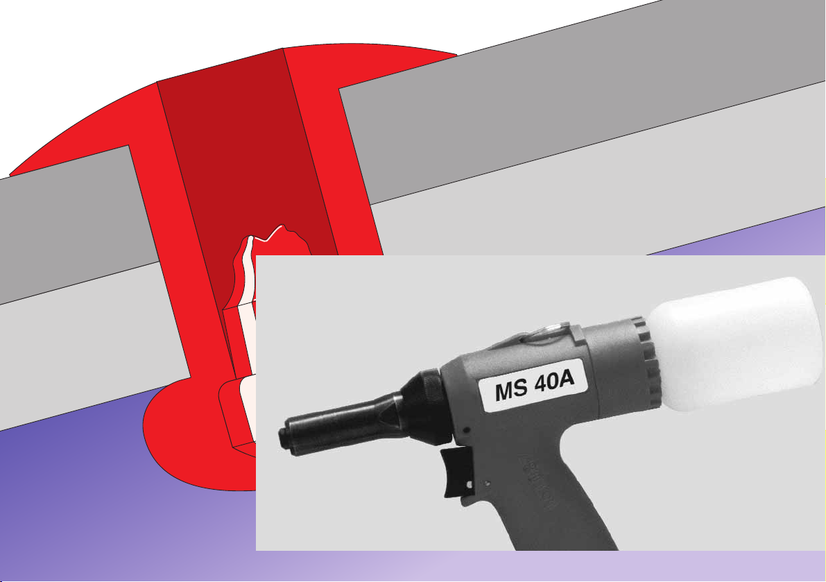
The riveting tool is meant exclusively for setting blind rivets.
The riveting tool MS 40A has been designed for setting all materials of
blind rivets with a shank diameter of 4.0 to 6.4 mm.
This riveting tool must be used only as a hand-held device!
The client is fully responsible for any modifications to the riveting tool!
Never throw away or drop the riveting tool!
Please take care that only clean and dry compressed air is let into the
riveting tool. Moisture and dirt can damage the riveting tool. Use only such
compressed air, which falls into class 2 of air quality as per ISO 8573-1.
Caution Hazard of injury because of explosion! Never use the riveting
tool in an atmosphere prone to explosions. Ensure that the
workplace is well lit and clean.
Hazard of injury due to the openly moving compressed air
hose. Connect and lay the compressed air hose properly.
Hazard of injury due to tripping over! Lay the compressed air
hose in such a way that nobody should trip over it.
Attention Material damage! The maximum operating pressure is 7 bar.
For increasing the durability of the riveting tool, it is recommen-
ded to fit a compressed air-maintenance unit in the compressed
air hose.
Application as per the purpose
Improper use
Clean and dry compressed air
H
E

8
Safety instructions
Basic requirements while dealing with the riveting tool
Caution Do not operate the riveting tool when it is directly pointing at
any person.
Follow the prevalent guidelines for the prevention of accidents
in the respective country.
Use only those fittings and hoses, which have been approved
for the operating pressure.
Disconnect the compressed air supply from the riveting tool at
the time of installation or maintenance.
Wear personal safety gear (safety glasses and safety helmet).
Attention Please pay attention to the information on the pack of the blind
rivet.
Use the riveting tool only at operating temperatures above 5°C
and 45°C.
For different diameters of the rivet shank, use the appropriate
nose piece, as prescribed.
Do not throw away the riveting tool.
H
E

9
Safety instructions
The operator may only carry out the maintenance and repair work descri-
bed in these operating instructions
Maintenance and service work not described in these operating instruc-
tions may only be carried out by trained specialists following instruction by
TITGEMEYER on the basis of the service instructions which also exist.
See the address on Page 34 for more information on service instructions
and training.
Note The manufacturer accepts no liability for damage resulting from
incorrect repairs or the use of spare parts from other sources.
At the time of leaving the workplace, do not leave the riveting tool with
pressure on.
Aguarantee is void, if any repair work carried out on the riveting tool has
lead to any damage of the riveting tool.
The riveting tool MS 40A has been checked and manufactured according
to European guidelines. The declaration of conformity can be found on the
second last page.
In addition to this, the riveting tool has been checked by the TÜV Product
Service GmbH, Hannover, and certified with a GS-mark.
Maintenance and servicing
Service instructions
Guarantee
Declaration of conformity
GS-checked

10
Safety instructions
Noise and vibration levels of the MS 40A
Noise level
The sound-emission level for workplaces is LPAI<70dB(A) as per
ISO 10843 and DIN EN 3744.
Vibration level
The effective value measured on acceleration with the handle, as per
ISO/FDIS 8662-11, is ahw<2,5m/s2.

11
6
6.1
4
3
2
1
Description of the riveting tool
The riveting tool MS 40A works according to a pneumatic-hydraulic prinzi-
ple.
It consists of the following operation-related components:
1Nose piece Serves for the correct reception of the blind
rivet – others are screwed in the bottom of the
valve housing
2Nose cap Conceals the jaw case body and the
jaw case
3Hydraulic The pneumatic and the hydraulic
housing units are located in the hydraulic housing
4Safety Prevents the spent mandrel from leaving the
mechanism tool
6Spent mandrel Serves the purpose of collecting
collector spent mandrels (with air-outlet (6.1)
)

12
Description of the riveting tool
Note The socket head screw (7) and the O-ring (8) are screwed tightly
into the grip. The socket head screw (7) must not be loosened,
else the hydraulic oil will leak.
7Socket Locking for the hydraulic oil system
head screw
8O-Ring Sealing of the hydraulic oil system
9Safety valve (Brass) In case of very high pressures (approx.
8 bar or more), it opens, and lets the air out.
10 Plug Serves the purpose of protection of the thread
and also against dirt
11 Swivel- Serves as the connection for compressed air
joint hoses (operating pressure 6 bar)
12 Knurled nut Adjustment of the exhaustion performance
13 Trigger When activated, the riveting procedure starts
25 Hang-up eyelet For hanging up on a hook whenever stationary
13
12
11
10 9
25
7
8

13
Necessary tools
You will require the following tools for all installation, servicing and mainte-
nance work.
Tools
— Internal hex key SW4 (23)
— Box wrench SW11 (24)
— Wrench1SW11, SW14, SW15, SW17, SW22
— Round steel1Ø8x150 mm Rd8
1No delivery possibility
Storing the riveting tool
Until first use
If you do not use the riveting tool immediately, store it inside the original
packing, dry and dust-free.
Long term storage after usage
Clean the riveting tool (see page 26 “Servicing and cleaning the
riveting tool”). Turn off the spent mandrel collector (6), unscrew the swivel
joint (11), and close the opening with a plug (10). As far as possible, store
all parts in their original packing.
After long-term storage
After long-term storage (about 3 years), change the hydraulic oil before
re-use.
SW11
SW17
SW15
23
24 Rd8 SW14
SW22
11
10
6

10
911
9
11
14
Preparing the riveting tool
The components ordered by you are marked as per the checklist found
inside the packing.
Note Please check the contents of the packing, for completeness of
the checklist
In every case, please carry out a visual check of the riveting tool before
starting any work:
— for external damages,
— for oil leakage from the riveting tool.
•Remove the plug (10) from the connection port, and store in the original
packing.
Note The swivel joint (11) and the safety valve (9) can be alternative-
ly fitted on both the sides of the hydraulic housing. The diagram
below shows the arrangement for a right-hander
Note In case of all screw-fittings, observe the table for torque values
on page 25 of the chapter “Maintaining the riveting tool”
•Screw on the swivel joint (11) and tighten using the wrench SW17 (see
page 25 “Table for torque values”).
Package
insert

Preparing the riveting tool
15
Note Depending on the type of compressed air supply, it may be
necessary to connect a fitting different from the one provided,
to the riveting tool. For this, you need to have a fitting having a
1/4” Withworth pipe thread as per ISO 228.
Attention Material damage by compressed air!
As per norm ISO 8573-1, class 2, compressed air must be dry
and clean. We recommend that you fit a compressed air-main-
tenance unit to the riveting tool.
•Compressed air hose should be connected to the swivel joint (11), as
prescribed.
Note The operating pressure must be between a minimum of 5 and a
maximum of 7 bar!
11
E

Preparing the riveting tool
16
Note You may use nose pieces for rivet shank diameter of 4.0 to
6.4 mm
Note Before you start the operation procedure, check whether the
appropriate nose piece (1) has been fitted. If not, then the
same should be replaced with the appropriate nose piece.
•Unscrew the right nose piece (1) from the locating hole on the underside
of the riveting tool, using a box wrench SW11 (24).
•Unscrew the nose piece (1) from the nose cap (2), and screw into the
locating hole.
Note Clean the replaced nose piece (1) and screw into the locating
hole on the underside of the riveting tool using the box wrench
SW11 (24)
Attention Material damage due to damaged threads. It should be possi-
ble to screw on the nose piece with bare hands. Do not use
force! You must overcome the spring thrust on the jaws.
•Screw the nose piece (1) carefully into the nose cap (2).
•Tighten the nose piece (1) using box wrench SW11 (24) (see page 25
“Table for torque values”).
•Screw on the spent mandrel collector (6).
E
2
1
1
6
2
1

17
Operating the riveting tool
Caution Hazard of injury due to the rivet head coming off! Therefore,
examine the riveting tool without blind rivet. Wear safety glas-
ses.
•Connect the compressed air supply (6 bar) onto the riveting tool.
•Check riveting tools before commencement of work by using the push-
button (13).
You can hear that a stroke is being initiated.
•Re-adjust knurled nut (12).
Air must escape from the air outlet hole (6.1).
Caution Hazard of injury due to unchecked wearing out of the mandrel!
Use only an undamaged spent mandrel collector, and ensure
that it has been correctly fitted (always completely unscrew the
spent mandrel collector).
Attention Material damage! Always work with artificial spent mandrel
collector (6)! In the absence of the spent mandrel collector, the
safety mechanism (4) closes the outlet. Collected mandrels are
left back in the riveting tool, where they could jam. If proper
attention is not paid, then the riveting tool may break down.
H
H
E
6
6.1
13
12
4

18
Operating the riveting tool
E
90
d1
d
K max K min
Setting the blind rivet
What you must take care of
Attention Material damage! Always set the riveting tool at the correct
angle (90°) with the surface of the work-piece to be riveted.
Aslanted setting will lead to defective riveting.
Note For the size of the hole (d1) and of the clamping grip (K), refer
to the information given by the rivet manufacturer
•Connect compressed air (6 bar).
•Twist the knurled nut (12) until you can hear the air escape from the air
outlet hole (6.1).
•Feed the blind rivet (a) into the nose piece (1).
The blind rivet is sucked and held in the nose piece. Blind rivet must
tightly fit the nose piece.
Note You must adjust the knurled nut (12) so far that the mandrel will
be sucked off in the collector (6) after riveting.
•Straighten the trigger (13) upto the stop point and hold it there.
The rivet body is upset and the blind rivet is thus set.
•Release trigger (13).
After releasing the trigger, the spent mandrel is automatically sucked into
the spent mandrel collector (6).
1
6
6.1
13
12
a1

19
Operating the riveting tool
Changing the nose piece
You can adapt the riveting tool for use with blind rivets of various materi-
als and sizes (rivet shank diameter between 4.0 and 6.4 mm), wherein
you are only required to change the nose piece.
Note For a tightly fitted nose piece (1), clamp the riveting tool into a
vice if required, and loosen the nose piece. If you clamp the
riveting tool into a vice, then insert a soft material in-between
(Alu/ wood).
•Unscrew the appropriate nose piece (1) from the collecting hole on the
underside of the riveting tool using the box wrench SW11 (24).
•Unscrew the nose piece (1) from the nose cap (2).
Note Clean the replaced nose piece (1) and screw into the collecting
hole on the underside of the riveting tool using the box wrench
SW11 (24)
Attention Material damage due to damaged threads. It should be possi-
ble to screw on the nose piece with bare hands. Do not use
force! You must overcome the spring thrust on the jaws!
•Screw the nose piece (1) carefully into the nose cap (2).
•Tighten the nose piece (1) using the box wrench SW11 (24)
(see page 25 “Table for torque values”).
2
2
1
1
1
E

20
Maintaining the riveting tool
Caution Hazard of injury if handled in an improper manner! Servicing,
maintenance and repairs of the riveting tools must be carried
out professionally. On completing this work, there should not be
any more hazard to the operator, if used as per the regulations.
The operator may only carry out the operations mentioned
here.
Bleeding the hydraulic section, refilling hydraulic oil
It is necessary to bleed the hydraulic system or to refill the hydraulic oil
when:
— oil is leaking from defective O-rings,
— after an oil-change at the time of an overhaul
(either after a maximum of 3 years, or after 2000 working hours).
•Detach the compressed air connection.
Caution Hazard of injury by means of bruises or cuts in case of
unchecked cutting stroke! Always detach compressed air supp-
ly before unscrewing the nose cap (2).
Note Unscrew nose cap (2), so that there is no more pressure on the
hydraulic cylinder, else it would not be possible to fill in adequa-
te oil.
•Unscrew the knurled nut (12) up to the end stop.
Note If you clamp the riveting tool into a vice, then insert a soft mate-
rial in-between (Alu/ wood).
H
H
2
12
Table of contents
Other Titgemeyer Rivet Tools manuals

Titgemeyer
Titgemeyer RIVETEC RL 75 User manual

Titgemeyer
Titgemeyer RL20-2 User manual

Titgemeyer
Titgemeyer MS 50 User manual

Titgemeyer
Titgemeyer RIVETEC RL 50 User manual

Titgemeyer
Titgemeyer RL100-2 User manual

Titgemeyer
Titgemeyer TIOS HN12 PT User manual

Titgemeyer
Titgemeyer RL50-2 User manual

Titgemeyer
Titgemeyer RL75-2 User manual

Titgemeyer
Titgemeyer RL60-2 User manual
Popular Rivet Tools manuals by other brands

FAR
FAR FHU 5000 Translation of the original instructions

Gesipa
Gesipa PowerBird Pro Gold Edition Operating manual with spare parts list

ATD Tools
ATD Tools ATD-5835 Instructions for use

Sealey
Sealey SA316.V3 instructions

Howmet Aerospace
Howmet Aerospace Marson BT-5 instruction manual

Stanley
Stanley NB08PT-18 Service manual