172-65634MAJ-03 (A-DR20) 6 Oct 2021
Contents
Introduction .......................................................................1
Safety Considerations.......................................................2
Specifications....................................................................4
Acceptable Operating Range............................................4
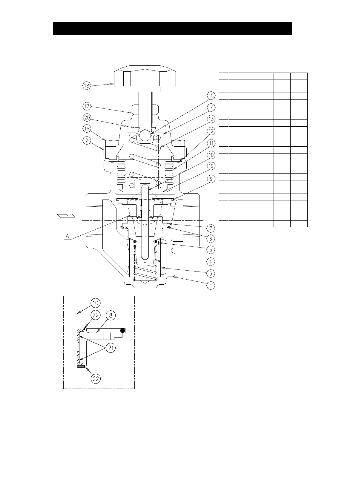
Configuration.....................................................................5
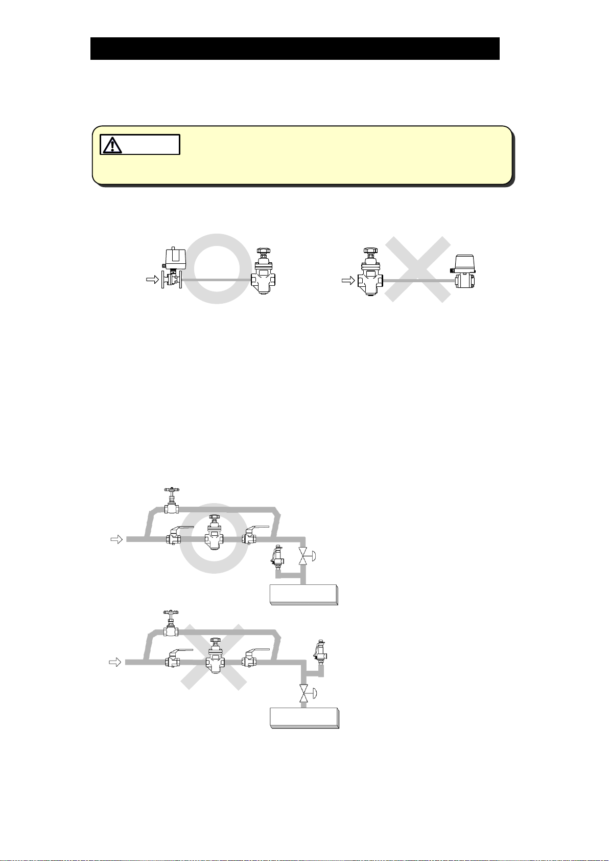
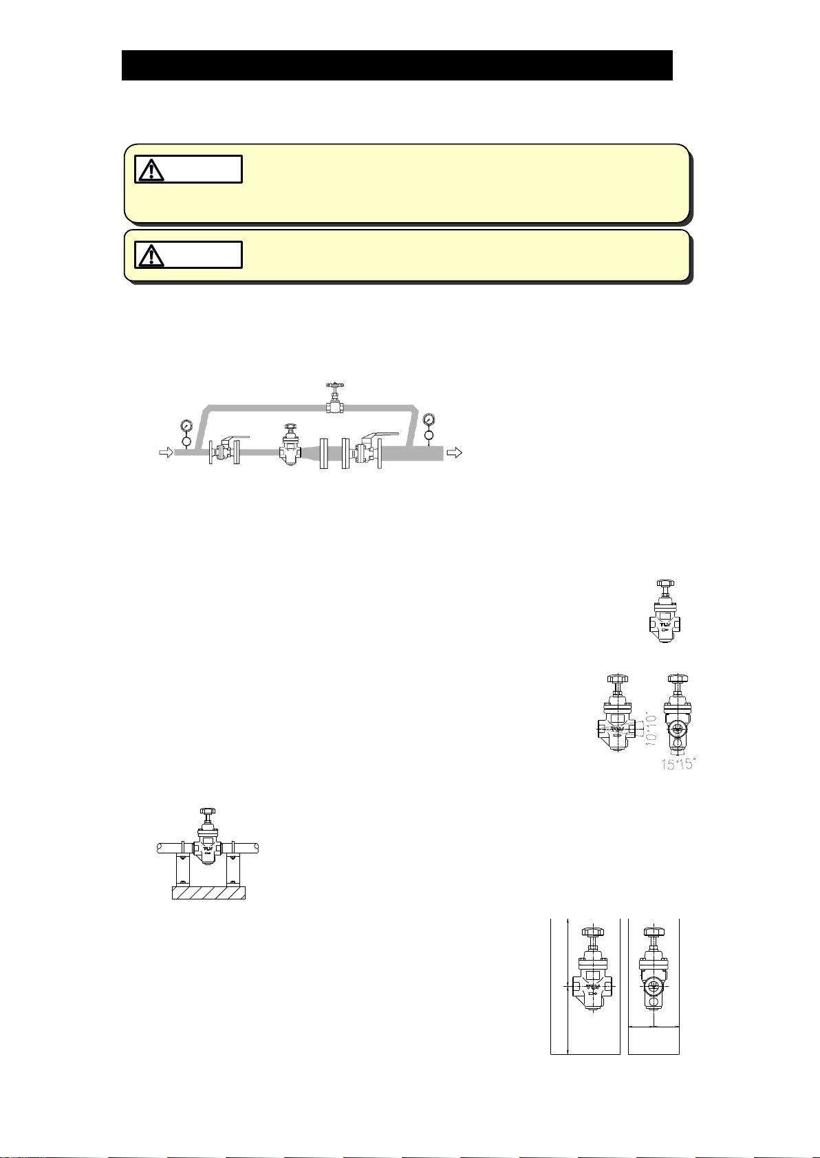
Correct Usage of the A-DR20 Direct-acting Pressure
Reducing Valve.................................................................6
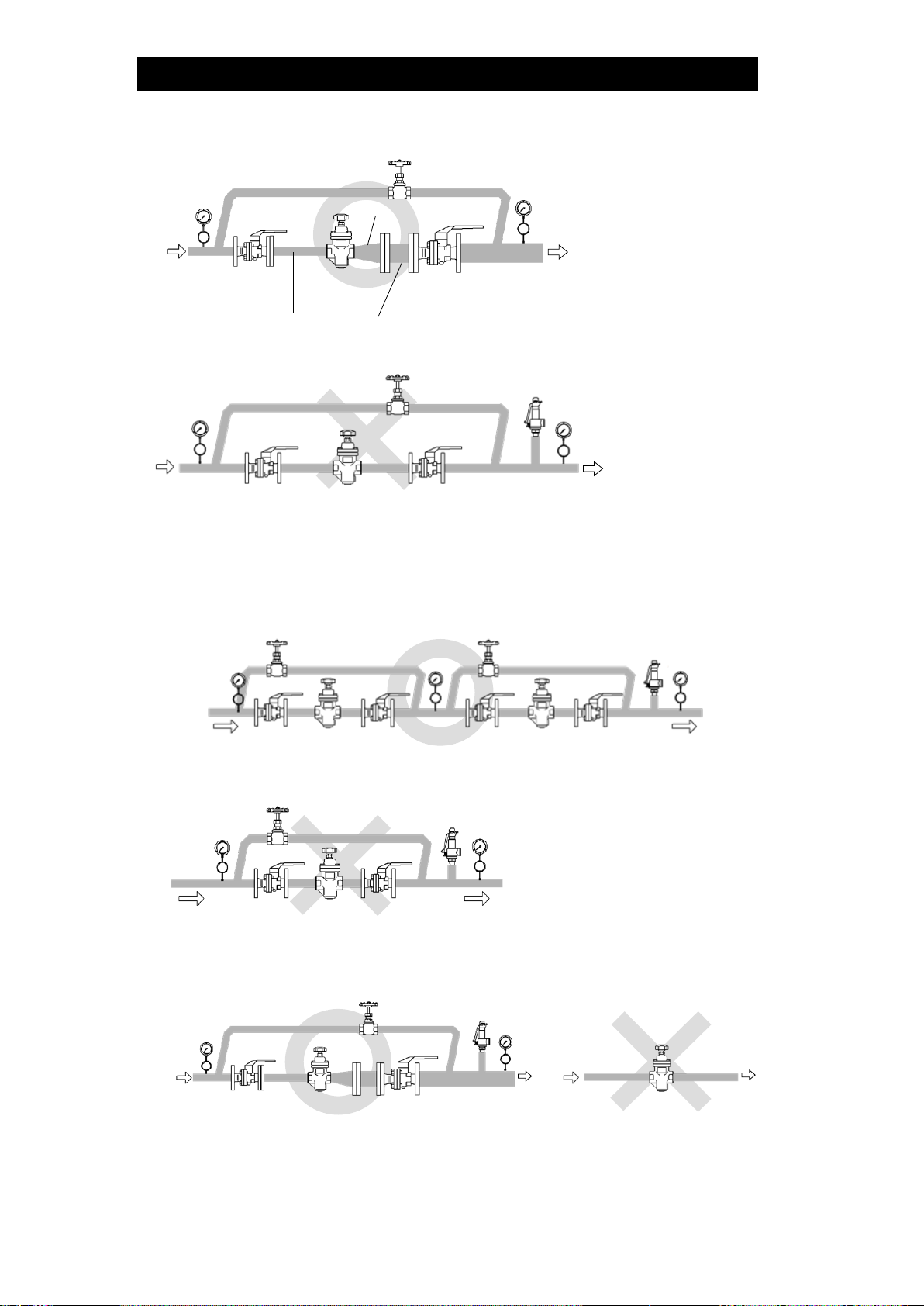
Installation.........................................................................8
Adjustment ......................................................................10
Maintenance....................................................................10
Disassembly....................................................................11
Reassembly ....................................................................14
Troubleshooting ..............................................................15
TLV EXPRESS LIMITED WARRANTY...........................17
Service............................................................................19
Introduction
Thank you for purchasing the TLV A-DR20 direct-acting pressure reducing
valve for air.
This product has been thoroughly inspected before being shipped from the
factory. When the product is delivered, before doing anything else, check the
specifications and external appearance to make sure nothing is out of the
ordinary. Also be sure to read this manual carefully before use and follow the
instructions to be sure of using the product properly.
The TLV A-DR20 is a direct-acting pressure reducing valve for air which
adopts a soft seat design on the main valve and minimizes the lockup
pressure*. It also provides a more stable secondary pressure than
conventional direct-acting reducing valves. The A-DR20 is designed for a long
service life, and is made of stainless steel for superior durability.
For products with special order specifications or options, if detailed
instructions for the special order specifications or options are not contained in
this manual, please contact TLV for full details.
This instruction manual is intended for use with the model(s) listed on the front
cover. It is necessary not only for installation but for subsequent maintenance,
disassembly/reassembly and troubleshooting. Please keep it in a safe place
for future reference.
*Lockup pressure: The increase in set pressure that occurs after air-using equipment is shut
down by closing the inlet valve to the equipment