TLV CT20 User manual

172-65742MA-01 (CT20/CT20D) 7 October 2021
Electro-Pneumatic Control Valve
CT20/CT20D
(for Valve Unit)
Copyright © 2021 by TLV CO., LTD.
All rights reserved

172-65742MA-01 (CT20/CT20D) 7 Oct 2021
2
Contents
Introduction .......................................................................2
Safety Considerations.......................................................3
Specifications....................................................................5
Configuration.....................................................................6
Installation.........................................................................8
Maintenance....................................................................10
Disassembly/Reassembly...............................................11
Troubleshooting...............................................................20
TLV EXPRESS LIMITED WARRANTY...........................21
Service............................................................................23
Introduction
Thank you for purchasing the TLV electro-pneumatic control valve CT20/CT20D.
This product has been thoroughly inspected before being shipped from the
factory. When the product is delivered, before doing anything else, check the
specifications and external appearance to make sure nothing is out of the
ordinary. Also be sure to read this manual carefully before use and follow the
instructions to be sure of using the product properly.
If detailed instructions for special order specifications or options not contained
in this manual are required, please contact TLV for full details.
This instruction manual is intended for use with the model(s) listed on the
front cover. It is needed not only for installation, but also for subsequent
maintenance, disassembly/reassembly and troubleshooting. Please keep it in
a safe place for future reference.
For details of the actuator and the electro-pneumatic digital positioner, refer to
the respective instruction manuals issued by the manufacturer.

172-65742MA-01 (CT20/CT20D) 7 Oct 2021
3
Safety Considerations
Read this section carefully before use and be sure to follow the instructions.
Installation, inspection, maintenance, repairs, disassembly, adjustment and valve
opening/closing should be carried out only by trained maintenance personnel.
The precautions listed in this manual are designed to ensure safety and prevent
equipment damage and personal injury. For situations that may occur as a result
of erroneous handling, three different types of cautionary items are used to
indicate the degree of urgency and the scale of potential damage and danger:
DANGER, WARNING and CAUTION.
The three types of cautionary items above are very important for safety: be sure
to observe all of them as they relate to installation, use, maintenance and repair.
Furthermore, TLV accepts no responsibility for any accidents or damage
occurring as a result of failure to observe these precautions.
Symbols
Indicates a DANGER, WARNING or CAUTION item.
Indicates an urgent situation which poses a threat of death or
serious injury
Indicates that there is a potential threat of death or serious injury
Indicates that there is a possibility of injury or equipment/product
damage
Install properly and DO NOT use this product outside the
recommended operating pressure, temperature and other
specification ranges.
Improper use may result in such hazards as damage to the
product or malfunctions that may lead to serious accidents. Local
regulations may restrict the use of this product to below the
conditions quoted.
Use hoisting equipment for heavy objects (weighing
approximately 20 kg (44 lb) or more).
Failure to do so may result in back strain or other injury if the
object should fall.
DO NOT use only the actuator eye bolt when hoisting or lifting
the assembled product.
Failure to observe this precaution may lead to product damage.
Take measures to prevent people from coming into direct
contact with product outlets.
Failure to do so may result in burns or other injury from the
discharge of fluids.
When disassembling or removing the product, wait until the
internal pressure equals atmospheric pressure and the
surface of the product has cooled to room temperature.
Disassembling or removing the product when it is hot or under
pressure may lead to discharge of fluids, causing burns, other
injuries or damage.
Continued on the next page
DANGER
WARNING
CAUTION
CAUTION

172-65742MA-01 (CT20/CT20D) 7 Oct 2021
4
Be sure to use only the recommended components when
repairing the product, and NEVER attempt to modify the
product in any way.
Failure to observe these precautions may result in damage to the
product and burns or other injury due to malfunction or the
discharge of fluids.
Do not use excessive force when connecting threaded pipes
to the product.
Over-tightening may cause breakage leading to fluid discharge,
which may cause burns or other injury.
Use only under conditions in which no freeze-up will occur.
Freezing may damage the product, leading to fluid discharge,
which may cause burns or other injury.
Use only under conditions in which no water hammer will
occur.
The impact of water hammer may damage the product, leading to
fluid discharge, which may cause burns or other injury.
Make sure the power supply is OFF before carrying out work
on the wiring or inspections involving disassembly.
If such work is carried out with the power on, there is a danger
that equipment may malfunction or electric shock may occur,
leading to injury or other accidents.
Make sure that wiring work requiring a special license is
carried out by qualified personnel.
If carried out by unqualified personnel, overheating or short
circuits leading to injury, fires, damage or other accidents may
occur.
When using this product, NEVER stand close to, or leave
tools anywhere near, moving parts, such as the shaft.
Contact with moving parts or objects becoming caught in moving
parts could lead to injury or damage or other accidents.
CAUTION

172-65742MA-01 (CT20/CT20D) 7 Oct 2021
5
Specifications
Install properly and DO NOT use this product outside the recommended
operating pressure, temperature and other specification ranges.
Improper use may result in such hazards as damage to the product or
malfunctions which may lead to serious accidents. Local regulations
may restrict the use of this product to below the conditions quoted.
CAUTION
Use only under conditions in which no freeze-up will occur. Freezing
may damage the product, leading to fluid discharge, which may cause
burns or other injury.
CAUTION
Refer to the product nameplate for detailed specifications.
Valve Section
Actuator Section
*Maximum allowable pressure (PMA) and maximum allowable temperature (TMA) are
PRESSURE SHELL DESIGN CONDITIONS, NOT OPERATING CONDITIONS.
**Valve No. is displayed for products with options. This item is omitted from the
nameplate when there are no options.
Model
NominalDiameter
Maximum Allowable*
Pressure*
Maximum Operating
Pressure
Maximum Allowable
Temperature (TMA)*
Maximum Operating
Temperature (TMO)
Valve No.**
Serial No.
Operating Direction
Model
NominalDiameter
Maximum Allowable
Pressure*
Maximum Operating
Pressure
Maximum Allowable
Temperature (TMA)*
Maximum Operating
Temperature (TMO)
Valve No.**
Serial No.
Spring Range Pressure supplied to
Positioner
Valve Material
Valve Characteristic
Stroke Cv Value

172-65742MA-01 (CT20/CT20D) 7 Oct 2021
6
Configuration
CT20
No.
Part
M*
R*
1
Body
2
Valve Bonnet
3
Stem Connector Nut
4
Locknut
5
Guide Bushing
6
Stuffing Box V-ring Packing
7
Stuffing Box Washer
8
Stuffing Box Spring
9
Valve Plug & Stem
10
Valve Bonnet Gasket
11
Bolt
12
Nut
13
Valve Seat
14
Nameplate (Valve Section: front / Actuator Section: back)
15
Travel Indicator Scale
16
Stem Bracket Clamps
17
Drain Plug
18
Actuator Stem
19
Fixing Nut
*Replacement parts are available only in the following kits:
M = Maintenance Kit
R = Repair Kit
Actuator Section
Positioner Section
Valve Section
Eye Bolt
Actuator area 700 cm2(1.08 in2) only

172-65742MA-01 (CT20/CT20D) 7 Oct 2021
7
CT20D (Option)
No.
Part
M*
R*
1
Body
2
Valve Bonnet
3
Stem Connector Nut
4
Locknut
5
Guide Bushing
6
Stuffing Box V-ring Packing
7
Stuffing Box Washer
8
Stuffing Box Spring
9
Valve Plug & Stem
10
Valve Bonnet Gasket
11
Valve Bonnet Bolt
12
Valve Bonnet Nut
13
Valve Seat
14
Nameplate (Valve Section: front / Actuator Section: back)
15
Travel Indicator Scale
16
Stem Bracket Clamps
17
Drain Plug
18
Actuator Stem
19
Fixing Nut
*Replacement parts are available only in the following kits:
M = Maintenance Kit
R = Repair Kit
Actuator Section
Positioner Section
Valve Section
Eye Bolt
Actuator area 700 cm2(1.08 in2)only

172-65742MA-01 (CT20/CT20D) 7 Oct 2021
8
Installation
Install properly and DO NOT use this product outside the recommended
operating pressure, temperature and other specification ranges.
Improper use may result in such hazards as damage to the product or
malfunctions which may lead to serious accidents. Local regulations
may restrict the use of this product to below the conditions quoted.
CAUTION
Use hoisting equipment for heavy objects (weighing approximately
20 kg (44 lb) or more). Failure to do so may result in back strain or other
injury if the object should fall.
CAUTION
DO NOT use only the actuator eye bolt when hoisting or lifting the
assembled product. Failure to observe this precaution may lead to
product damage.
CAUTION
Take measures to prevent people from coming into direct contact with
product outlets. Failure to do so may result in burns or other injury from
the discharge of fluids.
CAUTION
Do not use excessive force when connecting threaded pipes to the
product. Over-tightening may cause breakage leading to fluid
discharge, which may cause burns or other injury.
CAUTION
Installation, inspection, maintenance, repairs, disassembly and adjustment and valve
opening/closing should be carried out only by trained maintenance personnel.
Check to make sure that the piping where the product is to be installed is constructed
properly. If the piping is not correctly constructed, the valve may not perform optimally.
1. Blowdown
Before installing the product, be sure to blow down all piping thoroughly.
If this is not possible, perform a blowdown using the bypass valve.
Blowdown is especially important for newly installed piping or after the
system has been shut down for a long period of time.
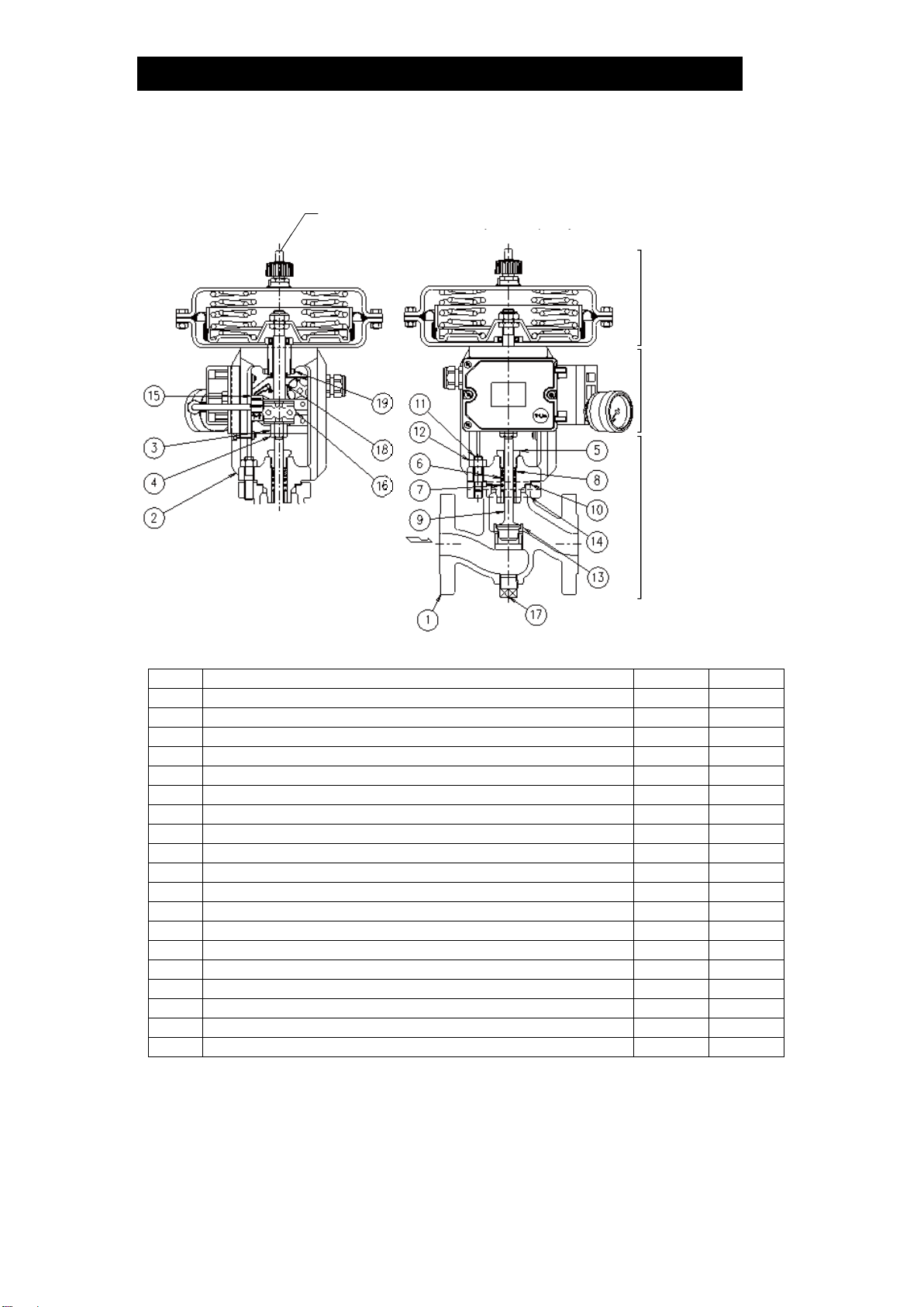
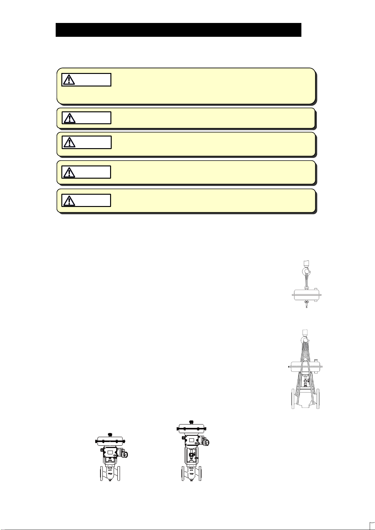
2. Installing the actuator section
The eye bolt welded onto the upper part of the diaphragm housing is
for mounting and removing the actuator. Do not lift the assembled
product using only the eye bolt.
(See Fig. 1)
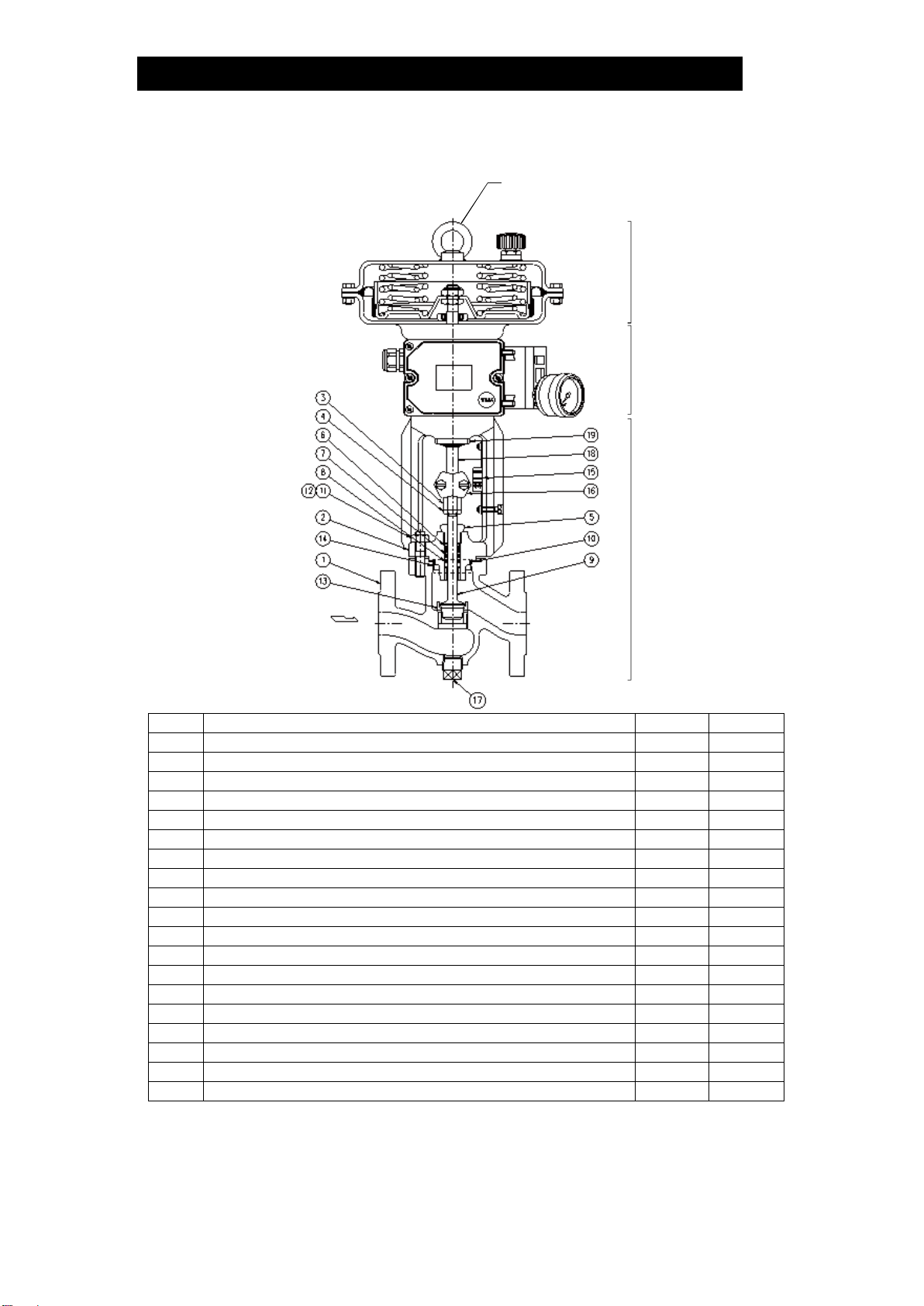
3. Installing the control valve
Lift the assembled product using hoisting equipment such as cranes
and forklifts. Do not lift the assembled product using only the eye bolt.
(See Fig. 2)
4. Removing protective caps and seals
Before installation, be sure to remove all protective seals and caps.
(Found in two locations, on the product inlet and outlet.)
CT20
CT20D
① ②
① ②
Fig. 1
Hoisting the
actuator
Fig. 2
Hoisting the
control valve

172-65742MA-01 (CT20/CT20D) 7 Oct 2021
9
5. Installation angle
Install the product so that the arrow mark on the valve
body points horizontally in the direction of steam flow, and
it should be installed horizontally in the piping with the
actuator at the top. Allowable inclination is 10 degrees in
the fore-aft direction and 15 degrees in the plane
perpendicular to the steam flow line.
6. Piping support
Install the product, paying attention to avoid excessive
load, bending and vibration. Support the inlet and outlet pipes securely.
CT20
CT20D
7. Maintenance space
Leave sufficient space for maintenance, inspection and repair. (Units: mm (in))
CT20
CT20D
8. Drainage port usage example
The threaded condensate drainage port at the
bottom of the body makes possible installation of a
blow valve or steam/air trap. Because the
condensate drainage port is located on the primary
side of the product, condensate flowing in the
primary side piping can quickly be eliminated,
contributing to prevention of valve seat erosion and
rapid start-up of the equipment.
If there is a problem in operation, determine the cause
using the “Troubleshooting” section in this manual.
300
(12)
400
(16)
400
(16)
400
(16)
400
(16)
300
(12)
100
(4)
100
(4)
100 (4)
100
(4)
100
(4)
100 to 190 (4 to 71/2)110 to 190 (41/2to 71/2)

172-65742MA-01 (CT20/CT20D) 7 Oct 2021
10
Maintenance
Take measures to prevent people from coming into direct contact with
product outlets. Failure to do so may result in burns or other injury from
the discharge of fluids.
CAUTION
When disassembling or removing the product, wait until the internal
pressure equals atmospheric pressure and the surface of the product
has cooled to room temperature. Disassembling or removing the
product when it is hot or under pressure may lead to discharge of fluids,
causing burns, other injuries or damage.
CAUTION
Be sure to use only the recommended components when repairing the
product, and NEVER attempt to modify the product in any way. Failure to
observe these precautions may result in damage to the product or burns
or other injury due to malfunction or the discharge of fluids.
CAUTION
Operational Check
An inspection of the following items should be done on a daily basis to determine
whether the product is operating properly or has failed. Periodically (at least
biannually) the operation should also be checked.
In the event of failure (malfunction), also refer to the "Troubleshooting" section for
remedies.
Inspection Item
Inspection Points
Remedy for Failure (Malfunction)
Leakage from valve
(when the valve is
closed)
Visual inspection or stethoscope
inspection; is the outlet side
pressure or temperature elevated,
or is there the sound of the
medium flowing?
Adjust the zero/span; if that does
not solve the problem, replace
with a new valve plug & stem
and valve seat
Leakage from gland
section
Visual inspection; is fluid leaking
from the gap between the guide
bushing and the valve stem, or
are there signs it has leaked
previously?
Coat the guide bushing and the
valve stem with grease; if that
does not solve the problem,
replace with new V-ring packing
Leakage from the
gaskets between
any pressurized
parts
Visual inspection; is fluid leaking
from the gasket areas on
pressurized parts?
Apply additional tightening (refer
to recommended torque) or
replace with new gaskets
Leakage from
pressurized parts
such as body and
valve bonnet
Visual inspection; is fluid leaking
from pressurized parts such as
the body or valve bonnet?
Replace any pressurized parts at
leak locations
Parts Inspection
When parts have been removed, use the following table to inspect the parts and
replace any that are found to be defective.
Inspection Item
Gasket(s): Check for warping and damage (Graphite gaskets MUST be replaced if disassembled)
Stuffing Box V-ring Packing: Check for warping or damage
Valve Plug & Stem, Valve Seat: Check for damage or scratches
Body, Valve Bonnet: Check for damages or corrosion

172-65742MA-01 (CT20/CT20D) 7 Oct 2021
11
Disassembly/Reassembly
When disassembling or removing the product, wait until the internal
pressure equals atmospheric pressure and the surface of the product
has cooled to room temperature. Disassembling or removing the
product when it is hot or under pressure may lead to discharge of fluids,
causing burns, other injuries or damage.
CAUTION
Be sure to use only the recommended components when repairing the
product, and NEVER attempt to modify the product in any way. Failure to
observe these precautions may result in damage to the product or burns
or other injury due to malfunction or the discharge of fluids.
CAUTION
Use the following procedures to remove components. Use the same procedures in
reverse to reassemble. (Installation, inspection, maintenance, repairs, disassembly,
adjustment and valve opening/closing should be carried out only by trained
maintenance personnel.)
For details of the actuator and the electro-pneumatic digital positioner, refer to the
respective instruction manuals issued by the manufacturer.
NOTE: Be sure to coat all threaded portions of the valve seat and bolts with anti-seize.
Removing/Reattaching the Actuator (Positioner)
Part
During Disassembly
During Reassembly
Stem Bracket Bolt
Loosen the stem bracket bolt and
remove the stem bracket clamps
connecting the actuator stem and
stem connector nut
Consult the table of tightening
torques and tighten to the proper
torque
―
When an input signal is sent to
the positioner, the actuator stem
will ascend
―
Fixing Nut
Remove the fixing nut connecting
the actuator and the valve bonnet
while keeping the actuator stem in
the raised position
Consult the table of tightening
torques and tighten to the proper
torque
Fixing Nut
Stem Bracket Clamps
Valve Bonnet

172-65742MA-01 (CT20/CT20D) 7 Oct 2021
12
Detaching/Reattaching the Stem Connector Nut and Locknut
Part
During Disassembly
During Reassembly
Locknut,
Stem Connector
Nut
Loosen the locknut by holding the
stem connector nut with a
spanner
DO NOT disassemble with the
valve plug in contact with the valve
seat, make sure that the valve plug
is slightly suspended
Do not supply air to the actuator at
a pressure of 0.6 MPaG (85 psig, 6
barg) or more.
Consult the table of tightening
torques and tighten to the proper
torque
If the instructions given are not
followed when reassembly is
carried out, malfunctions such as
insufficient lift (insufficient flow
capacity) and/or insufficient closing
force (valve leakage) may result:
give the proper attention to the
adjustment procedure
Stem Connector Nut
Locknut

172-65742MA-01 (CT20/CT20D) 7 Oct 2021
13
Instructions for Reverse Action (Air to Open, Fail Closed) Stroke Adjustment
1. Make sure that the valve plug is securely seated in the valve seat. (Fig. 1)
2. Supply the maximum air pressure (0.33 MPaG (48 psig, 3.3 barg)) of the spring
range (e.g. 0.09 to 0.33 MPaG (13 to 48 psig, 0.9 to 3.3 barg)) to the actuator.
(Refer to the nameplate, drawing or specification data sheet (SDS) for the spring
range.)
With the actuator stem raised, screw the locknut and stem connector nut into the
guide bushing as far as possible without touching the valve stem. (Fig. 2)
3. Supply the lower limit air pressure (0.09 MPaG (13 psig, 0.9 barg)) of the spring
range (e.g. 0.09 to 0.33 MPaG (13 to 48 psig, 0.9 to 3.3 barg)) to the actuator.
The actuator stem will descend. (Fig. 3)
NOTE: Be careful not to pinch your fingers.
4. Turn the stem connector nut until it comes into contact with the actuator stem,
and turn the stem connector nut a further 1/4 turn to contact the actuator stem.
Make sure that the valve plug is seated in the valve seat.
Hold the stem connector nut with a spanner and tighten the locknut with a
proper torque. (Fig. 4)
5. Shut off the air supply to the actuator.
NOTE: Be careful not to pinch your fingers.
6. Secure the stem connector nut and the actuator stem with the stem bracket
clamps. Make sure to adjust the stem bracket clamps to 0% (fully closed) on the
travel indicator scale. (Fig. 5)
Fig. 1
Fig. 2
Fig. 3
Fig. 4
Fig. 5
Actuator Stem
Valve Stem
Locknut
Stem
Connector Nut
Actuator Stem
ascends
Actuator Stem
descends
NOTE:
Be careful
not to pinch
your fingers
Stem
Connector Nut
Locknut
Stem Bracket Clamps Travel Indicator Scale
Travel Indicator Scale
Mounting Bolt
Travel Indicator Scale
Mounting Bolt

172-65742MA-01 (CT20/CT20D) 7 Oct 2021
14
Instructions for Direct Action (Air to Close, Fail Open) Stroke Adjustment
1.Make sure that the valve plug is securely seated in the valve seat. (Fig. 1)
2. Screw the locknut and coupling nut onto the valve stem until they are just short
of coming into contact with the guide bushing. (Fig. 2)
3. Supply the upper limit air pressure (0.1 MPaG (15 psig, 1.0 barg)) of the spring
range (e.g. 0.02 to 0.1 MPaG (3 to 15 psig, 0.2 to 1.0 barg)) to the actuator. The
actuator stem will descend. (Fig. 3)
NOTE: Be careful not to pinch your fingers.
4. Turn the stem connector nut until it comes into contact with the actuator stem,
and turn the stem connector nut a further 1/4 turn to contact the actuator stem.
Make sure that the valve plug is seated in the valve seat. Hold the stem
connector nut securely in place with a tool such as a spanner and tighten the
locknut. (Fig. 4)
5. Shut off the air supply to the actuator.
NOTE: Be careful not to pinch your fingers.
6. Secure the stem connector nut and the actuator stem with the stem bracket
clamps. Make sure to adjust the stem bracket clamps to 100% (fully open) on
the travel indicator scale. (Fig. 5)
Fig. 1
Fig. 2
Fig. 3
Fig. 4
Fig. 5
Actuator Stem
Valve Stem
Locknut
Stem
Connector Nut
Actuator Stem
ascends
Actuator Stem
descends
NOTE:
Be careful
not to pinch
your fingers
Actuator Stem
ascends
Pull up the stem
connector nut and
the valve stem
Stem Bracket
Clamps Travel Indicator Scale
Travel Indicator Scale
Mounting Bolt
Travel Indicator Scale
Mounting Bolt

172-65742MA-01 (CT20/CT20D) 7 Oct 2021
15
Disassembling/Reassembling the Gland and its Components
In the procedure below, first partially loosen the guide bushing and then remove the
valve plug & stem before removing the other parts. (The procedure is most easily
performed if the bushing is loosened while it is attached to the valve body.)
Part
During Disassembly
During Reassembly
Guide Bushing
Remove with a
socket wrench
Consult the table of tightening torques and
tighten to the proper torque
Stuffing Box V-ring
Packing
Pull up and out
Make sure to reassemble the V-ring packing
in the proper orientation; coat the groove with
heat-resistant silicon grease; reattach the V-
ring packing with the grooves facing
downward
Stuffing Box Washer/
Stuffing Box Spring
Pull up and out
Reinsert
Guide Bushing
Stuffing Box V-ring Packing
Stuffing Box Washer
Stuffing Box Spring
Cut view of
Stuffing Box
V-ring Packing

172-65742MA-01 (CT20/CT20D) 7 Oct 2021
16
Disassembling/Reassembling of the Valve Bonnet Section
Part
During Disassembly
During Reassembly
Nut
Remove with a socket
wrench
Consult the table of tightening torques and
tighten to the proper torque, making sure to
tighten evenly
Valve Bonnet
Pull up and off, being
careful not to damage the
valve plug or valve seat
Reattach, being careful not to damage the
valve plug or valve seat; insert the bonnet
securely into the gasket housing without tilting;
check to make sure that there is no catching or
biting when the valve plug is seated in the
valve seat, and that the valve plug is securely
seated in the valve seat
Valve Bonnet
Gasket
Remove the gasket and
clean sealing surfaces
Replace with a new gasket; make sure that the
gasket does not protrude from the housing in
the body; DO NOT coat with anti-seize
Nut
Valve Bonnet
Gasket
Valve Plug
Valve Bonnet
Section
Body Section

172-65742MA-01 (CT20/CT20D) 7 Oct 2021
17
Disassembling/Reassembling the Valve Plug & Stem
After pulling out the valve plug, remove the loosened guide bushing, stuffing box V-
ring packing, washer and coil spring.
Part
During Disassembly
During Reassembly
Valve Plug &
Stem
-
When the Cv value is 30 or
greater, be careful of the
orientation of the valve
wing-blades during
reassembly; improper
orientation can result in
noise or erosion of the valve
plug and/or valve seat
NOTE: Valve reassembly orientation for Cv values of 30 or greater.
(When the Cv value is 20 or less, there is no designated
reassembly orientation.)
Cv Value:
20 or less
Cv Value:
30 or more
Valve Plug: Viewed from side
Valve Plug: Viewed from bottom
Removing/Reinserting the Valve Seat (Special tool required)
Part
During Disassembly
During Reassembly
Valve Seat
This procedure requires a special
tool; contact TLV for details
Over-tightening could result in
damage to the valve seat and body;
consult the table of tightening
torques and tighten to the proper
torque
Shallow
cut-away
Shallow
cut-away
Shallow
cut-away
Deep cut-away
outlet
Direction of
inlet flow
Valve: viewed from side Valve: viewed from bottom
Direction of
inlet flow
Valve Seat

172-65742MA-01 (CT20/CT20D) 7 Oct 2021
18
Table of Tightening Torques
Part
Size
Torque
Distance Across Flats
mm
(in)
N·m
(lbf·ft)
mm
(in)
Guide Bushing
15 to 80
(1/2to 3)
50
(37)
24
(15/16)
100, 150
(4, 6)
80
(59)
27
(11/16)
Valve Bonnet Nut
15 to 25
(1/2to 1)
30
(22)
16/171)
(5/8/ 21/32)1)
40, 50
(11/2, 2)
50
(37)
18/191)
(11/16 / 3/4)1)
65, 80
(21/2, 3)
100
(73)
24
(15/16)
100, 150
(4, 6)
150
(110)
30
(13/16)
Valve Seat
15 to 25
(1/2to 1)
170
(124)
Special tool required 2)
40, 50
(11/2, 2)
500
(368)
65, 80
(21/2, 3)
1050
(774)
100
(4)
1550
(1143)
150
(6)
2600
(1918)
Fixing Nut
15 to 150
(1/2to 6)
150
(110)
Special tool required2)
Stem Connector
Nut, Locknut
15 to 80
(1/2to 3)
50
(37)
16/171)
(5/8/ 21/32)1)
100, 150
(4, 6)
120
(88)
24
(15/16)
Stem Bracket
Bolt
240 cm2 3)
(0.37 in2)3)
5
(4)
8
(5/16)
350 cm2 3)
(0.54 in2)3)
9
(6.5)
9
(11/32)
700 cm2 3)
(1.08 in2)3)
9
(6.5)
9
(11/32)
Drain Plug4)
15 to 150
(1/2to 6)
50
(37)
1) Size depends on bolt specifications. (1 Nm 10 kgcm)
2) Contact TLV for details.
3) Actuator area
4) Rc(PT)1/2, other standards available. Torque values with sealing tape wrapped 3 to 3.5
turns around the threads
NOTE:
-Coat all threaded portions with anti-seize.
-If drawings or other special documentation were supplied for the product, any torque
given there takes precedence over values shown here.

172-65742MA-01 (CT20/CT20D) 7 Oct 2021
19
Exploded View
Guide Bushing
Stuffing Box V-ring Packing
Stuffing Box Washer
Stuffing Box Spring
Nut
Drain Plug
Body
Valve Bonnet Gasket
Valve Seat
Bolt
Locknut
Stem Connector Nut
Travel Indicator Scale
Valve Bonnet
Front: Model, size, date of manufacture
Back: Spring range, Cv value, etc.
Nameplate (The shape of the plug
differs depend on the size
and the Cv value)
Valve Plug & Stem
(A special tool is required
for disassembly/
reassembly)

172-65742MA-01 (CT20/CT20D) 7 Oct 2021
20
Troubleshooting
When disassembling or removing the product, wait until the internal
pressure equals atmospheric pressure and the surface of the product
has cooled to room temperature. Disassembling or removing the
product when it is hot or under pressure may lead to discharge of fluids,
causing burns, other injuries or damage.
CAUTION
When the valve unit fails to operate properly, use the following table to locate the
cause and remedy. When the actuator and positioner fail to operate properly, refer
to the applicable manual.
Problem
Cause
Diagnosis
Remedy (Countermeasure)
Valve Leakage
The pressure of the air
supply to the positioner
is too high
Check the pressure of
the air supply to the
positioner
(confirm product
specifications on the
nameplate)
Adjust the pressure of the
air supply for the positioner
to match the pressure in the
product specifications
Refer to the instruction
manual for the positioner
for zero point adjustment
The positioner’s zero
point is miscalibrated
Check the actuator air
supply pressure (on
the positioner’s
pressure gauge) when
the operation signal is
at zero point
If the pressure on the
pressure gauge is elevated,
adjust the positioner’s zero
point (refer to the instruction
manual for positioner)
The inlet pressure for
the control valve is too
high
Check the inlet
pressure for the control
valve
Decrease the inlet pressure
(Cv value and the spring
range must be changed)
The valve plug and
valve seat are off-
center
Move the valve plug &
stem up and down and
check to see if it
catches
Reassemble the valve
bonnet section correctly
Wear of the sealing
surfaces of the valve
plug and valve seat
Check the valve plug
and valve seat
Replace the valve plug and
valve seat.
Consider replacing with a
valve plug and valve seat of
a more durable material.
This manual suits for next models
1
Table of contents
Other TLV Control Unit manuals
Popular Control Unit manuals by other brands

Cobalt Digital Inc
Cobalt Digital Inc BBG-1040-ACO product manual

Graco
Graco Pro-Shot A Series instructions

Elsner
Elsner AQS/TH PF Installation and adjustment manual

NI
NI TBX-68 user guide

Skov
Skov BlueControl Insect Technical user guide

Chicony Electronics
Chicony Electronics W704D0-A1 Quick installation guide

Festo
Festo VSNZ-FT-T32C-M F-P1-T6 Series Assembly instructions

FlexRadio
FlexRadio FLEX-6000 Signature Series user guide

Johnson Controls
Johnson Controls UL Listed GS-20 Series manual

Reflex
Reflex fillset Installation, operating and maintenance instructions

Pickering
Pickering 40-296 user manual

ROBBE-Futaba
ROBBE-Futaba FX-32 instruction manual