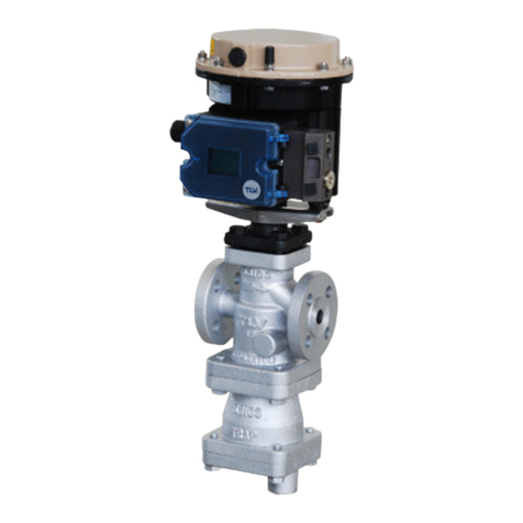
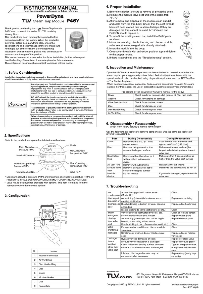
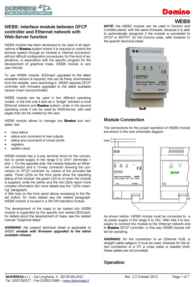
TLV MB12A User manual

172-65316M-08 (MB12A/MB12AF/MB12B/MB12BF) 7 October 2021
Motorized Ball Butterfly Valve
MB12A/MB12AF
MB12B/MB12BF
Copyright © 2021 by TLV CO., LTD.
All rights reserved

172-65316M-08 (MB12A/MB12AF/MB12B/MB12BF) 7 Oct 2021
1
Contents
Introduction ....................................................................... 1
Safety Considerations ....................................................... 2
Specifications .................................................................... 4
Configuration..................................................................... 6
Installation ......................................................................... 8
Manual Operation............................................................ 15
Maintenance.................................................................... 16
Disassembly/Reassembly ............................................... 18
Troubleshooting .............................................................. 22
TLV EXPRESS LIMITED WARRANTY........................... 24
Service ............................................................................ 26
Introduction
Thank you for purchasing the TLV motorized ball butterfly valve.
This product has been thoroughly inspected before being shipped from the
factory. When the product is delivered, before doing anything else, check the
specifications and external appearance to make sure nothing is out of the
ordinary. Also be sure to read this manual carefully before use and follow the
instructions to be sure of using the product properly.
The TLV motorized ball butterfly valve incorporates a ball butterfly valve,
which offers a combination of the superior sealing properties of the ball valve
and the smooth rotary movement of the butterfly valve, with an electric
actuator.
If detailed instructions for special order specifications or options not contained
in this manual are required, please contact TLV for full details.
This instruction manual is intended for use with the model(s) listed on the front
cover. It is necessary not only for installation, but for subsequent
maintenance, disassembly/reassembly and troubleshooting. Please keep it in
a safe place for future reference.

172-65316M-08 (MB12A/MB12AF/MB12B/MB12BF) 7 Oct 2021
2
Safety Considerations
•Read this section carefully before use and be sure to follow the instructions.
•Installation, inspection, maintenance, repairs, disassembly, adjustment and valve
opening/closing should be carried out only by trained maintenance personnel.
•The precautions listed in this manual are designed to ensure safety and prevent
equipment damage and personal injury. For situations that may occur as a result
of erroneous handling, three different types of cautionary items are used to
indicate the degree of urgency and the scale of potential damage and danger:
DANGER, WARNING and CAUTION.
•The three types of cautionary items above are very important for safety: be sure
to observe all of them as they relate to installation, use, maintenance and repair.
Furthermore, TLV accepts no responsibility for any accidents or damage
occurring as a result of failure to observe these precautions.
Symbols
Indicates a DANGER, WARNING or CAUTION item.
Indicates an urgent situation which poses a threat of death or
serious injury
Indicates that there is a potential threat of death or serious injury
Indicates that there is a possibility of injury or equipment/product
damage
DO NOT use for toxic, flammable or otherwise hazardous
fluids.
Use only for fluids listed in the specification table. This product is
for intended use only. Improper use may result in such hazards
as damage to the product or malfunctions that may lead to
serious accidents.
Install properly and DO NOT use this product outside the
recommended operating pressure, temperature and other
specification ranges.
Improper use may result in such hazards as damage to the
product or malfunctions that may lead to serious accidents. Local
regulations may restrict the use of this product to below the
conditions quoted.
Take measures to prevent people from coming into direct
contact with product outlets.
Failure to do so may result in burns or other injury from the
discharge of fluids.
When disassembling or removing the product, wait until the
internal pressure equals atmospheric pressure and the
surface of the product has cooled to room temperature.
Disassembling or removing the product when it is hot or under
pressure may lead to discharge of fluids, causing burns, other
injuries or damage.
Continued on the next page
DANGER
WARNING
CAUTION
WARNING
CAUTION

172-65316M-08 (MB12A/MB12AF/MB12B/MB12BF) 7 Oct 2021
3
Be sure to use only the recommended components when
repairing the product, and NEVER attempt to modify the
product in any way.
Failure to observe these precautions may result in damage to the
product and burns or other injury due to malfunction or the
discharge of fluids.
Do not use excessive force when connecting threaded pipes
to the product.
Over-tightening may cause breakage leading to fluid discharge,
which may cause burns or other injury.
Use only under conditions in which no freeze-up will occur.
Freezing may damage the product, leading to fluid discharge,
which may cause burns or other injury.
Make sure the power supply is OFF before carrying out work
on the wiring or inspections involving disassembly.
If such work is carried out with the power on, there is a danger
that equipment may malfunction or electric shock may occur,
leading to injury or other accidents.
Make sure that wiring work requiring a special license is
carried out only by qualified personnel.
If carried out by unqualified personnel, overheating or short circuits
leading to injury, fires, damage or other accidents may occur.
When using this product, be sure NEVER to stand close to, or
leave tools anywhere near, moving parts such as a shaft.
Contact with moving parts or objects becoming caught in moving
parts could lead to injury, damage or other accidents.
Use only under conditions in which no water hammer will
occur.
The impact of water hammer may damage the product, leading to
fluid discharge, which may cause burns or other injury.
CAUTION

172-65316M-08 (MB12A/MB12AF/MB12B/MB12BF) 7 Oct 2021
4
Specifications
DO NOT use for toxic, flammable or otherwise hazardous fluids.
Use only for fluids listed in the specification table. This product is for
intended use only. Improper use may result in such hazards as damage
to the product or malfunctions that may lead to serious accidents.
WARNING
Install properly and DO NOT use this product outside the recommended
operating pressure, temperature and other specification ranges.
Improper use may result in such hazards as damage to the product or
malfunctions which may lead to serious accidents. Local regulations
may restrict the use of this product to below the conditions quoted.
CAUTION
Use only under conditions in which no freeze-up will occur. Freezing
may damage the product, leading to fluid discharge, which may cause
burns or other injury.
CAUTION
Model
MB12A
MB12AF
MB12B
MB12BF
Connection
Screwed
Flanged
Screwed
Flanged
Max. Operating Press. PMO
1.0 MPaG
Max. Operating Temp. TMO
90 °C
185 °C
Max. Allowable Press. PMA*
1.0 MPaG
Max. Allowable Temp. PMO*
185 °C
Applicable Fluid
Cold water, hot water and air
Very hot water and steam
Cv Values
(Cv US)
Size
MB12A/ MB12B
MB12AF/MB12BF
15 mm
9.6
8.0
20 mm
18
16
25 mm
29
26
32 mm
50
47
40 mm
82
78
50 mm
135
135
Motor Type
Single-phase capacitor-run induction motor
Power Supply Voltage
100 V AC ±10%, 200 V AC ±10%
Electrical Consumption
Sizes 15 to 25 mm: 100 V: 50 V A, 200 V: 50 V A
Sizes 32 to 50 mm: 100 V: 69 V A, 200 V: 80 V A
Control System
Toggle switch for fully-open fully-closed
Overload Protection
Built-in thermal protector
Sizes 15 to 25 mm: 115 °C ±5 °C
Sizes 32 to 50 mm: 130 °C ±5 °C
Insulating Class
Class E
Direction of Rotation
Opening: Counter-clockwise (left) when viewed from above
Closing: Clockwise (right) when viewed from above
Open/Close Time
(for 90° rotation)
Sizes 15 to 25 mm: 50 Hz: 4.5 seconds
60 Hz: 4.0 seconds
Sizes 32 to 50 mm: 50 Hz: 5.5 seconds; 60 Hz: 4.5
seconds
Protection Class
IP54 equivalent (splash-proof model)
Manual Override
Possible when power supply is OFF
(1 MPa = 10.197 kg/cm2)
* Maximum allowable pressure (PMA) and maximum allowable temperature (TMA) are PRESSURE
SHELL DESIGN CONDITIONS, NOT OPERATING CONDITIONS
Avoid using the ball valve in the half-open position, as it may result in damage to the valve
seat. Be sure to use only in the fully open and fully closed positions.
Also, do not use with slurries.

172-65316M-08 (MB12A/MB12AF/MB12B/MB12BF) 7 Oct 2021
5
To prevent overheating of the motor unit, determine the minimum operation cycle
interval based on the ambient temperature from the graph below.
Ambient
Temperature Range
and Operation
Cycles
Ambient Temperature* (°C)
* Within one cm of cover
Operation cycle: The time for one cycle of opening and closing the
valve
A: Time to cycle from closed to open
B: Time to cycle from open to closed
Example:
When the ambient temperature is 40 °C and the medium in use is
steam, allow for an operation cycle interval of at least 36 seconds.
When the operation cycle interval is less than this, the thermal
protector may operate, causing operation to cease until the motor
temperature has fallen.
Specifications for No-voltage Contact Microswitch
Standard Model
Manufacturer
OMRON CORPORATION
Model
V-105-1A5-T
Contact Capacity
(Resistance Load)
15 to 250 V AC, 160 mA to 10 A
15 to 30 V DC, 160 mA to 6 A
15 to 125 V DC, 160 to 600 mA
Small-load Model
Manufacturer
Yamatake Corporation
Model
V-3214EK-011
Contact Capacity
(Resistance Load)
5 to 125 V AC, 5 to 100 mA
5 to 30 V DC, 5 to 100 mA
Operation Cycle
1.0 MPaG of Steam at 185 °C
Air at 20 °C
Operation Cycle (s)

172-65316M-08 (MB12A/MB12AF/MB12B/MB12BF) 7 Oct 2021
6
Configuration
Screwed
Flanged
Actuator Unit
Nameplate
Terminal Block
Mount Screw: M3
Connection
Diagram
Wiring Port
G½
Manual Open/Close
Shaft
(12 mm wide)
Valve Unit

172-65316M-08 (MB12A/MB12AF/MB12B/MB12BF) 7 Oct 2021
7
Valve Unit
Screwed
Flanged
No.
Name
1
Body
2S
Union
2F
Flange
3
Ball
4*
Valve Seat
5*
Washer
6*
Belleville Washer
7*
Valve Seat O-ring
8
Bushing
9
Body Gasket
10
Valve Shaft
11
Spindle
12
Holder
13
Washer
14
Belleville Washer
15
Gland Seat
16
Holder Gasket
17
Stem Packing
18
Seal
19
Guide Bushing
20
Holder Screw
21
Flange Bolt
*Inlet and outlet sides – 2 pieces

172-65316M-08 (MB12A/MB12AF/MB12B/MB12BF) 7 Oct 2021
8
Installation
DO NOT use for toxic, flammable or otherwise hazardous fluids.
Use only for fluids listed in the specification table. This product is for
intended use only. Improper use may result in such hazards as damage
to the product or malfunctions that may lead to serious accidents.
WARNING
Install properly and DO NOT use this product outside the recommended
operating pressure, temperature and other specification ranges.
Improper use may result in such hazards as damage to the product or
malfunctions which may lead to serious accidents. Local regulations
may restrict the use of this product to below the conditions quoted.
CAUTION
Take measures to prevent people from coming into direct contact with
product outlets. Failure to do so may result in burns or other injury from
the discharge of fluids.
CAUTION
Do not use excessive force when connecting threaded pipes to the
product. Over-tightening may cause breakage leading to fluid
discharge, which may cause burns or other injury.
CAUTION
Use only under conditions in which no freeze-up will occur. Freezing
may damage the product, leading to fluid discharge, which may cause
burns or other injury.
CAUTION
Make sure the power supply is OFF before carrying out work on the
wiring or inspections involving disassembly. If such work is carried out
with the power on, there is a danger that equipment may malfunction or
electric shock may occur, leading to injury or other accidents.
CAUTION
Make sure that wiring work requiring a special license is carried out only
by qualified personnel. If carried out by unqualified personnel,
overheating or short circuits leading to injury, fires, damage or other
accidents may occur.
CAUTION
When using this product, be sure NEVER to stand close to, or leave tools
anywhere near, moving parts such as a shaft. Contact with moving parts
or objects becoming caught in moving parts could lead to injury,
damage or other accidents.
CAUTION
Installation, inspection, maintenance, repairs, disassembly, adjustment and valve
opening/closing should be carried out only by trained maintenance personnel.
Installation Procedures
1. Before installation, be sure to remove all protective seals.
2. Before installing the product, thoroughly blow out the piping to
remove any piping scraps, dirt and oil.
3. When installing the product, confirm that sufficient maintenance
space has been secured around the product. Allow a space (H) of
at least 200 mm above the top of the product.
4. Where the product is installed in a location that may be affected
by radiant heat from nearby heat-generation, install a device such as a protective
plate to block the radiant heat.
5. There are no restrictions concerning which side is to be installed as the inlet and
which side is to be installed as the outlet.
6. Do not remove the cover except when necessary to carry out wiring, and do not
operate the product with the cover removed.
7. Use a connector, etc. for the wiring port (G½) to maintain the seal inside the cover.
8. For screwed models, the installation of unions at the inlet and outlet is
recommended to facilitate replacement of the valve unit.
If there is a problem, determine the cause by using the “Troubleshooting” section of
this manual.
H

172-65316M-08 (MB12A/MB12AF/MB12B/MB12BF) 7 Oct 2021
9
Wiring Procedures (Standard)
1. Connect the ON/OFF control switch as shown in the diagram below.
•When electricity flows through T1 and T3: As viewed from above, left rotation
for the valve fully open when stopped.
•When electricity flows through T2 and T3: As viewed from above, right rotation
for the valve fully closed when stopped.
2. Terminals 1, 2 and 3 can be wired for the ON/OFF pilot lamp.
•When the valve is fully open, the "O" pilot lamp is lit.
•When the valve is fully closed, the "C" pilot lamp is lit.
3. When checking the operation of the actuator unit before installing in the piping,
keep fingers well clear of the valve section.
4. Connect the electrical ground to the terminal block mounting screw on the
actuator unit.
Wiring Procedures (Standard + Optional Auxiliary Contact Model)
1. Connect the ON/OFF control switch as shown in the diagrams below.
•When electricity flows through T1 and T3: As viewed from above, left rotation
for the valve fully open when stopped.
•When electricity flows through T2 and T3: As viewed from above, right rotation
for the valve fully closed when stopped.
2. Auxiliary contact operation is shown below. The example below uses the pilot lamps.
Open: Lit when valve is fully open
Not Open: Lit when valve is not fully open
Closed: Lit when valve is fully closed
Not Closed: Lit when valve is not fully closed
3. When checking the operation of
the actuator unit before installing
in the piping, keep fingers well
clear of the valve section.
4. Connect the electrical ground to
the terminal block mounting
screw on the actuator unit.
NOTE: The auxiliary contact closed
signal is sent when the valve
reaches 5°before the fully
closed position. The auxiliary
contact opened signal is sent
when the valve reaches 5°
before the fully opened position.
Control Switch
AC
Power
Source
Internal Circuitry
Control Switch
AC
Power
Source
Internal Circuitry
AC/DC
Power
Source

172-65316M-08 (MB12A/MB12AF/MB12B/MB12BF) 7 Oct 2021
10
Wiring Procedures (Optional Relay Model (Energize to Open Type))
1. Connect the ON/OFF control switch as shown in the diagrams below.
•When the control switch is ON: As viewed from above, left rotation for the
valve fully open when stopped.
•When the control switch is OFF: As viewed from above, right rotation for the
valve fully closed when stopped.
2. Terminals 1, 2 and 3 can be wired for the ON/OFF pilot lamp.
•When the valve is fully open, the "O" pilot lamp is lit.
•When the valve is fully closed, the "C" pilot lamp is lit.
3. When checking the operation of the actuator unit before installing in the piping,
keep fingers well clear of the valve section.
4. Connect the electrical ground to the terminal block mounting screw on the
actuator unit.
NOTE: Excessively long controller wiring may lead to malfunction due to induction voltage. If
this occurs, install a relay near the motorized valve; use the relay contact for the
controller or install a resistor between terminals T1 and T3.
Contact TLV for details.
Control Switch
AC
Power
Source
Internal Circuitry

172-65316M-08 (MB12A/MB12AF/MB12B/MB12BF) 7 Oct 2021
11
Wiring Procedures (Optional Relay (Energize to Open Type) + Auxiliary
Contact Model)
1. Connect the ON/OFF control switch as shown in the following diagrams.
•When electricity flows through T1 and T3: As viewed from above, left rotation
for the valve fully open when stopped.
•When electricity flows through T2 and T3: As viewed from above, right rotation
for the valve fully closed when stopped.
2. Auxiliary contact operation is shown below.
The example below uses the pilot lamps.
Open: Lit when valve is fully open
Not Open: Lit when valve is not fully open
Closed: Lit when valve is fully closed
Not Closed: Lit when valve is not fully closed
3. When checking the operation of the actuator unit before installing in the piping,
keep fingers well clear of the valve section.
4. Connect the electrical ground to the terminal block mounting screw on the
actuator unit.
NOTE: • Excessively long controller wiring may lead to malfunction due to induction voltage.
If this occurs, install a relay near the motorized valve; use the relay contact for the
controller or install a resistor between terminals T1 and T3. Contact TLV for details.
• The auxiliary contact closed signal is sent when the valve reaches 5°before the
fully closed position. The auxiliary contact opened signal is sent when the valve
reaches 5°before the fully opened position.
Control Switch
AC
Power
Source
Internal Circuitry
AC/DC
Power
Source

172-65316M-08 (MB12A/MB12AF/MB12B/MB12BF) 7 Oct 2021
12
Wiring Procedures (Optional Relay Model (Energize to Close Type))
1. Connect the ON/OFF control switch as shown in the diagrams below.
•When the control switch is ON: As viewed from above, left rotation for the
valve fully closed when stopped.
•When the control switch is OFF: As viewed from above, right rotation for the
valve fully open when stopped.
2. Terminals 1, 2 and 3 can be wired for the ON/OFF pilot lamp.
•When the valve is fully open, the "O" pilot lamp is lit.
•When the valve is fully closed, the "C" pilot lamp is lit.
3. When checking the operation of the actuator unit before installing in the piping,
keep fingers well clear of the valve section.
4. Connect the electrical ground to the terminal block mounting screw on the
actuator unit.
NOTE: Excessively long controller wiring may lead to malfunction due to induction voltage. If
this occurs, install a relay near the motorized valve; use the relay contact for the
controller or install a resistor between terminals T1 and T3.
Contact TLV for details.
Control Switch
AC
Power
Source
Internal Circuitry

172-65316M-08 (MB12A/MB12AF/MB12B/MB12BF) 7 Oct 2021
13
Wiring Procedures (Optional Relay (Energize to Close Type) + Auxiliary
Contact Model)
1. Connect the ON/OFF control switch as shown in the following diagrams.
•When electricity flows through T1 and T3: As viewed from above, left rotation
for the valve fully closed when stopped.
•When electricity flows through T2 and T3: As viewed from above, right rotation
for the valve fully open when stopped.
2. Auxiliary contact operation is shown below.
The example below uses the pilot lamps.
Open: Lit when valve is fully open
Not Open: Lit when valve is not fully open
Closed: Lit when valve is fully closed
Not Closed: Lit when valve is not fully closed
3. When checking the operation of the actuator unit before installing in the piping,
keep fingers well clear of the valve section.
4. Connect the electrical ground to the terminal block mounting screw on the
actuator unit.
NOTE: • Excessively long controller wiring may lead to malfunction due to induction voltage.
If this occurs, install a relay near the motorized valve; use the relay contact for the
controller or install a resistor between terminals T1 and T3. Contact TLV for details.
• The auxiliary contact closed signal is sent when the valve reaches 5°before the
fully closed position. The auxiliary contact opened signal is sent when the valve
reaches 5°before the fully opened position.
Control Switch
AC
Power
Source
Internal Circuitry
AC/DC
Power
Source

172-65316M-08 (MB12A/MB12AF/MB12B/MB12BF) 7 Oct 2021
14
Wiring Procedures (Standard + Optional Space Heater Model)
Connect the space heater as shown in the diagrams below.
Temperature is controlled using a thermo-switch.
The diagram shows standard wiring with the space heater option. The options listed
below also have the H1 and H2 terminals and are wired in the same manner:
•Standard + Auxiliary Contact + Space Heater
•Relay + Space Heater
•Relay + Auxiliary Contact + Space Heater
Control Switch
AC
Power
Source
Internal Circuitry

172-65316M-08 (MB12A/MB12AF/MB12B/MB12BF) 7 Oct 2021
15
Manual Operation
Take measures to prevent people from coming into direct contact with
product outlets. Failure to do so may result in burns or other injury from
the discharge of fluids.
CAUTION
1. Perform manual operation only after first making sure that the power is OFF.
Manual operation is not possible when the power is ON.
For safety, make sure the power is OFF even during a power outage.
2. Using a wrench, turn the manual open/close shaft (side-to-side width: 12 mm)
located on the bottom (valve side) of the actuator.
Turn the shaft one revolution to rotate the valve section 90°.
The shaft may be turned in either direction.
There are no stoppers at the valve fully-open and fully-closed positions. Pay
close attention to the open/closed indicator as the shaft is being turned.
Manual
Open/Close
Shaft
Open/Closed
Indicator

172-65316M-08 (MB12A/MB12AF/MB12B/MB12BF) 7 Oct 2021
16
Maintenance
Take measures to prevent people from coming into direct contact with
product outlets. Failure to do so may result in burns or other injury from
the discharge of fluids.
CAUTION
Be sure to use only the recommended components when repairing the
product, and NEVER attempt to modify the product in any way. Failure to
observe these precautions may result in damage to the product or burns
or other injury due to malfunction or the discharge of fluids.
CAUTION
When using this product, be sure NEVER to stand close to, or leave tools
anywhere near, moving parts such as a shaft. Contact with moving parts
or objects becoming caught in moving parts could lead to injury,
damage or other accidents.
CAUTION
Operational Check of the Actuator Unit and Valve Unit
1. An operational check shall be performed at least once every 3 months.
2. Begin the supply of electricity to the actuator unit, and check the operation (angle
of rotation, time elapse for open/close, sound).
3. After shutting off the supply of electricity to the actuator unit, manually operate the
valve and check for foreign matter in the valve and check that the torque for
opening and closing force (rotational torque) is as it should be.
To do this, refer to the table of rotational torques found below. If a torque exceeds
twice the value of that found in the table, it is an abnormal torque and an
inspection should be performed.
Size
(mm)
Rotational Torque (N∙m)
No Load
1.0 MPaG Load
15
0.8
1.1
20
1.1
2.0
25
2.9
4.9
32
3.6
6.6
40
10.0
15.1
50
12.0
19.0
(1 N∙m ≈10 kg∙cm)

172-65316M-08 (MB12A/MB12AF/MB12B/MB12BF) 7 Oct 2021
17
Additional Tightening of the Valve Unit Gland Section
It is possible to further tighten the gland section in the valve unit. When there is
leakage from the gasket or seal, tighten the gland section further using the following
instructions:
1. Detach the actuator unit.
2. Follow the steps given below to apply additional tightening:
1) Loosen the holder screw.
2) Screw the holder further in with a socket wrench.
3) Retighten the holder screw.
Cautions to observe when applying additional tightening:
•Do not tighten the holder completely the first time. Tighten the holder only as
much as necessary to stop leakage.
•If leakage continues even after the holder has been tightened, replace worn parts
(gland section or valve unit).
Valve
Connection Size
(mm)
Socket Distance
Across Flats
(mm)
15 to 25
17
32 to 50
27
Holder Screw
Holde
Allen Wrench
2 mm across flat
Socket

172-65316M-08 (MB12A/MB12AF/MB12B/MB12BF) 7 Oct 2021
18
Disassembly/Reassembly
When disassembling or removing the product, wait until the internal
pressure equals atmospheric pressure and the surface of the product
has cooled to room temperature. Disassembling or removing the
product when it is hot or under pressure may lead to discharge of fluids,
causing burns, other injuries or damage.
CAUTION
Be sure to use only the recommended components when repairing the
product, and NEVER attempt to modify the product in any way. Failure to
observe these precautions may result in damage to the product or burns
or other injury due to malfunction or the discharge of fluids.
CAUTION
Make sure the power supply is OFF before carrying out work on the
wiring or inspections involving disassembly. If such work is carried out
with the power on, there is a danger that equipment may malfunction or
electric shock may occur, leading to injury or other accidents.
CAUTION
Use the following procedures to remove components. Use the same procedures in
reverse to reassemble.
(Installation, inspection, maintenance, repairs, disassembly, adjustment and valve
opening/closing should be carried out only by trained maintenance personnel.)
Detaching/Reattaching the Actuator Unit and Valve Unit
Part
During Disassembly
During Reassembly
Part Inspection
Allen
Screw
Remove with an allen
wrench
Coat threads with anti-
seize and tighten to the
proper torque
—
Spring
Washer
Remove the spring
washer
Reinsert spring washer
—
Actuator
Unit
Slowly pull actuator unit
up and off
Remount the actuator
unit
—
Connector
Detach the connector
Reattach the connector
Check for deformation or
wear
Part: Allen Screw
Valve Size Torque
Distance
Across Flats
mm
N∙m
mm
15 to 25
10
5
32 to 50
12
6
(1 N∙m ≈10 kg∙cm)
Allen Wrench
Allen Screw
Spring Washer Connector
Valve Unit
Actuator Unit

172-65316M-08 (MB12A/MB12AF/MB12B/MB12BF) 7 Oct 2021
19
Disassembly/Reassembly of the Valve Unit Gland Section
Part
During Disassembly
During Reassembly
Part Inspection
Holder
Screw
Remove with an allen
wrench
If the valve body material is
stainless steel, coat threads with
anti-seize; tighten to the proper
torque
—
Holder
Remove with a socket
wrench
If the valve body material is
stainless steel, coat threads with
anti-seize; tighten to the proper
torque
—
Guide
Bushing
Remove the bushing
Reinsert the bushing
Check for wear
Seal
Remove the seal
Replace with a new seal
—
Stem
Packing
Remove the stem
packing
Replace with new stem packing —
Spindle
Remove the spindle
Reinsert the spindle – 2 flat
surfaces should fit into the slot in
the ball
Check the 2 flat
surfaces for
deformation,
wear, scratches,
corrosion, etc.
Valve Shaft
Remove the valve shaft
Reinsert the valve shaft
Check for wear,
deformation, etc.
Gland Seat
Remove the gland seat
Replace with a new gland seat with
the proper orientation
—
Washer
Remove the washer
Reinsert the washer
Check for
damage,
deformation, etc.
Belleville
Washer
Remove the Belleville
washer
Reinsert the Belleville washer with
the proper orientation
Check for
damage,
deformation, etc.
Holder
Gasket
Remove the gasket and
clean sealing surfaces
Replace with a new gasket if
damaged; be careful of the
orientation when inserting
—
Part
Valve
Size Torque
Distance
Across
Flats
mm
N∙m
mm
Holder
Screw 15 – 50 1.2 2
Holder
15 – 25
50
17
32 – 50
80
27
(1 N∙m ≈10 kg∙cm)
NOTE:
1. Reassemble the gland section only after
first reassembling the valve section.
2. To facilitate reinsertion of the spindle and
valve shaft into the ball, for the screwed
model first finger-tighten the inlet union,
for the flanged model first finger-tighten
the flange. This centers ball, thus making
it easier to reassemble. When
reassembly is completed, tighten the
valve holder.
Holder
Guide Bushing
Seal
Stem Packing
Spindle
Valve Shaft
Gland Seat
Washer
Belleville Washer
Holder Gasket
Holder Screw
This manual suits for next models
3
Table of contents
Other TLV Control Unit manuals
Popular Control Unit manuals by other brands
StorageTek
StorageTek 9714 Hardware operator's guide
MESI
MESI CUFFMD quick guide

Spirax Sarco
Spirax Sarco LCV6 Installation and maintenance instructions
Texas Instruments
Texas Instruments TPS54226EVM-539 user guide
Flowserve
Flowserve APS1 Installation, operation and maintenance instructions

Hioki
Hioki U8793 instruction manual
