TLV COSPECT PN-COS-16 User manual
172-65588MA-02 (PN-COS Pneumatic Control Valve) 5 September 2014 ISO 9001/ ISO 14001
Manufacturer
Kakogawa, Japan
is approved by LRQA LTD. to ISO 9001/14001
Pneumatic Control Valve for Steam
COSPECT
PN-COS-16
Copyright © 2014 by TLV CO., LTD.
All rights reserved

1
Contents
Introduction ........................................................................ 1
Safety Considerations ........................................................ 2
Specifications ..................................................................... 4
Acceptable Operating Range ............................................. 4
Correct Usage of the PN-COS-16...................................... 5
Configuration...................................................................... 7
Installation .......................................................................... 8
Operation ......................................................................... 14
Maintenance..................................................................... 17
Disassembly..................................................................... 18
Reassembly ..................................................................... 22
Troubleshooting ............................................................... 23
Product Warranty ............................................................. 26
Introduction
Thank you for purchasing the pneumatic control valve for steam, model PN-
COS-16.
This product has been thoroughly inspected before being shipped from the factory.
When the product is delivered, before doing anything else, check the specifications
and external appearance to make sure nothing is out of the ordinary. Also be sure to
read this manual carefully before use and follow the instructions to be sure of using
the product properly.
The pneumatic control valve for steam, model PN-COS-16 is a new type of
pneumatic control valve for steam that utilizes the structure of the COSPECT series
pilot operated pressure reducing valve, which is our unique product. Steam-using
equipment can achieve its intended efficiency only if the steam being used is very dry.
Using steam in which matter such as condensate, scale, types of grease or air is
entrained can not only result in problems with the steam-using equipment and in
lowered productivity, but can also lead to shortened service life for and malfunction of
the control valves.
The pneumatic control valve for steam, model PN-COS-16, has a built-in cyclone
separator, screen, and steam trap that eliminates these problems and makes possible
the supply of very dry steam at a stable pressure.
The PN-COS-16 can operate automatically and provide accurate pressure control and
temperature control when combined with the SC-F70 digital indicator controller or
a general-purpose controller. (However, for process temperature control, the desired
process temperature must be controllable by a secondary pressure within the adjustable
pressure range of the PN-COS-16.) Additionally, manual remote setting or 2 point
pressure switching as a pressure reducing valve is possible by combination with an air
regulator (with relief function).
If detailed instructions for special order specifications or options not contained in this
manual are required, please contact for full details.
This instruction manual is intended for use with the model(s) listed on the front cover.
It is needed not only for installation, but also for subsequent maintenance,
disassembly/reassembly and troubleshooting. Please keep it in a safe place for future
reference.
172-65588MA-02 (PN-COS Pneumatic Control Valve) 5 Sep 2014

2
Safety Considerations
Read this section carefully before use and be sure to follow the instructions.
Installation, inspection, maintenance, repairs, disassembly, adjustment and valve
opening/closing should be carried out only by trained maintenance personnel.
The precautions listed in this manual are designed to ensure safety and prevent
equipment damage and personal injury. For situations that may occur as a result
of erroneous handling, three different types of cautionary items are used to
indicate the degree of urgency and the scale of potential damage and danger:
DANGER, WARNING and CAUTION.
The three types of cautionary items above are very important for safety: be sure to
observe all of them as they relate to installation, use, maintenance and repair.
Furthermore, TLV accepts no responsibility for any accidents or damage occurring
as a result of failure to observe these precautions.
Symbols
Indicates a DANGER, WARNING or CAUTION item.
DANGE
R
Indicates an urgent situation which poses a threat of death or
serious injury
WARNING Indicates that there is a potential threat of death or serious injury
CAUTION
Indicates that there is a possibility of injury or equipment / product
damage
WARNING
NEVER apply direct heat to the float.
The float may explode due to increased internal pressure,
causing accidents leading to serious injury or damage to property
and equipment.
CAUTION
Install properly and DO NOT use this product outside the
recommended operating pressure, temperature and other
specification ranges.
Improper use may result in such hazards as damage to the
product or malfunctions that may lead to serious accidents. Local
regulations may restrict the use of this product to below the
conditions quoted.
DO NOT use the product in excess of the maximum
operating pressure differential.
Such use could make discharge through the steam trap
impossible (blocked).
Use hoisting equipment for heavy objects (weighing
approximately 20 kg (44 lb) or more).
Failure to do so may result in back strain or other injury if the
object should fall.
Take measures to prevent people from coming into direct
contact with product outlets.
Failure to do so may result in burns or other injury from the
discharge of fluids.
Safety considerations continued on the next page
172-65588MA-02 (PN-COS Pneumatic Control Valve) 5 Sep 2014

3
CAUTION When disassembling or removing the product, wait until the
internal pressure equals atmospheric pressure and the
surface of the product has cooled to room temperature.
Disassembling or removing the product when it is hot or under
pressure may lead to discharge of fluids, causing burns, other
injuries or damage.
Be sure to use only the recommended components when
repairing the product, and NEVER attempt to modify the
product in any way.
Failure to observe these precautions may result in damage to the
product and burns or other injury due to malfunction or the
discharge of fluids.
Do not use excessive force when connecting threaded pipes
to the product.
Over-tightening may cause breakage leading to fluid discharge,
which may cause burns or other injury.
Use only under conditions in which no freeze-up will occur.
Freezing may damage the product, leading to fluid discharge,
which may cause burns or other injury.
Use only under conditions in which no water hammer will
occur.
The impact of water hammer may damage the product, leading to
fluid discharge, which may cause burns or other injury.
Make sure the power supply is OFF before carrying out
work on the wiring or inspections involving disassembly.
If such work is carried out with the power on, there is a danger
that equipment may malfunction or electric shock may occur,
leading to injury or other accidents.
Make sure that wiring work requiring a special license is
carried out by qualified personnel.
If carried out by unqualified personnel, overheating or short circuits
leading to injury, fires, damage or other accidents may occur.
When using this product, NEVER stand close to, or leave
tools anywhere near moving parts, such as the shaft.
Contact with moving parts or objects becoming caught in moving
parts could lead to injury or damage or other accidents.
172-65588MA-02 (PN-COS Pneumatic Control Valve) 5 Sep 2014

4
Specifications
Install properly and DO NOT use this product outside the recommended
operating pressure, temperature and other specification ranges.
Improper use may result in such hazards as damage to the product or
malfunctions which may lead to serious accidents. Local regulations
may restrict the use of this product to below the conditions quoted.
CAUTION
DO NOT use the product in excess of the maximum operating pressure
differential; such use could make discharge through the steam trap
impossible (blocked).
CAUTION
Use only under conditions in which no freeze-up will occur. Freezing
may damage the product, leading to fluid discharge, which may cause
burns or other injury.
CAUTION
Refer to the product nameplate for detailed specifications.
Primary Pressure Range
Model
Serial Number
Nominal Diameter
Maximum Operating
Temperature
Valve No.*
Secondary Pressure
Adjustable Range
* Valve No. is displayed for products with options. This item is omitted from the nameplate
when there are no options.
<Required utilities>
Maximum Pressure 1.6 MPaG (250 psig)
Required Air Pressure [Desired secondary pressure + 0.1] MPaG
or higher
[Desired secondary pressure + 15] psig
or higher
Air Connecting Port Rc(PT), BSP or NPT 1/4"
Adjustment
Section
(Drive Section)
Motive
Air
Air Quality Oil-free air, filtered to 5 m
(1 MPa = 10.197 kg/cm2)
<CV Value>
Size: mm (in) 15 (1/2) 20 (3/4) 25 (1) 40 (11/2) 50 (2)
CV (US) 3.8 6.9 11.1 24.0 37.2
CV (UK) 3.2 5.7 9.2 20.0 31.0
Kvs (DIN) 3.3 5.9 9.5 20.6 31.9
Acceptable Operating Range
Model PN-COS-16
Primary Pressure Range* 0.2 –1.6 MPaG (30 – 250 psig)
Within 10 –84% of the primary pressure
(Minimum adjustable pressure of 0.03 MPaG (5 psig)
Adjustable Pressure Range
(All conditions must be met)
Pressure differential between 0.07 – 0.85 MPa (10 –120 psi)
Minimum Adjustable Flow Rate 5% of rated flow rate
(1 MPa = 10.197 kg/cm2)
*For process temperature control, the desired process temperature must be controllable by a
secondary pressure within the adjustable pressure range of the PN-COS-16.
172-65588MA-02 (PN-COS Pneumatic Control Valve) 5 Sep 2014
5
Correct Usage of the PN-COS-16
Install properly and DO NOT use this product outside the recommended
operating pressure, temperature and other specification ranges.
Improper use may result in such hazards as damage to the product or
malfunctions which may lead to serious accidents. Local regulations
may restrict the use of this product to below the conditions quoted.
CAUTION
1. The PN-COS-16 should be operated only within its specifications.
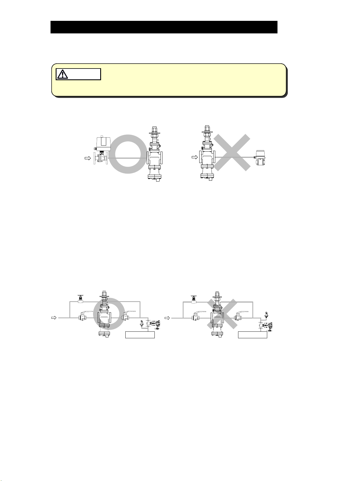
2. Installing an ON / OFF Valve (Solenoid Valve or Motorized Valve)
PN-COS
Motorized
Valve
Inlet side
PN-COS
Solenoid
Valve
Outlet side
If an on-off valve, such as a motorized valve, is required to stop supply of steam
to the steam-using equipment, install it at the inlet side of the PN-COS-16. If a
solenoid valve is installed at the outlet of the PN-COS-16, its opening and
closing will cause heavy chattering and may lead to damage of the piston and
main valve. (When the on-off valve opens, the secondary pressure of the PN-
COS-16 changes from zero to the set pressure. Passing through an area of the
reducing ratio of less than 10:1, where adjustment is impossible, chattering
occurs momentarily.) To save energy, it is recommended to install the on-off
valve as near to the boiler as possible.
NOTE: To prevent water hammer, it is recommended that a slow-acting motorized
on-off valve be used. In particular, if a fast-acting on-off solenoid valve is
used for frequent temperature control, the potential water hammer effect
can damage the steam-using equipment and the PN-COS-16.
3. Installing a Control Valve
Control
Valve
Equipment
PN-COS
Safety
Valve
Equipment
PN-COS
Safety
Valve
Control
Valve
A control valve installed between the PN-COS-16 and the steam-using equipment
(downstream of the PN-COS-16) for controlling equipment temperature may raise
the pressure between the PN-COS-16 and the control valve when the control
valve is closed, depending on the spatial relationship. A safety valve should be
installed downstream of the control valve.
NOTE: When installing a safety valve to protect the steam-using equipment, be sure
to install it on the steam-using equipment or directly before the inlet of the
steam-using equipment. If the safety valve is installed on the outlet side of
the PN-COS-16 between the PN-COS-16 and a control valve, an eventual
pressure rise could activate the safety valve.
172-65588MA-02 (PN-COS Pneumatic Control Valve) 5 Sep 2014
6
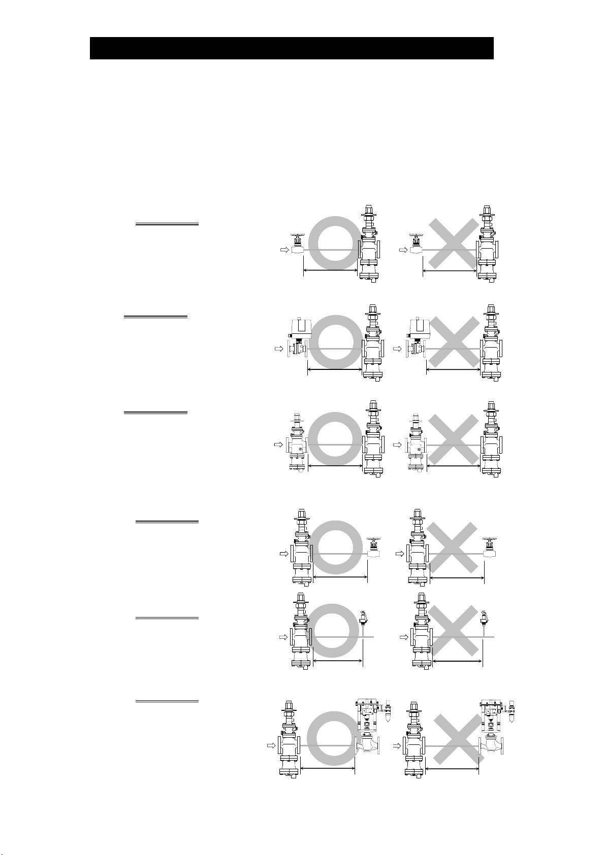
4. Precautions for the Installation of Additional Fittings Before or After the PN-COS-16
In order to ensure stable steam flow, the piping upstream and downstream of
the PN-COS-16 must be straight runs. If the PN-COS-16 is installed either
directly before or after an elbow or control valve, unevenness in steam flow
may result in chattering and unstable pressure.
To ensure stable steam flow, it is recommended that the PN-COS-16 be
installed on straight runs of piping, as illustrated below.
1) Inlet (primary side) of the PN-COS-16 (d=pipediameter)
Maintain a straight piping run
of 10 d or more when a
manual valve, a strainer or an
elbow, etc. is installed.
(Example: if nominal size is 25
mm (1 in), have 250 mm (10
in) or more)
PN-COS
Valve,
strainer,
elbow, etc.
10 d or more
PN-COS
Valve,
strainer,
elbow, etc.
Less than
10 d
Maintain a straight piping run o
f
30 d or more when an
automated valve (on-off valve)
is installed.
(Example: if nominal size is 25
mm (1 in), have 750 mm (30
in) or more)
PN-COS
Motorized
Valve
30 d or more
PN-COS
Motorized
Valve
Less than
30 d
Maintain a straight piping run o
f
30 d or more when a pressure
reducing valve is installed.
(Two-stage pressure reduction
)
(Example: if nominal size is 25
mm (1 in), have 750 mm (30
in) or more)
PN-COS
Pressure
Reducing
Valve
30 d or more
PN-COS
Pressure
Reducing
Valve
Less than
30 d
2) Outlet (secondary side) of the PN-COS-16
Maintain a straight piping run
of 15 d or more when a
manual valve, a strainer or an
elbow, etc. is installed.
(Example: if nominal size is 25
mm (1 in), have 375 mm (15
in) or more)
PN-COS Valve,
strainer,
elbow, et
c
15 d or more
PN-COS Valve,
strainer,
elbow, etc.
Less than
15 d
Maintain a straight piping run
of 30 d or more when a
safety valve is installed.
(Example: if nominal size is 2
5
mm (1 in), have 750 mm (30
in) or more)
172-65588MA-02 (PN-COS Pneumatic Control Valve) 5 Sep 2014
PN-COS Safety
Valve
30 d or more
PN-COS Safety
Valve
Less than
30 d
Maintain a straight piping run
of 30 d or more when a
control valve or an automated
valve (on-off valve) is
installed.
(Example: if nominal size is
25 mm (1 in), have 750 mm
(30 in) or more)
Control or
Automated
Valve
Control or
Automated
Valve
PN-COS
30 d or more
PN-COS
Less than
30 d
7
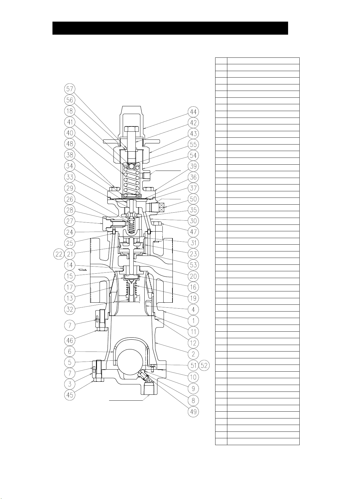
Configuration
172-65588MA-02 (PN-COS Pneumatic Control Valve) 5 Sep 2014
15 – 50 mm (1/2– 2 in)
10 mm
(3/8in)
8 mm (1/4in)
Motive Air
Port
15 mm (1/2in)
Condensate
Discharge Port
*
No. Name
1 Main Body
2 Trap Body
3 Trap Cover
4 Separator
5 Float
6 Float Cover
7 Guide Pin
8 Trap Valve Seat
9 Trap Valve Seat Gasket
10 Gasket (Trap Body/Trap Cover)
11 Wave Spring
12 Gasket (Main Body/Trap Body)
13 Separator Screen
14 Main Valve Seat
15 Main Valve Seat Gasket
16 Main Valve
17 Main Valve Holder
18 Steel Ball
19 Main Valve Spring
20 Piston
21 Piston Ring
22 Tension Ring
23 Cylinder
24 Gasket (Pilot Body/Main Body)
25 Connecting Tube
26 Pilot Screen
27 Pilot Screen Holder
28 Pilot Screen Holder Gasket
29 Pilot Valve Spring
30 Pilot Body
31 Piston Guide
32 Sleeve
33 Pilot Valve
34 Pilot Valve Seat
35 Pilot Valve Seat Gasket
36 Diaphragm
37 Diaphragm Gasket
38 Diaphragm Support
39 Spring Housing
40 Coil Spring
41 Spring Retainer
42 Adjustment Screw
43 Packing Retainer
44 Spanner Cap
45 Hex Bolt (Trap Body/Trap Cover)
46 Hex Bolt (Main Body/Trap Body)
47 Hex Bolt (Pilot Body/Main Body)
48 Hex Bolt (Spring Housing/Pilot Body)
49 Bushing
50 Plug – Sensing Line Port*
51 Float Cover Bolt
52 Spring Washer
53 Cylinder Gasket
54 Nameplate
55 C-ring
56 Gland Packing
57 O-ring
*North American model does not equip this plug.

8
Installation
Install properly and DO NOT use this product outside the recommended
operating pressure, temperature and other specification ranges.
Improper use may result in such hazards as damage to the product or
malfunctions which may lead to serious accidents. Local regulations
may restrict the use of this product to below the conditions quoted.
CAUTION
Use hoisting equipment for heavy objects (weighing approximately
20 kg (44 lb) or more). Failure to do so may result in back strain or other
injury if the object should fall.
CAUTION
Take measures to prevent people from coming into direct contact with
product outlets. Failure to do so may result in burns or other injury from
the discharge of fluids.
CAUTION
Installation, inspection, maintenance, repairs, disassembly, adjustment and valve
opening/closing should be carried out only by trained maintenance personnel.
Installation Environment
Avoid installation in the following types of environments:
Locations with ambient temperatures above 50 °C (122 °F) or below 0 °C (32 °F)*
Locations with ambient humidity above 90% RH and below 10% RH
Locations where corrosive gas is generated
Locations with heavy vibration or shock
Locations with high inductive interference or other factors that would have a
harmful effect on electrical circuitry*
*When the PN-COS-16 is used with electrical equipment such as an electro-pneumatic
transducer, controller, etc.
1. Blowdown
Before installing the PN-COS-16 unit, be
sure to blow down all piping thoroughly. If
this is not possible, perform a blowdown
using the bypass valve.
Blowdown is especially important for newly
installed piping or after the system has
been shut down for a long period of time.
PN-COS
Open
Closed Closed
Blowdown with the Bypass Valve
2. Removing Seal and Cap
Before installation, be sure to remove all protective seals and caps.
(Found in 3 locations, on the product inlet and outlets.)
①②
③
3. Installation Angle
Install the PN-COS-16 vertically, so that the arrow
mark on the body points horizontally in the direction
of steam flow.
Allowable inclination is 10 degrees in the fore-aft
direction and 15 degrees in the plane perpendicular
to the steam flow line.
15151515
10
10
10
10
172-65588MA-02 (PN-COS Pneumatic Control Valve) 5 Sep 2014
9
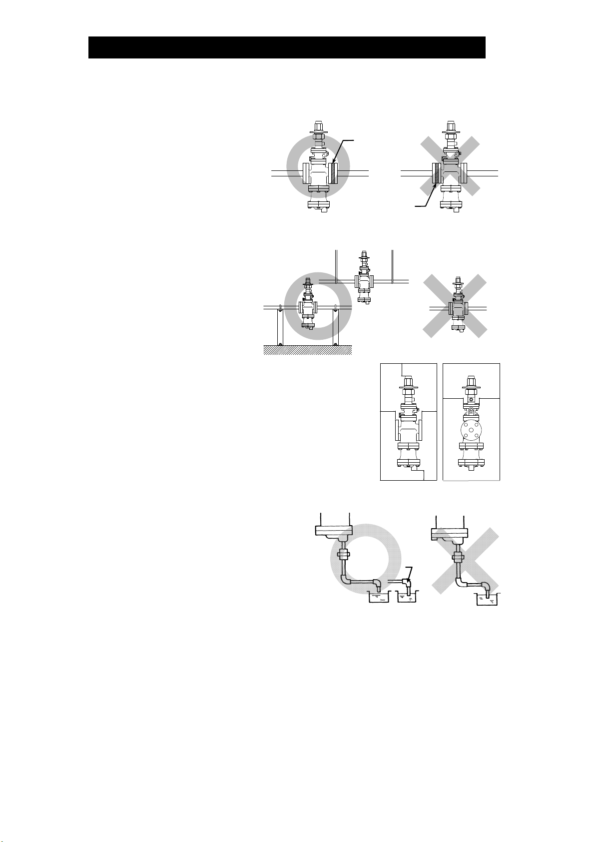
4. Spacer Installation
If spacing adjustment is
necessary to accommodate
installation, install a spacer on
the outlet flange.
The spacer should consist of a
spacer, gaskets, bolts and nuts.
Fit gaskets to both sides of the
spacer between the PN-COS-
16 outlet and the pipe flange.
Fasten with bolts and nuts.
Correct
spacer
location
Incorrect
spacer
location
5. Piping Support
Install the PN-COS-16, paying
attention to avoid excessive
load, bending and vibration.
Support the inlet and outlet
pipes securely.
6. Maintenance Space
Leave sufficient space for maintenance, inspection
and repair.
(Unit: mm (in))
200
(8)
200 (8)
150
(6)
100 (4)
150
(6)
200
(8)
7. Trap Outlet Pipe
For ease of maintenance, installation of
a union connection is recommended for
the trap outlet pipe.
Connect the outlet pipe to a condensate
return line, or extend it to a trench. In the
case of the latter, make sure the end of
the pipe is above the waterline. (Dirt and
water may be sucked up by the vacuum
formed during trap closure and system
shutdown.)
Small Hole
172-65588MA-02 (PN-COS Pneumatic Control Valve) 5 Sep 2014

10
8. Pressure Sensor Installation (for
pressure control)
The length of piping between the
PN-COS-16 and the pressure
sensor should be no more than 5 m
(17 ft). If the piping distance is too
great, pressure loss and delay of
pressure change along this distance
will increase, resulting in steam flow
rate fluctuations.
PN-COS
Pressure
Gauge
Pressure
Sensor
>>
>
>>
>
>
>
>
>
Straight
pipe
Straight
pipe
15 d or
more
5 d or
more
Distance of
5 m (17 ft) or less
Steam fluctuations at the pressure sensor may impair the stability of the pressure
control. Ensure a straight piping run of at least 15 d upstream and 5 d
downstream from the pressure sensor.
9. Blowdown Valve (requires an optional plug)
In an environment of heavy dirt or scale, or when the steam-using equipment is
used only periodically, such as for room heating equipment, be sure to use a
blowdown valve.
1) Remove the plug (option) from the main body.
2) Install the blowdown valve.
3) Open the blowdown valve and blow any residual dirt
and scale off of the screen.
4) Periodically activate the blowdown valve to keep the
system free of dirt and scale.
Remove the
10 mm (
3
/
8
in) plug
(optional)
and install the
blowdown valve
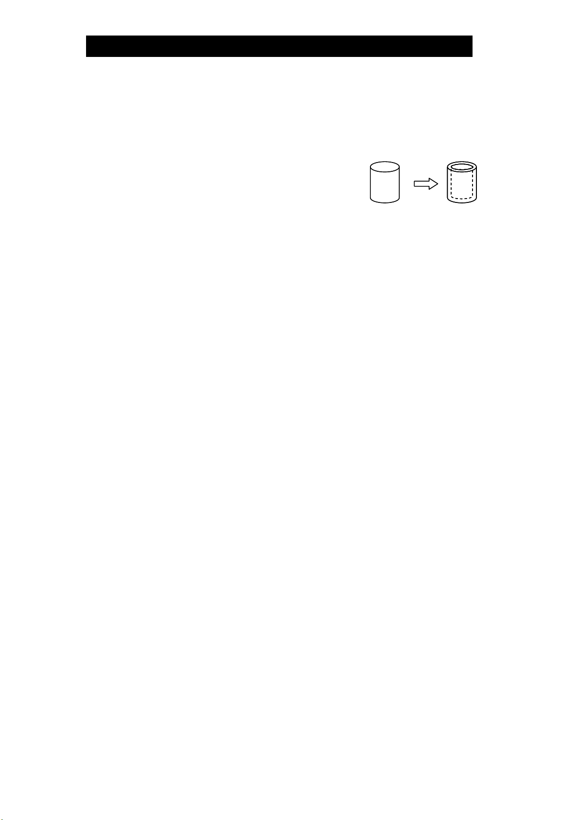
10. Piping Size
If the secondary steam flow velocity is expected to be more than 30 m/s (100 ft/s),
install a diffuser in order to keep the flow velocity below 30 m/s (100 ft/s).
If the distance between the PN-COS-16 and the steam-using equipment is great,
a possible drop in pressure should be taken into consideration when selecting the
piping size.
In addition, when installing the strainer, the strainer screen should be either at the
3 o’clock or 9 o’clock position to prevent condensate accumulation.
PN-COS
Diffuser
Straight-run piping lengths (d = pipe diameter):
PN-COS
Diffuser
Straight-run piping lengths (d = pipe diameter):
Upstream = 10 d or more; Downstream = 15 d or more
PN-COS
Diffuser
Straight-run piping lengths (d = pipe diameter):
PN-COS
Diffuser
Straight-run piping lengths (d = pipe diameter):
Upstream = 10 d or more; Downstream = 15 d or more
PN-COSPN-COS
172-65588MA-02 (PN-COS Pneumatic Control Valve) 5 Sep 2014
11
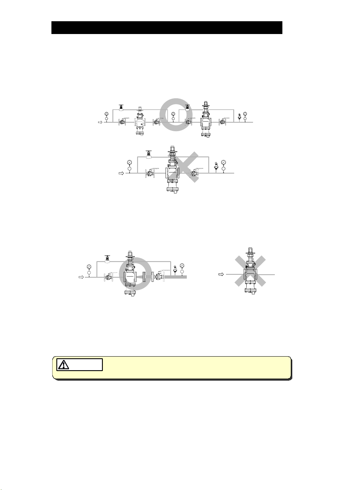
11. Two-stage Pressure Reduction
Whenever the pressure cannot be reduced to the desired level with a single PN-
COS-16 due to operating range limitations, such as when the reduction ratio is
greater than 10:1, the pressure reducing valve should be installed at the primary
side.
PN-COS
Pressure
Gauge
Pressure
Gauge
Pressure
Gauge
Bypass
Valve
Primary
Side
Shut-off
Valve
Shut-off
Valve
Pressure
Reducing
Valve
Bypass
Valve
Shut-off
Valve
Shut-off
Valve
Safety Valve
(Relief Valve)
PN-COS
Pressure
Gauge
Pressure
Gauge
Bypass
Valve
Shut-off
Valve
Shut-off
Valve
Safety Valve
(Relief Valve)
Primary
Side
12. Accessories
Always install a shut-off valve, pressure gauge and bypass line at both inlet and
outlet.
Ball valves, which will not retain condensate, are recommended for inlet and outlet
shut-off valves. The bypass pipe should be at least 1/2of the size of the inlet
(primary side) pipe.
PN-COS
Ball Valve Ball Valve
Globe
Valve Pressure
Gauge
Pressure
Gauge
PN-COSPN-COS
13. External secondary pressure-sensing line (when required)
North American Models:
North American Models are factory prepared for external sensing.
An external sensing line MUST be installed.
DO NOT SUPPLY STEAM until all piping and a 10 mm (3/8in) secondary pressure
sensing line with a slightly falling pitch have been properly installed. Install a
shutoff valve in the pressure sensing line for maintenance purposes.
Keep the shutoff valve open at all times during operation. If the shutoff
valve is closed,PN-COS-16 will fully open and PRIMARY PRESSURE WILL BE
SUPP LIED TO THE EQUIPMENT (see “Piping Example” on next page).
CAUTION
Non-North American Models:
Factory-standard PN-COS-16 employs an internal secondary pressure-sensing
channel built into the body, saving the need to install an external pressure-sensing
line to detect the secondary pressure.
Installation of an external secondary pressure-sensing line involves closing the
internal pressure-sensing channel and installing a line from the sensing line port to
the point where pressure should be controlled. This can increase stability of
pressure control where steam loss in secondary piping and flow rate fluctuation is
high. In addition, the rated flow rate will be greater than an internal pressure-
172-65588MA-02 (PN-COS Pneumatic Control Valve) 5 Sep 2014

12
sensing channel under the operational pressure reduction ratio of 2:1 or more.
Installation procedure
1) Loosen and remove the bolts that attach the pilot body to the main body and
remove the pilot body.
2) Install the blind pin (optional) by first removing the connecting tube from the
main body or pilot cover and then substituting the blind pin.
3) Re-install the pilot body and fasten the bolts evenly to the proper torque
(see the torque chart in the “Reassembly” section).
4) Remove the plug from the secondary pressure sensing line port and connect
the secondary pressure sensing line.
5) Install the secondary pressure sensing line with a slightly falling pitch. The end
of the secondary pressure sensing line should be connected to the place on
the main piping where the pressure is to be sensed (see the piping example on
the next page). A shut-off valve and union should be installed in the secondary
pressure sensing line.
Pilot Body
Body
Secondary Pressure Sensing Line Port
(Rc(PT)
3
/
8,
BSP
3
/
8
or NPT
3
/
8
)
Hex Bolt
Secondary Pressure
Sensing Port
Connecting Tube
Replace the factory-installed
connecting tube (has a hole)
with the optional blind pin
(has no hole).
Blind Pin
Connecting
Tube
Piping Example:
1 m (3.3 ft) or 15 d,
whichever is larger
Steam-using EquipmentSteam-using Equipment
PN-COS
15 d
or more
<>
<
>
10 mm (3/8 in)
Pressure Sensing Line
(with a slightly falling pitch towards
the sensing point)
Ball
Valve
172-65588MA-02 (PN-COS Pneumatic Control Valve) 5 Sep 2014
13
14. Internal sensing for North American models
All models except North American models are factory prepared for internal sensing.
When internal pressure sensing is required for North American models, please
contact the nearest TLV representative to request both a connecting tube, which
must be installed in place of the blind pin, and a threaded secondary pressure
sensing plug. Follow the connecting tube installation procedure shown below:
1) Loosen and remove the four (4) bolts that attach
the pilot body to the main body and remove the
pilot body.
2) Install the connecting tube by first removing the
blind pin from the secondary side of the main body
and then substituting the connecting tube.
Blind Pin Connecting Tube
3) Re-install the pilot body and fasten the four (4) bolts evenly.
See the torque chart in the “Reassembly” section in this manual for torque
requirements of these bolts.
4) If a secondary pressure sensing pipe has previously been installed, remove it
and be certain to install the threaded secondary pressure sensing line plug in its
place.
NOTE: When 15 mm (1/2in) or 20 mm (3/4in) PN-COS-16 is used below 0.3 MPaG
(45 psig) and 0.1 MPaG (15 psig) respectively, and below 50% of primary
pressure, internal sensing may provide decreased capacity (Rated Flow
Rate) compared to external sensing.
Verify the capacity before switching to internal sensing.
172-65588MA-02 (PN-COS Pneumatic Control Valve) 5 Sep 2014
14
Operation
Wh en u s in
g
this product, NEVER stand close to, or leave tools anywhere
near moving parts, such as the shaft. Contact with moving parts or objects
becoming caught in moving parts could lead to injury or damage or other
accidents.
CAUTION
Procedure
The system configuration examples (diagrams) shown in this section are for
explanation purposes only, and are not intended as installation designs.)
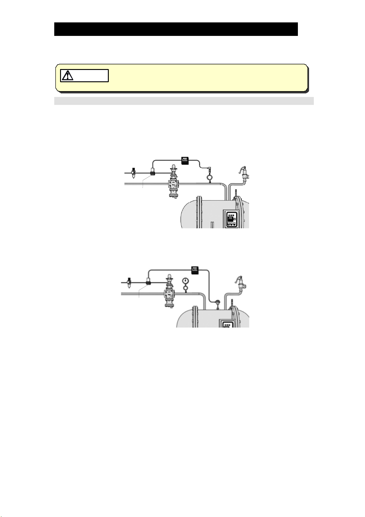
Automatic Control
<Example: Pressure control system (as control valve)>
Pressure
Transmitter
Controller
Air
Regulator
Electro-Pneumatic
Transducer
PN-COS-16
<Example: Temperature control (as control valve)>
Controller
Air
Regulator
Electro-Pneumatic
Transducer
PN-COS-16
Automatic control is possible when the PN-COS-16 is used with a controller. However,
an electro-pneumatic transducer is required in order to control the air for operation.
The wiring, etc. should be carried out according to the instruction manual for the
controller, the electro-pneumatic transducer, or related devices.
Please set the position of the adjustment screw on the PN-COS-16 according to the
steps shown in the “Setting the pressure with the adjustment screw”.
In addition, for process temperature control, the secondary pressure of the PN-COS-16
needs to be within the pressure adjustable range at the time of normal operation.
172-65588MA-02 (PN-COS Pneumatic Control Valve) 5 Sep 2014

15
Manual Control
<Example: Manual remote operation (as pressure reducing valve)>
(installed in a
high position)
Air
Regulator
(with relief)
PN-COS-16
When operating the PN-COS-16 remotely by manual operation, an air regulator (with
relief function) that adjusts motive air pressure is required. Adjust the set pressure
with the air regulator while checking the pressure gauge on the secondary side.
Please set the position of the adjustment screw according to the steps shown in the
"Setting the pressure with an adjustment screw" on the following page.
<Example: 2 point pressure switching (as pressure reducing valve)>
ON/OFF
Switch
3 Way
Solenoid Valve
A
ir Regulato
r
(with relief)
PN-COS-16
Pressure at the secondary side can be switched manually between 2 points with an
ON/OFF switch. To do so, an air regulator (with relief function), which adjusts the
motive air, a 3 way solenoid valve, and an ON/OFF switch are required.
Pressure setting at the higher pressure side should be adjusted with the motive air by
checking the pressure gauge at the secondary side. For pressure setting at the lower
pressure side, follow the steps in the "Setting the pressure with the adjustment screw"
below.
Setting the pressure with the adjustment screw
Other than setting the secondary steam pressure of PN-COS-16
using air pressure, it can be set by the adjustment screw.
・ To Maintain minimum required pressure by adjustment screw
Set the steam pressure at the secondary pressure side to a
minimum required pressure using the adjustment screw.
・ When setting the pressure using only motive air
Loosen the adjustment screw until there is no load on the coil
spring. The valve should be closed once there is no motive air.
Adjustment
Screw
172-65588MA-02 (PN-COS Pneumatic Control Valve) 5 Sep 2014

16
<Adjustment>
1. It is necessary to blow down all pipe lines thoroughly. The blowdown is especially
important if the line is new or has been shut down for a long period of time. Take
particular care to ensure that matter such as condensate and dirt does not remain
inside the steam-using equipment. (Stay clear of any pressurized blow-out from the
safety valve.)
2. Make sure that the shut-off valve and the bypass valve located upstream and
downstream of the PN-COS-16 are completely closed.
3. Remove the spanner cap and turn the adjustment screw counterclockwise to
reduce tension on the coil spring.
NOTE: Do not pull up the adjustment screw forcibly once the adjustment screw has
reached the point at which it stops. The internal stopper (C-ring) may break.
4. Slowly, fully open the shut-off valve at the inlet of the PN-COS-16. Allow sufficient
time for condensate remaining at the inlet of the PN-COS-16 to be discharged
through the built-in steam trap.
5
. Slightly open the shut-off valve at the outlet of the PN-COS-16.
6. Turn the adjustment screw clockwise until the desired outlet pressure is obtained.
Wait several minutes.
Tighten the adjustment screw
to increase pressure
Loosen the adjustment screw
to decrease pressure
Clockwise Counterclockwise
7. Slowly, fully open the shut-off valve at the secondary side of the PN-COS-16. After
setup, put the spanner cap back on.
8. When shutting down the system, always close the shut-off valve at the outlet first
and then the inlet.
172-65588MA-02 (PN-COS Pneumatic Control Valve) 5 Sep 2014
17
Maintenance
Take measures to prevent people from coming into direct contact with
product outlets. Failure to do so may result in burns or other injury from
the discharge of fluids.
CAUTION
Be sure to use only the recommended components when repairing the
product, and NEVER attempt to modify the product in any way. Failure to
observe these precautions may result in damage to the product or burns
or other injury due to malfunction or the discharge of fluids.
CAUTION
Make sure the external power supply switch is OFF before carrying out
work on the wiring or inspections involving disassembly.
If such work is carried out with the power on, there is a danger that
equipment may malfunction or electric shock may occur, leading to
injury or other accidents.
CAUTION
Operational Check
To ensure long service life of the PN-COS-16, the following inspection and
maintenance should be performed regularly.
Part Inspection and Maintenance Frequency
Screens
(Separator, Pilot)
Disassemble and clean annually.
If there is substantial blockage, install a strainer
(approximately 60 mesh) ahead of the PN-COS-16.
Main Valve, Main Valve
Seat, Pilot Valve and Pilot
Valve Seat
Replace after approximately 15,000 hours.
If there is chattering or dirt, premature wear may result.
Piston Ring Replace after approximately 8,000 hours.
If there is chattering or if scale build-up is severe,
premature wear may result.
Piston Replace after approximately 30,000 hours.
If hunting or chattering takes place, premature wear may
result.
Trap Valve Seat Replace after approximately 40,000 hours.
If scale build-up is severe, blockage may occur in a short
period of time.
Diaphragm Replace after approximately 30,000 hours.
If hunting or chattering takes place, cracks or fatigue may
develop in a short period of time.
172-65588MA-02 (PN-COS Pneumatic Control Valve) 5 Sep 2014
18
Disassembly
NEVER apply direct heat to the float. The float may explode due to
increased internal pressure, causing accidents leading to serious injury
or damage to property and equipment.
WARNING
Use hoisting equipment for heavy objects (weighing approximately
20 kg (44 lb) or more). Failure to do so may result in back strain or other
injury if the object should fall.
CAUTION
When disassembling or removing the product, wait until the internal
pressure equals atmospheric pressure and the surface of the product
has cooled to room temperature. Disassembling or removing the
product when it is hot or under pressure may lead to discharge of fluids,
causing burns, other injuries or damage.
CAUTION
It is a recommended practice to dismantle and inspect the PN-COS-16 once a year for
preventive maintenance purposes. It is especially important to perform an inspection
immediately after the initial run of a new line or before or after equipment such as a
heater is out of service for a long period of time. (Installation, inspection, maintenance,
repairs, disassembly, adjustment and valve opening/closing should be carried out only
by trained maintenance personnel.)
Remove all steam from the piping (both upstream and downstream). Stop supplying
motive air to the PN-COS-16. Remove the spanner cap, and then pull up the
adjustment screw until there is no load on the coil spring. Wait for the body to cool
before attempting to remove the PN-COS-16 from the line as it may be heated with the
residual heat of steam. Then remove the inlet and outlet flange retaining bolts and
nuts to permit removal of the PN-COS-16. Secure the PN-COS-16 in a vise to perform
the inspection.
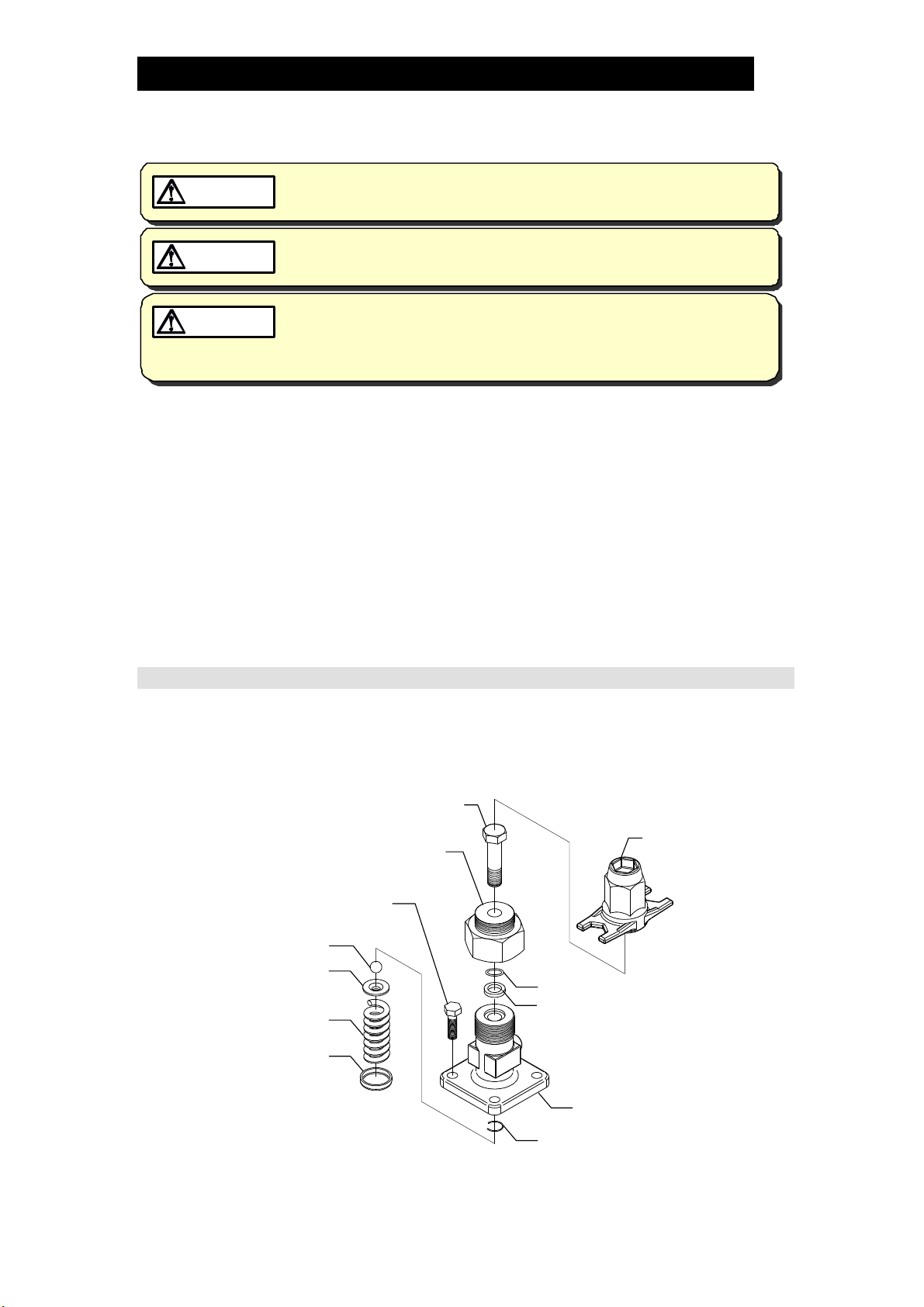
Disassembling the Adjustment Section (Drive Section)
Make sure that the position of the adjustment screw is such that no load is applied to
the coil spring.
Remove the hex bolts and then take off the spring housing. Remove the C-ring with
an appropriate tool to remove the adjustment screw. Remove the adjustment screw by
loosening it. Then remove the packing retainer by turning it counterclockwise.
Spanner Cap
Adjustment Screw
Spring Housing
Ball
Hex Bolt
O-ring
Packing Retainer
Gland Packing
C-ring
Spring Retainer
Coil Spring
Diaphragm Support
NOTE: Make sure that there are no scratches or wear on the internal parts. Do not reuse the
O-ring and the gland packing.
172-65588MA-02 (PN-COS Pneumatic Control Valve) 5 Sep 2014
19
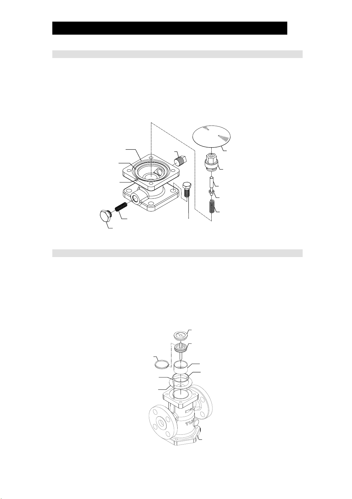
Disassembling the Pilot Section
The diaphragm is removed by utilizing the notch in the pilot body. Loosen the pilot valve
seat with a box wrench and remove it. Lift the pilot valve spring up and out with a pair of
tweezers. Then loosen and remove the pilot screen holder to remove the pilot screen.
Check for any fault on the seating surface of the pilot valve, flaws on the gaskets,
and clogging of the pilot screen.
Check for deformation, corrosion or faults on the diaphragm. The diaphragm should
be convex (open downward), with the printed UP mark on the top.
Diaphragm
Pilot Valve Seat
(with Gasket)
Pilot Valve Stem
Pilot Valve
Pilot Valve Spring
Hex Bolt
Pilot Body
Upper
Pilot Body
Gasket
Notch
Pilot Screen
Pilot Screen Holder
(with Gasket)
Plug
Disassembling the Piston Section
Take the pilot body off after removing the hex bolts. During this process, pay attention
not to lose the connecting tubes (2 pcs).
Remove the piston guide, piston and cylinder from the main body. Then remove the
piston rings and the tension rings from the piston. Do not apply too much force when
removing the piston rings and tension rings.
Check the interior of the cylinder, the exterior of the piston rings, the small hole on
the piston and the cylinder gasket for any fault or abnormality.
Piston Guide
Piston
Connecting Tube
Piston Ring
Tension Ring Cylinder
Cylinder Gasket
Lower Pilot
Body Gasket
Main Body
172-65588MA-02 (PN-COS Pneumatic Control Valve) 5 Sep 2014
Table of contents
Other TLV Control Unit manuals


Popular Control Unit manuals by other brands

Meltem
Meltem M-WRG-II installation manual

CLA-VAL
CLA-VAL 50B-4KG1 Installation, operation and maintenance

Mankenberg
Mankenberg DM 462V Original operating manual

Spirax Sarco
Spirax Sarco DN15 Installation and maintenance instructions

Bose
Bose ControlSpace CC-4 installation guide

Emerson
Emerson Raimondi HPA 150 Installation & maintenance instructions

IBM
IBM color LaserJet 5500 Operational, installation, and maintenance guide

BFT
BFT SIRIO FR-TMA Installation and user manual

Fancom
Fancom IMS manual

Comelit
Comelit Simplebus Color 5714C Technical manual

Emerson
Emerson ANDERSON GREENWOOD PILOT 9300 Series Installation and maintenance instructions

Allen-Bradley
Allen-Bradley 1336 PLUS II quick start guide


