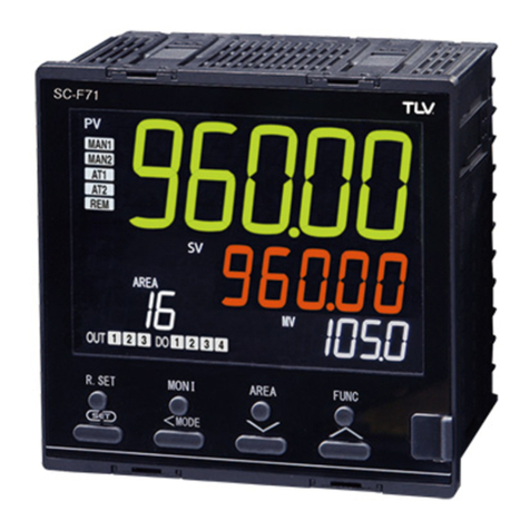
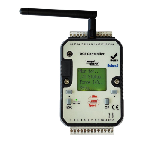
TLV SC-F71 User manual

172-65710M-04 (SC-F71 Parameters/Functions) 23 December 2021
Multi-purpose Controller
SC-F71
(Parameters/Functions)
Copyright © 2021 by TLV CO., LTD.
All rights reserved

172-65710M-04 (SC-F71 Parameters/Functions) 23 Dec 2021
1
Contents
Introduction....................................................................................4
Pictorial table of contents...............................................................5
Safety Considerations....................................................................6
Notice............................................................................................8
Notice Regarding the Export Trade Control Order (Japan)............8
Disposal.........................................................................................8
Symbols.........................................................................................9
Document Configuration..............................................................11
1. Mode Switching.......................................................................12
2. Selecting Parameters ..............................................................14
2.1 Monitor & SV Setting Mode [A]........................................................... 14
2.2 Parameter Select Mode [B]................................................................. 18
2.3 Operation Transfer Mode [C].............................................................. 19
2.4 Setting Lock Mode [D] ........................................................................ 20
2.5 Memory Area Transfer Mode [E] ........................................................ 21
2.6 Parameter Setting Mode [F]................................................................ 22
2.7 Setup Setting Mode [G]...................................................................... 24
2.8 Engineering Mode [H]......................................................................... 27
3. Parameter................................................................................37
3.1 How to Read the Table....................................................................... 37
3.2 Monitor & SV Setting Mode [A]........................................................... 38
3.3 Parameter Select Mode [B]................................................................. 40
3.4 Operation Transfer Mode [C].............................................................. 40
3.5 Setting Lock Mode [D] ........................................................................ 41
3.6 Memory Area Transfer Mode [E] ........................................................ 41
3.7 Parameter Setting Mode [F]................................................................ 42
3.8 Setup Setting Mode [G]...................................................................... 49
3.9 Engineering Mode [H]......................................................................... 54
4. ParametersthatareInitialized/Modifiedwhen SettingsareChanged 79
4.1 Parameters to Be Initialized................................................................ 79
4.2 Parameters to Be Automatically Converted........................................ 93
5. Input Function........................................................................105
5.1 Changing Measured Input Settings .................................................. 105
5.2 Switching Functions Using Digital Inputs (DI)................................... 114
5.3 Correcting Input................................................................................ 124
5.4 Preventing the Input Flicker.............................................................. 127
5.5 Inverting the Input............................................................................. 128
5.6 Extracting Square Root of Input........................................................ 131
5.7 Changing Error Handling at Input Error ............................................ 134
5.8 Using Dual Input Function ................................................................ 141
6. Output Function.....................................................................143
6.1 Changing Output Assignment [Control Output, Retransmission Output,
Logic Calculation (Event) Output, Instrument Status Output] ................. 143
6.2 Changing Output Type of OUT3....................................................... 151
6.3 Using Retransmission Output........................................................... 153

172-65710M-04 (SC-F71 Parameters/Functions) 23 Dec 2021
2
6.4 Changing Proportional Cycle Time................................................... 158
6.5 Changing Energizing/De-energizing Output ..................................... 160
6.6 Limiting Output ................................................................................. 161
6.7 Suppressing Sudden Change in Output (Output Change Rate Limiter)... 165
6.8 Suppressing Sudden Change in Output (Balanceless Bumpless).... 168
6.9 Changing the Output Action While in Control Stop Mode................. 172
6.10 Monitoring Manipulated Output Value ............................................ 175
7. Event Function.......................................................................176
7.1 Using Event Function ....................................................................... 176
7.2 Checking Event ON State................................................................. 192
7.3 Keeping the Event State (Interlock Function) ................................... 193
7.4 Releasing the Event State (Interlock Release)................................. 194
7.5 Preventing Control with Input Errors (Input Circuit Error Alarm)....... 196
8. Control Function....................................................................199
8.1 Running/Stopping Control (RUN/STOP Transfer) ............................ 199
8.2 Changing Control Action................................................................... 201
8.3 Setting PID Values Automatically (Autotuning)................................. 207
8.4 Setting PID Values Automatically (Startup tuning)............................ 213
8.5 Setting PID Values Manually............................................................ 218
8.6 Controlling with ON/OFF Action........................................................ 224
8.7Controlling with Heating/Cooling Control .......................................... 229
8.8 Using with MC-COS/MC-VCOS........................................................ 236
8.9 Controlling with Manual Control........................................................ 257
8.10 Using Remote Setting Input............................................................ 260
8.11 Executing 2-loop control................................................................. 264
8.12 Executing Differential temperature control...................................... 267
8.13 Executing Control with PV select.................................................... 271
8.14 Executing Cascade Control............................................................ 280
8.15 Controlling with Level PID............................................................... 293
8.16 Eliminating Offset Inherent to Proportioning Control (Manual Reset)..... 303
8.17 Continuing Stable Control after the Operation Transfer (SV Tracking)... 304
8.18 Suppressing Overshoot.................................................................. 310
8.19 Changing the Action at Power ON (Hot/Cold Start)........................ 316
9. Display-related Functions ......................................................320
9.1 Grouping Necessary Screens (Parameter Select Function)............. 320
9.2 Hiding Unnecessary Screens ........................................................... 331
9.2.1 Hide the monitor screen in the Monitor & SV setting mode ........... 331
9.2.2 Hiding screens in Operation transfer mode ................................... 333
9.2.3 Hiding the screen using the Blind function..................................... 334
9.3 Hiding the Display of the Set Value (SV).......................................... 335
9.4 Changing the Display Position of STOP during the Control Stop ..... 337
9.5 Changing the ALM Lamp Lighting Condition .................................... 338
9.6 Changing the Display Contents of the MV Display ........................... 340
9.7 Checking Input Peak Value/Bottom Value........................................ 341
9.8 Suppressing the Display Flickering................................................... 343
9.9 Checking the Instrument Information................................................ 344
10. Setting and Key Operation...................................................347
10.1 Limiting the Setting Range of Set Value (SV)................................. 347
10.2 Eliminating a Sudden Set Value Change (Setting Change Rate Limiter) 350

172-65710M-04 (SC-F71 Parameters/Functions) 23 Dec 2021
3
10.3 Storing the Control Related Set Values (Memory Area Function)... 360
10.4 Copying the Data in Memory Area to Set Other Areas................... 364
10.5 Running a Simple Ramp/Soak Control........................................... 366
10.6 Using a Simple Sequence Operation.............................................. 373
10.7 Registering a Set Value (SV) Without Pressing the SET Key......... 380
10.8 Accessing Some Functions Directly (FUNC Key)........................... 381
10.9 Restricting Key Operation (Set Data Lock)..................................... 384
10.10 Initializing the Set Data................................................................. 386
Product Warranty.......................................................................388
Service ......................................................................................389

172-65710M-04 (SC-F71 Parameters/Functions) 23 Dec 2021
4
Introduction
Thank you for purchasing the TLV multi-purpose controller.
This product has been thoroughly inspected before being shipped from the factory.
When the product is delivered, before doing anything else, check the specifications
and external appearance to make sure nothing is out of the ordinary. Also be sure to
read this manual carefully before use and follow the instructions to be sure of using
the product properly.
If detailed instructions for special order specifications or options not contained in this
manual are required, please contact TLV for full details.
This instruction manual is intended for use with the model(s) listed on the front cover.
It is necessary not only for installation but for subsequent maintenance, disassembly/
reassembly and troubleshooting. Please keep it in a safe place for future reference.
Microsoft Windows is a trademark of Microsoft Corporation (in the United States and other
countries).
MODBUS is a registered trademark of Schneider Electric SA.
All product names mentioned are trademarks or registered trademarks of the respective
companies [owners].

172-65710M-04 (SC-F71 Parameters/Functions) 23 Dec 2021
5
Pictorial table of contents
Sections describing hardware shown below.

172-65710M-04 (SC-F71 Parameters/Functions) 23 Dec 2021
6
Safety Considerations
Read this section carefully before use and be sure to follow the instructions.
Installation, inspection, maintenance, repairs, disassembly, adjustment and valve
opening/closing should be carried out only by trained maintenance personnel.
The precautions listed in this manual are designed to ensure safety and prevent
equipment damage and personal injury. For situations that may occur as a result of
erroneous handling, three different types of cautionary items are used to indicate
the degree of urgency and the scale of potential damage and danger: DANGER,
WARNING and CAUTION.
The three types of cautionary items above are very important for safety: be sure to
observe all of them as they relate to installation, use, maintenance, and repair.
Furthermore, TLV accepts no responsibility for any accidents or damage occurring
as a result of failure to observe these precautions.
Symbols
Indicates a DANGER, WARNING or CAUTION item.
Indicates an urgent situation which poses a threat of death or
serious injury
Indicates that there is a potential threat of death or serious injury
such as electrical shock, fire (burns), etc.
Indicates that there is a possibility of injury or equipment/product
damage
To prevent injury to persons, damage to the instrument and the
equipment, a suitable external protection device shall be
required.
All wiring must be completed before power is turned on to
prevent electric shock, fire or damage to the instrument and the
equipment.
This instrument must be used in accordance with the
specifications to prevent fire or damage to the instrument and
the equipment.
This instrument is not intended for use in locations subject to
flammable or explosive gases.
Do not touch high-voltage connections such as power supply
terminals, etc. to avoid electric shock.
TLV is not responsible if this instrument is repaired, modified or
disassembled by non-factory-approved personnel. Malfunction
may occur and warranty is void under these conditions.
Continued on the next page
DANGER
WARNING
CAUTION
WARNING

172-65710M-04 (SC-F71 Parameters/Functions) 23 Dec 2021
7
This product is intended for use with industrial machines, test and
measuring equipment. (It is not designed for use with medical
equipment and nuclear energy plant.)
This is a Class A instrument. In a domestic environment, this
instrument may cause radio interference, in which case the user
may be required to take additional measures.
This instrument is protected from electric shock by reinforced
insulation. Provide reinforced insulation between the wire for
the input signal and the wires for instrument power supply,
source of power and loads.
Be sure to provide an appropriate surge control circuit
respectively for the following:
- If input/output or signal lines within the building are longer than
30 meters.
- If input/output or signal lines leave the building, regardless of the
length.
This instrument is designed for installation in an enclosed
instrumentation panel. All high-voltage connections such as
power supply terminals must be enclosed in the instrumentation
panel to avoid electric shock to operating personnel.
All precautions described in this manual should be taken to
avoid damage to the instrument or equipment.
If the equipment is used in a manner not specified by the
manufacturer, the protection provided by the equipment may be
impaired.
All wiring must be in accordance with local codes and regulations.
To prevent instrument damage as a result of failure, protect the
power line and the input/output lines from high currents with a
suitable overcurrent protection device with adequate breaking
capacity such as a fuse, circuit breaker, etc.
A malfunction in this product may occasionally make control
operations impossible or prevent alarm outputs, resulting in a
possible hazard. Take appropriate measures in the end use to
prevent hazards in the event of malfunction.
Prevent metal fragments or lead wire scraps from falling inside
instrument case to avoid electric shock, fire or malfunction.
Tighten each terminal screw to the specified torque found in the
manual to avoid electric shock, fire or malfunction.
For proper operation of this instrument, provide adequate
ventilation for heat dissipation.
Do not connect wires to unused terminals as this will interfere with
proper operation of the instrument.
Turn off the power supply before cleaning the instrument.
Do not use a volatile solvent such as paint thinner to clean the
instrument. Deformation or discoloration may occur. Use a soft,
dry cloth to remove stains from the instrument.
To avoid damage to the instrument display, do not rub with an
abrasive material or push the front panel with a hard object.
CAUTION

172-65710M-04 (SC-F71 Parameters/Functions) 23 Dec 2021
8
Notice
This manual assumes that the reader has a fundamental knowledge of the principles
of electricity, process control, computer technology and communications.
The figures, diagrams and numeric values used in this manual are only for
explanation purpose.
TLV is not responsible for any damage or injury that is caused as a result of using
this instrument, instrument failure or indirect damage.
TLV is not responsible for any damage and/or injury resulting from the use of
instruments made by imitating this instrument.
Periodic maintenance is required for safe and proper operation of this instrument.
Some components have a limited service life, or characteristics that change over
time.
Every effort has been made to ensure accuracy of all information contained herein.
TLV makes no warranty, expressed or implied, with respect to the accuracy of the
information. The information in this manual is subject to change without prior notice.
No portion of this document may be reprinted, modified, copied, transmitted,
digitized, stored, processed or retrieved through any mechanical, electronic, optical
or other means without prior written approval from TLV.
Various symbols are used on the equipment, and they have the following meaning.
: Alternating current
: Direct current
: Reinforced insulation
: Safety precaution
This symbol is used where the instruction manual needs to be consulted for the
safety of both the operator and the equipment. Carefully read the cautions in this
manual before using the instrument.
Notice Regarding the Export Trade Control Order
(Japan)
The intended application and end user should be checked to make sure this product
will not be used in weapons of mass destruction, military applications or military
equipment etc.
Take precautions not to allow this product to be illegally exported, even in the case of
reselling or distribution.
Disposal
When disposing of each part used for this instrument, always follows the procedure
for disposing of industrial wastes stipulated by the respective local municipality.
!

172-65710M-04 (SC-F71 Parameters/Functions) 23 Dec 2021
9
Symbols
Pictorial Symbols (safety symbols)
This icon indicates important information on installation, handling
and operating procedures.
This icon indicates supplemental information on installation,
handling and operating procedures.
This icon indicates where additional information may be located.
Character Symbols
11-segment character
0
1
2
3
4
5
6
7
8
9
Minus
Period
0
1
2
3
4
5
6
7
8
9
-
.
A
B (b)
C
c
D (d)
E
F
G
H
I
J
K
A
b
C
c
D
E
F
G
H
I
J
K
L
M
N
n
O (o)
P
Q
R
S
T
t
U
L
M
N
n
o
P
Q
R
S
T
t
U
u
V
W
X
Y
Z
Degree
/
Prime
*
(Asterisk)
→
u
V
W
X
Y
Z
@
/
`
Š
‹
7-segment character
0
1
2
3
4
5
6
7
8
9
Minus
Period
0
1
2
3
4
5
6
7
8
9
-
.
A
B (b)
C
c
D (d)
E
F
G
H
I
J
K
A
b
C
c
D
E
F
G
H
I
J
K
L
M
N (n)
O (o)
P
Q
R
S
T
t
U
u
L
M
n
o
P
Q
R
S
T
t
U
u
V
W
X
Y
Z
Degree
/
Prime
*
(Asterisk)
V
W
X
Y
Z
@
`
Š
NOTE

172-65710M-04 (SC-F71 Parameters/Functions) 23 Dec 2021
10
Abbreviation symbols
These abbreviations are used in this manual:
Abbreviation
symbols
Name
Abbreviation
symbols
Name
PV
Measured value
TC (input)
Thermocouple (input)
SV
Set value
RTD (input)
Resistance temperature
detector (input)
MV
Manipulated output value
AT
Autotuning
V (input)
Voltage (input)
ST
Startup tuning
I (input)
Current (input)
OUT (1 to 3)
Output (1 to 3)
HBA (1, 2)
Heater break alarm (1, 2)
DI (1 to 6)
Digital input (1 to 6)
CT (1, 2)
Current transformer (1, 2)
DO (1 to 4)
Digital output (1 to 4)
LBA
Control loop break alarm
FBR
Feedback resistance
LBD
LBA deadband
V/I
Voltage (V)/Current (I)
Screens used in this manual
The SC-F71 has two inputs. Following input type is available by setting parameters:
Dual PV (PV + PV) type or PV + Remove setting type. The input type is set to PV +
Remote setting type when shipped from the factory.
For a dual input model, the same parameter may exist in both Input 1 and Input 2.
“1.” or “2.” is added to the top of the parameters for identification. “1.” is not added to
the top of the parameters list for the single input type.
Display example of the dual input type:
Input 1_Set value (SV)
Input 2_Set value (SV)
Display example of a single input type:
Set value (SV)
This manual uses the dual inputs for explanation. For other types such as a single
input type, ignore the first character “1.” at the top of the parameter.
The parameters used only for the dual input type are displayed in the colored
background ( ).
Notation in this manual:
Input 1_Set value (SV)
Input 2_Set value (SV)
In 2. Selecting Parameters, two types of frames are used to distinguish different
parameter conditions as follows.
Parameters to be always displayed
Parameter to be displayed when display condition is satisfied
1. SV
2. SV
SV
2. SV
Parameter shown only
on the dual input type

172-65710M-04 (SC-F71 Parameters/Functions) 23 Dec 2021
11
Document Configuration
There are seven manuals pertaining to this product. Please be sure to read all
manuals specific to your application requirements.
Contact TLV for the following manuals.
Manual
Document
Number
Remarks
Multi-purpose Controller SC-
F71 Quick Start Guide
172-65706M
This manual is enclosed with instrument.
This manual explains the basic key
operation, mode menu, and data setting.
Multi-purpose Controller SC-
F71 Installation Manual
172-65707M
This manual is enclosed with instrument.
This manual explains the mounting and
wiring.
Multi-purpose Controller SC-
F71 Parameter List
172-65708M
This manual is enclosed with instrument.
This list is a compilation of the
parameter data of each mode.
Multi-purpose Controller SC-F71
Instruction Manual
[Hardware]
172-65709M
This manual describes installation,
wiring, troubleshooting and product
specification.
Multi-purpose Controller
SC-F71 Instruction Manual
[Parameters/Functions]
172-65710M
The manual you are reading now.
Parameters:
This manual describes how to switch
the operation modes and parameters,
the range of parameters, and
initialization/automatic conversion
associated with the change of
settings.
Functions:
This manual describes how to set up
and each function.
Multi-purpose Controller SC-
F71 Instruction Manual
[Host Communication]
172-65711M
This manual explains original
communication protocol and Modbus
relating to communication parameters
setting.
Multi-purpose Controller SC-
F71 Instruction Manual
[PLC Communication]
172-65712M
This manual describes how to set up the
instrument for communication with a
programmable controller (PLC).
Read this manual carefully before operating the instrument. Please place the
manual in a convenient location for easy reference.

172-65710M-04 (SC-F71 Parameters/Functions) 23 Dec 2021
12
1. Mode Switching
This chapter describes various modes and how to switch between them.
Mode switching
The instrument has eight different modes for operation and setting. Modes can be
switched through the key operation of and keys.
MODE

172-65710M-04 (SC-F71 Parameters/Functions) 23 Dec 2021
13
Model, Input type, Unit and Input range
Immediately after the instrument is turned on, the input type, the unit symbol and the
input range will be displayed.
Example: Thermocouple input (type K) and -200 to 1372 C
Table 1: Inputtype symbol
Symbol
Input type
K
Thermocouple K
J
Thermocouple J
T
Thermocouple T
S
Thermocouple S
R
Thermocouple R
E
Thermocouple E
b
Thermocouple B
n
Thermocouple N
P
Thermocouple PLII
W
Thermocouple
W5Re/W26Re
U
Thermocouple U
L
Thermocouple L
Pr
Thermocouple PR40-20
PT
RTD Pt100
JP
RTD JPt100
V
Voltage
I
Current
Power ON
SC-
F71
1.INP
@C K
1372
- 200
2.INP
@C K
1372
- 200
Model: SC-F71
Input 1_Input symbol
Unit of input 1:
Temperature input: °C or °F
Voltage/Current input: No display
Input type for input 1
(Refer to Table 1)
Input 1_Input range high
Input 1_Input range low
Unit for input 2 and Input type
for input 2
(Refer to Input 1 for the
displayed contents.)
Input 2_Input range high and
Input 2_Input range low
28
0
Input 1_Measured value (PV)/
Input 1_Set value (SV)
Monitor & SV setting mode
Automatically (in 1 second)
Automatically (in 1 second)*
Automatically (in 1 second)
Automatically (in 1 second)
Automatically (in 1 second)*
* Displayed for 2 seconds (Single input type)
Parameter select mode
The first selected screen is
displayed.
or

172-65710M-04 (SC-F71 Parameters/Functions) 23 Dec 2021
14
2. Selecting Parameters
This chapter describes various parameter types and how to switch between them.
2.1 Monitor & SV Setting Mode [A]
When the Monitor and SV setting mode is entered, there are 4 (four) display contents
depending on the control. Each display also differs between the Auto mode and the
Manual mode.
1-loop control (including Remote setting input/Input circuit error alarm)
2-loop control/Cascade control
Control with PV select
Differential temperature control
1-loop control (including Remote setting input/Input circuit error alarm)

172-65710M-04 (SC-F71 Parameters/Functions) 23 Dec 2021
15
2-loop control/Cascade control
Control with PV select

172-65710M-04 (SC-F71 Parameters/Functions) 23 Dec 2021
16

172-65710M-04 (SC-F71 Parameters/Functions) 23 Dec 2021
17
Differential temperature control

172-65710M-04 (SC-F71 Parameters/Functions) 23 Dec 2021
18
2.2 Parameter Select Mode [B]
Displays the screens registered in Parameter select setting.
The display can be switched in the reverse order when the R.SET key is
pressed.
While the Blind function is activated, only Parameter select setting screen, Set
data lock mode, and PV/SV monitor* screens are displayed. The instrument
starts from the Parameter select mode after being turned on.
* The PV/SV monitor includes SV setting mode and Manual manipulated output value
setting.

172-65710M-04 (SC-F71 Parameters/Functions) 23 Dec 2021
19
2.3 Operation Transfer Mode [C]
The display can be switched in the reverse order when the R.SET key is pressed.
Use the or key to switch modes (no SET key operation required),
and a status indicator lights up or blinks if there is a status indicator
corresponding to the mode.
2.ATU
1.STU
2.STU
2.A/M
R/L
L/E
R/S
1.ATU
1.A/M
Monitor & SV setting mode
<MODE (2 seconds)
RUN/STOP
transfer
Input 1_
Autotuning
(AT)
Input 2_
Autotuning
(AT)
Input 1_
Startup
tuning (ST)
Input 2_
Startup
tuning (ST)
Input 1_
Auto/Manual
transfer
Input 2_
Auto/Manual
transfer
Remote/local
transfer*
Control area
Local/External
transfer
SET or <MODE
SET or <MODE
SET or <MODE
SET or <MODE
SET or <MODE
SET or <MODE
SET or <MODE
SET or <MODE This parameter is displayed when any of the following
is selected in Select function for input 2: "Remote
setting input", "Cascade control", "Control with PV
select", or "2-loop control/Differential temperature
control".
*
Return to
RUN/STOP
transfer
Other manuals for SC-F71
2
Table of contents
Other TLV Controllers manuals
Popular Controllers manuals by other brands
Honeywell
Honeywell LKS 310 Instruction handbook
Nemtek
Nemtek SOL-REG140 user manual
Ducasa
Ducasa Smart Command Installation and operating manual
YASKAWA
YASKAWA CIPR-GA70C Series Initial Steps
elero
elero InDrive M30/1.6 RH Operating and assembly instructions
FMC Technologies
FMC Technologies Sening EPE2 installation manual

