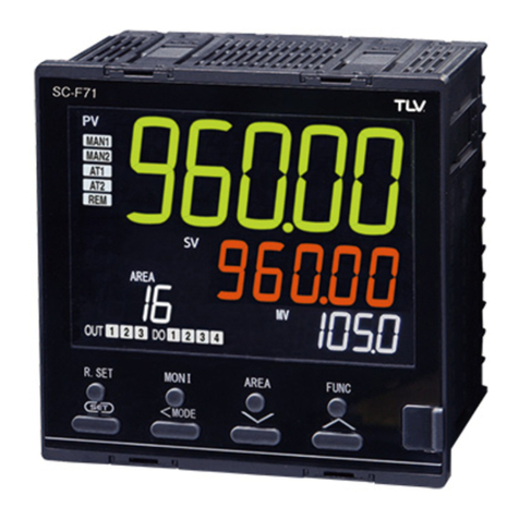
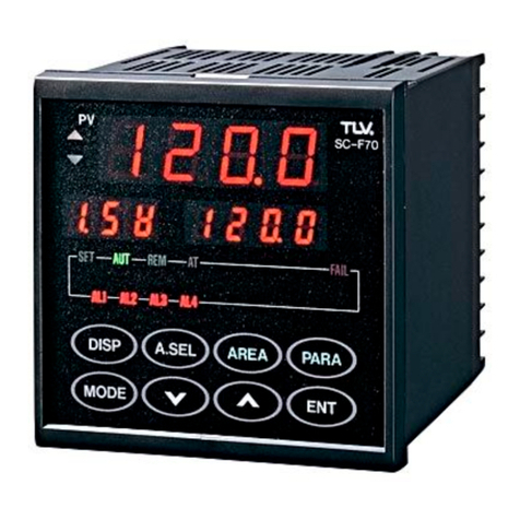
TLV SC-F70 User manual

Multicontroller
SC-F70SC-F70
Auto-Tuning PID
and
Heating, Cooling PID
Operating Instructions
Manufacturer
172-65281M-00

2
SC-F70SC-F70
PID Operation Operating Instructions
Table of Contents
Preface....................................................................................................... 4
For Your Safety ........................................................................................ 4
Checking the Model Code and Accessories ............................................ 5
1. Introduction and Installation ................................................................ 6
1.1 How to Use This Book ................................................................. 6
1.2 Setting Feature Jumpers ............................................................... 7
1.3 Attaching to the Panel .................................................................. 9
1.4 Wiring Procedure ........................................................................ 11
2. Using the Panel................................................................................... 17
2.1 Names and Functions on the Panel ............................................ 17
2.2 Guides for Using Keys ............................................................... 19
3. Operation ............................................................................................ 28
3.1 Setting Up the Basic Parameters ................................................ 28
3.2 Test Operation (LOC/MAN Mode) ........................................... 37
3.3 Automatic Operation (LOC/AUT Mode) .................................. 43
3.4 Area Switching Automatic Operation (LOC/AUT Mode) ........ 46
3.5 Compensation for Control Responsiveness ................................. 51
3.6 PID Constants Fine-Tuning Method ........................................... 52
3.7 PID Constants Setting and Control Operation ............................ 53
4. Remote Operation (REM/AUT Mode) .............................................. 55
4.1 Remote Analog Setting Operation ............................................. 55
4.2 Remote Area Switching Operation ............................................ 58
5. Using Other Functions ....................................................................... 62
5.1 Using Alarms. ............................................................................. 62
5.2 Using the Transmission Output.................................................. 65
5.3 Using the Communications Function......................................... 66
5.4 Using Other Convenient Features .............................................. 66
5.5 What Happens When Power Is Lost .......................................... 67
6. Summary of Parameter Groups and Areas ........................................ 68
6.1 Parameters ................................................................................... 68
6.2 Areas ........................................................................................... 81
7. Troubleshooting.................................................................................. 84
7.1 Problem Area .............................................................................. 84
7.2 Error Displayable Controller Problems ..................................... 89
7.3 No Error-Displayable Problems ................................................. 92
7.4 Actuator Control Problems......................................................... 95
7.5 Sensor Problems ......................................................................... 96
7.6 Area Switching External Contact Problems .............................. 99
7.7 External Analog Input Problems .............................................. 100
7.8 Communication Problems ........................................................ 101

3
SC-F70SC-F70
PID Operation Operating Instructions
7.9 Other Problems ......................................................................... 102
8. PID Constants Manual Tuning Method ........................................... 103
8.1 Step Response Method ............................................................. 103
8.2 Ultimate Sensitivity Method .................................................... 105
9. Specifications ................................................................................... 106
9.1 Display Functions ..................................................................... 106
9.2 Measurement Input ................................................................... 106
9.3 Settigns...................................................................................... 107
9.4 Control Operation ..................................................................... 108
9.5 Control Output .......................................................................... 108
9.6 Alarm Ouput ............................................................................. 110
9.7 Transmission Output................................................................. 111
9.8 External Contact Input.............................................................. 111
9.9 Communication Output ............................................................ 112
9.10 Self-Diagnostic Function........................................................ 114
9.11 General Specifications............................................................ 115
9.12 Environmental Conditions (Normal Operation) .................... 115
9.13 Shipping and Storage Conditions........................................... 116
10. Product Warranty.............................................................................. 117

4
SC-F70SC-F70
PID Operation Operating Instructions
Preface
Thank you for choosing the
SC-F70SC-F70
Multicontroller, a
multipurpose, multifunction, easy-to-use controller for your steam system.
About This Book
The multicontroller (hereafter, called the controller) can be used to
control various things, as listed here:
∑Auto-tuning PID operation and heating, cooling PID operation (These
operating instructions)
∑Pressure control
∑Temperature control
We have prepared a book containing operating instructions for each type
of use.
It is important that you use the correct book for your controller.
When the controller was shipped from our factory, the correct book should
have been packed according to your order, but please recheck it now. This
book contains instructions for using the controller for Auto-tuning PID
operation and heating, cooling PID operation.
This book provides, for both inexperienced users and experts, information
for installing and operating your controller, and troubleshooting problems.
It also contains product specifications and warranties.
For Your Safety
∑∑
∑∑
∑Safety mark
Every safety notice in this book is shown with a safety mark ( ).
Please read these notices carefully before proceeding.
Danger: Protecting electrical terminals
This product is designed and manufactured to be used mounted on an
instrument panel and the electrical terminals on the back side of the
controller are left exposed.
Therefore, the user must install a protective cover over the terminals to
prevent electrical shock to the user or damage to the multicontroller.
This book will be updated from time to time according to improvements made to
the product. But if you find a discrepancy between the descriptions in this book
and actual operation, and need help, contact TLV.
!
!
!

5
SC-F70SC-F70
PID Operation Operating Instructions
Checking the Model Code and Accessories
Check to make sure you received the correct model of controller and
features, and that the necessary accessories were enclosed.
1. Model code
The model code label is attached to the side of the controller case.
The label should read:
SC-F70-□*□□
ais one of the following numbers:
0: Auto-tuning PID operation
1: Heating, cooling PID operation
bshows the type of external contact:
N: No external contact feature
A: External analog input
D: External area switching contact input
cshows the communication type:
N: No communication feature
1: RS-232C
4: RS-422A
5: RS-485
2. Accessories
The controller package contains:
1. The controller
2. The Operating Instructions (this book)
3. A mounting hardware set (2 brackets)
4. The Operating Instructions for Communications (If the
communication feature is specified)
If the model code differs from your order, or accessories are missing
or damaged, please contact TLV immediately.
a b c

6
SC-F70SC-F70
PID Operation Operating Instructions
1. Introduction and Installation
This chapter describes how the controller should be set up, mounted, and
cabled.
1.1 How to Use This Book
This chart shows an overview of installation flow, with page numbers for
reference.
⇒ ⇒ ⇒ ⇒ ⇒ ⇒ ⇒ ⇒ ⇒
Setting feature jumpers
Attaching to the panel
Wiring
Setting up basic parameters
Running in test operation
Running in automatic mode
Running in remote mode
Using other functions
Troubleshooting
Checking model code and
accessories ∑Confirms that you received the correct model and
accessories (see page 5).
∑Customizes the controller with jumpers on a
controller board (see page 7).
∑Mounts the controller on a panel (see page 9).
∑Connects the cable to a control valve, sensor, and
other connectors (see page 11).
∑Turns power on and sets up the basic parameters
(see page 28).
∑Runs the controller in manual mode (see page 37).
∑Runs using areas and parameters in local,
automatic mode (see page 43).
∑Runs using external contacts in remote, automatic
mode (see page 55).
∑Runs using alarms, transmission output, or
communications (see page 62).
∑Resolves problems you may encounter (see page
84).

7
SC-F70SC-F70
PID Operation Operating Instructions
1.2 Setting Feature Jumpers
The following feature jumpers can be set to customize your controller.
∑To select measurement input type
∑To select analog input (used only with the analog input feature).
These jumpers are set at the factory to your order specifications.
If BOTH of the following conditions are met, there is NO need to check
the jumper setting. You can go to "1.3 Attaching to the Panel" directly.
1. The sensor to be used is a pressure transmitter MBS33M (from
Danfoss A/S), KH15 (from Nagano Instrument Corp.), or a
temperature sensor TR1 obtained from TLV.
2. Remote analog setting operation is not used.
Warning:
Do not try to use the controller without setting the jumpers correctly
according to your mode of operation. If you do, an unexpected
malfunction may arise.
Use these steps to set the jumpers
1. Make sure the controller is turned off.
2. Remove the controller body from its
case (see Figure 1).
1. While pushing the stopper tab 1
upward,
2. Pull the body by the frame of the
display panel 2 .
3. To identify the two groups of jumpers,
see Figure 2.
Warning:
To prevent damage, do NOT touch any metal parts on the boards
when you do the next step.
4. Using tweezers, remove and insert the jumpers at the appropriate
positions. Refer to Figure 2 for the jumper positions to select
Measurement Input and Analog Input.
Stopper
PARA
AREA
ENT
A.SEL
DISP
MODE
PV
SETAUTREMAT
AL1AL2AL3AL4
FAIL
SC-F70
[Figure 1]
!
!
2
1

8
SC-F70SC-F70
PID Operation Operating Instructions
1
2
3
4
5
6
1
2
3
4
5
6
1
2
3
4
5
6
Voltage Input
Current Input
Analog Input Selection Jumper
Measurement Input Selection Jumper
Voltage Input
(High)
MCU Board
1
2
3
4
5
6
Voltage Input (Low)
[Figure 2. Jumper Setting Guide]
5. Restore the body into the case, and make sure it latches firmly at the
stopper.
Current Input
RTD
Thermocouple

9
SC-F70SC-F70
PID Operation Operating Instructions
1.3 Attaching to the Panel
Warning: Do not install the multicontroller in the following conditions:
∑Where the ambient temperature is higher than 50˚C (122˚F) or
lower than 0˚C (32˚F).
∑Where the relative humidity is lower than 20% or higher than 80%.
∑Where corrosive gas is generated.
∑Where strong vibrations and the potential for shock exist.
∑Where there is flooding or splashing of oil.
∑Where there is excessive dust.
∑Where there is any inductive disturbance which adversely affects
electrical instruments.
Controller Dimensions and Panel Cut Sizes
These figures show the sizes of the controller and the panel cut
needed to fit the controller in millimeters (in inches).
!
96(3.780")
96(3.780")
91.8(3.614")
(106)(4.173")
30 (1.181") or more
25 (0.984") or more
100(3.937")
12(0.472")
91.8(3.614")
Panel Cut Sizes
92
+0.8
-0
92
+0.8
-0
(3.622)
+0.031"
-0"
(3.622)
+0.031"
-0"

10
SC-F70SC-F70
PID Operation Operating Instructions
Procedure for Attaching to the Panel
1. Referring to the previous figures, cut as many square holes in
the panel as are needed for the number of controllers to be
installed.
Note: The panel thickness must be between 1 to 10 mm ( 0.04
to 0.4 inch).
2. Mount the controller into the cut from the front of the panel.
3. Insert one of the brackets shipped with the controller into the
slot on the top of the controller (see Figure 1).
4. With a Phillips head screwdriver, tighten the screw from the
rear of the bracket (see Figure 2).
When a gap is no longer seen between the panel and the
controller tighten one more full turn.
Be careful not to tighten too much, because the controller
case becomes distorted when overly tightened.
5. Repeat steps 3 and 4 to insert the other bracket on the bottom
of the controller and fasten it in place.
[Figure 2]
!
[Figure 1]
Fastening Screw
Bracket Leg Insert

11
SC-F70SC-F70
PID Operation Operating Instructions
1.4 Wiring Procedure
Refer to the following "Wiring Precautions" and to "Terminal
Configuration" on page 14, to install the cabling.
Warning
Read the following precautions for selecting and wiring cables.
Improper wiring may cause unexpected, intermittent, or difficult-to-
analyze problems.
Wiring Precautions
1. For input and output signal wire (measurement input, analog input,
transmission output, and control output to the valve):
1.) Lay input and output cables as far as possible from power lines to
the controller or other equipment to avoid noise interference,
especially from inverter power lines as they are liable to produce
interference requiring countermeasures be taken on the inverter
side to suppress noise emission.
2.) Use an electrically isolated receiver when transmission outputs
are utilized. If the receiver is not an isolated type, the connection
must be made using an isolation amplifier.
3.) Use shielded cables for input and output signal cables.
4.) When using shielded cables, to prevent noise from being generated
due to floating capacity and the difference in grounding potential
between the cable core and shield, ground the shield as follows:
a. If the signal source is grounded, ground only the side closest
to the signal source.
b. If the signal source is not grounded, ground the controller side.
!
Signal source Controller
Controller
Signal source

12
SC-F70SC-F70
PID Operation Operating Instructions
2. For power lines
Wiring of the controller power source should be done so it will not
be affected by noise from power sources. When a source of noise is
nearby and the controller is affected by the noise, use a noise filter.
1.) Certain types of noise filter may not perform properly. Consider
the line voltage, filter frequency characteristics, and other things
before selecting a filter.
We recommend using the ZCB2203-11S filter, manufactured by
TDK.
2.) Be sure to mount noise filters on grounded panels, and use the
shortest cable possible between the noise filter output and
controller power terminal. A filter mounted on a longer cable may
be ineffective.
3.) When power cables and other cables for the controller are
adversely affected by noise, twist the power supply cables together.
The smaller the pitch, the greater effectiveness against noise.
4.) Do not install fuses, switches, or other such items on the cables
between the noise filter output and the controller power terminals,
because this may adversely affect filter performance.
3. For grounding
1.) Use only power cables that conform to local electrical codes.
To ground the controller, use cables with a nominal cross-
sectional area of 2.0 mm2(0.031 sq.in.) or more, use the same
contact point as the contact ground on the actuator, and ground in
the shortest possible distance.
2.) It will take about 3 seconds for the controller to prepare for
contact output when the power is turned on. When using the
controller to send a signal to an external interlock circuit or other
circuits, add a delay relay.
IN OUT
Noise filter
Make interval short
Make as short
as possible
Lead Wire
Controller power
source terminals
Lead Wire
Controller Power Source

13
SC-F70SC-F70
PID Operation Operating Instructions
4. Other Precautions
1) Use M3.5 crimp terminals with insulating sleeves.
2) Use a time-lag fuse rated for 250 V, 1 A, if you install an external
fuse.
3) Refer to this wire specification table when selecting cables.
Recommended Wire Specifications
Power line
Grounding wire
In, out signal
Wire Specifications
Type
Cabtyre
Cabtyre
2-wire or 3-wire
shielded
AWG*
16 or larger
14 or larger
18 or larger
Diameter (mm2)
1.25 or larger
2.00 or larger
0.75 or larger
Warning
Do not turn on power supply to the value with which this controller
will be used until instructed to do so in section 3.2 "Test Operation".
!
* American Wire Gage

14
SC-F70SC-F70
PID Operation Operating Instructions
Terminal Configuration and Wiring
The next diagram shows a minimum configuration and its wiring.
This is the simplest configuration in which basic operations can be
performed; using the pressure transmitter MBS33M (from Danfoss
A/S) or the temperature sensor TR1 and the control valve CV10 or
CV16 shipped with the controller from TLV. (Other possible
connections are shown on page16.)
a. An example for auto-tuning PID operation
[Figure 1. Minimum Configuration]
20
21
A
A
B
B
B
B
19
Current Input W/
Power Supply
Remove the cover
1
2
3
4
5
6
7
8
9
10
11
33
34
35
36
37
38
39
40
41
42
43
22
23
24
25
26
27
28
29
30
31
32
12
13
14
15
16
17
18
19
20
21
Power Terminals
Power
GND
POWER
AC100-240V
L
N
1
2
3
Sensor Terminals
Sensor Terminals
RTD
Control Output Terminals
Current output
Wiring Terminals
17
18
[MBS33M Pressure Transmitter]
10
11
2
3
1
Controller
Power
4-20mA
4-20mA+DC24V
[TR1 Temperature Sensor]
MeasurementInputTerminals

15
SC-F70SC-F70
PID Operation Operating Instructions
!
Warning
1. Do not use unused terminals as relay terminals.
2. There are temperature compensating elements at the bottom of
the terminal marked 21. Be careful not to damage these elements
when wiring cables.
b. An example for heating, cooling PID operation
[Figure 2. Minimum Configuration]
CurrentOutput
Power Terminals
Power
GND
POWER
AC100-240V
L
N
1
2
3
1
2
3
4
5
6
7
8
9
10
11
33
34
35
36
37
38
39
40
41
42
43
22
23
24
25
26
27
28
29
30
31
32
12
13
14
15
16
17
18
19
20
21
Heating Control
Output Terminals
CurrentOutput
Wiring Terminals
42
43
10
11
19
20
21
Cooling Control
Output Terminals
Heating Control Valve
Cooling Control Valve
Remove the
cover
Controller
Power
4-20mA
[Temperature Sensor]
Sensor Terminals
ABB
Measurement
Input Terminals
RTD
A
B
B
4-20mA

16
SC-F70SC-F70
PID Operation Operating Instructions
This figure shows all possible connections.
1
2
3
4
5
6
7
8
9
10
11
33
34
35
36
37
38
39
40
41
42
43
22
23
24
25
26
27
28
29
30
31
32
12
13
14
15
16
17
18
19
20
21
No.1 Transmission
Output Terminals
No.1 and 2 Alarm
Terminals
Power Terminals
Power
Relay contact
output
Communication Terminals
RS-422A RS-485 RS-232C
External Remote Input Terminals
Contact input Contact input and
analog input
Sensor Power
Source Terminals
Sensor power
source
Measurement Input Terminals
Current input with
power source
Current input
Voltage input
LOW Voltage input
HIGH
No.4 Alarm Terminals
or Cooling Control
Output (Relay)
Terminals
1
2
3
GND
L
N
POWER
AC100-240V
33
R
(A)
34
R
(B)
35
T
(A)
36
T
(B)
37SG
RS-422A
RD
35
T/R
(A)
36
T/R
(B)
37SG
RS-485
35
SD
36
37SG
RS-232C
12
13
14
15
16
Di1
COM
(-)
Di2
Di3
Di4
12
13
14
15
16
Di1
COM
(-)
0-5V,1-5V
0-10V,0-20mA
4-20mA
17
21
18
19
20
4
5
6
AL1
AL2
COM
NO
NO
38
39 4-20mA 17
18
4-20mA+DC24V 18
19
0-20mA
4-20mA 20
21
0-10mV
0-100mV
0-1V
20
21
18
19
0-5V
1-5V
0-10V 20
21
DC24V
Current output
Thermocouple RTD
20
21
19
20
21
A
B
B
Control Output
(Current) Terminals, or
Heating Control
Output (Current)
Terminals, or No.3
Transmission Output
Terminals
No.3 Alarm Terminals,
or Control Output (Relay)
Terminals, or Heating
Control Output (Relay)
Terminals
7
8
9
NO
NC
COM
Relay contact
output
Current output
10
11 4-20mA
40
41 NO
Relay contact
output
No.2 Transmission
Output Terminals or
Cooling Control Output
(Current) Terminals
4-20mA
42
43
Current output
[Figure 2. Full Configuration]
*When you use a
thermocouple or
an RTD for
measurement
input, the sensor
power source
becomes
unavailable.

17
SC-F70SC-F70
PID Operation Operating Instructions
2. Using the Panel
To run the controller, data must be entered into some areas and parameters in
advance. This chapter shows how to use the keys and how to read messages
displayed on the LEDs, and explains how to enter the necessary data.
2.1 Names and Functions on the Panel
PARAAREA
ENT
A.SELDISP
MODE
SFT AUT
PV
REM AT
AL1 AL2 AL3 AL4
FAIL
SC-F70
: LED Display
: Keys
1
5
4
2
1
8
76
2
3
3
4
5

18
SC-F70SC-F70
PID Operation Operating Instructions
LED Display
No.
1
2
3
4
5
Functions
∑Calls up and scrolls through operational displays
∑Selects an area number
∑Refers to or sets an area group
∑Refers to or sets a parameter group
∑Registers the new setting
∑Increments a setting value
∑Decrements a setting value
∑Changes operation modes
Keys
Name
Display key
Area Select key
Area key
Parameter key
Enter key
Up key
Down key
Mode key
No.
1
2
3
4
5
6
7
8
<
<
A.SEL
AREA
DISP
PARA
MODE
ENT
Functions
∑Shows measured values
∑Shows symbols while setting areas or parameters
∑Shows set values
∑Shows changed values while setting areas or parameters
∑Shows the status of the controller
∑
On during control when set values SoFT start through time
∑On during AUTo mode
∑On during REMote mode
∑Blinks during auto-tuning
∑On when a CPU FAILure is detected
∑On when an ALarm condition exists
∑Shows symbol code to indicate what is shown on
Set Value display
∑Shows status of deviation between set value (SV)
and measured value (PV)
∑On when PV is greater than SV
∑On when PV is less than SV
Name
Measured Value (PV)
Set Value (SV)
Indicator Lamp
SFT
AUT
REM
AT
FAIL
AL1
AL2
AL3
AL4
Symbol Display
Deviation Display
△
▽

19
SC-F70SC-F70
PID Operation Operating Instructions
2.2 Guide for Using keys
This section explains how to use keys to accomplish your specific tasks:
1) If you want to know the controller's target set value, soft start time, or
valve control output during normal controller operation, or you want
to end any of the following 2), 3), 4), or 5) key operations:
Go to " Key Operation Flow" on page 20.
2) If you want to select an area number for an operation:
Go to " Key Operation Flow" on page 22.
3) If you want to know or change the values set in a specific area:
Go to " Key Operation Flow" on page 23.
4) If you want to know or change the values set in a specific parameter:
Go to " Key Operation Flow" on page 24.
5) If you want to know or change the mode of operation:
Go to " Key Operation Flow" on page 25.
DISP
A.SEL
AREA
MODE
PARA

20
SC-F70SC-F70
PID Operation Operating Instructions
DISP
The value set for the soft start time is displayed for the
first 2 seconds; then the remaining hours for the soft start
is displayed.
<
<
This panel appears only when a soft start time has been
set. Ramp value is the transient target value in the
process of ramp operation.
The first digit indicates the area number.
DISP
DISP
DISP
DISP
In MAN mode, you can set a new value to control the valve.
DISP
DISP
®®
®®
®Key Operation Flow
At any time, pressing the key displays the following
controller values:
a. Auto-tuning PID operation
DISP
Note: When you press the key the first time in MAN mode, the current
control value is displayed.
Control output value
DISP
PARAAREA
ENT
A.SELDISP
MODE
測定値
目標値
PV
SC-F70
PARAAREA
ENT
A.SELDISP
MODE
測定値
ランプ値
PV
SC-F70
PARAAREA
ENT
A.SELDISP
MODE
測定値
ソフト時間
PV
SC-F70
PARAAREA
ENT
A.SELDISP
MODE
測定値
制御出力値
PV
SC-F70
PARAAREA
ENT
A.SELDISP
MODE
測定値
新制御出力値
PV
SC-F70
Other than
status
Measurement value
Target value
Measurement value
Ramp value
Measurement value
Soft time
Measurement value
Value control output Value control output
Measurement value
DISP
Other manuals for SC-F70
2
Table of contents
Other TLV Controllers manuals
Popular Controllers manuals by other brands

Müller
Müller MDR-057 Operating and assembly instructions
Siemens
Siemens SINAMICS V20 Inverter operating manual
HaiLin Controls
HaiLin Controls LAKEplus installation guide
D+H
D+H LDH 800-L Original instructions

Manson Engineering Industrial
Manson Engineering Industrial PVC-7830 user manual
Swegon
Swegon DETECT IAQ a Instructions for use

