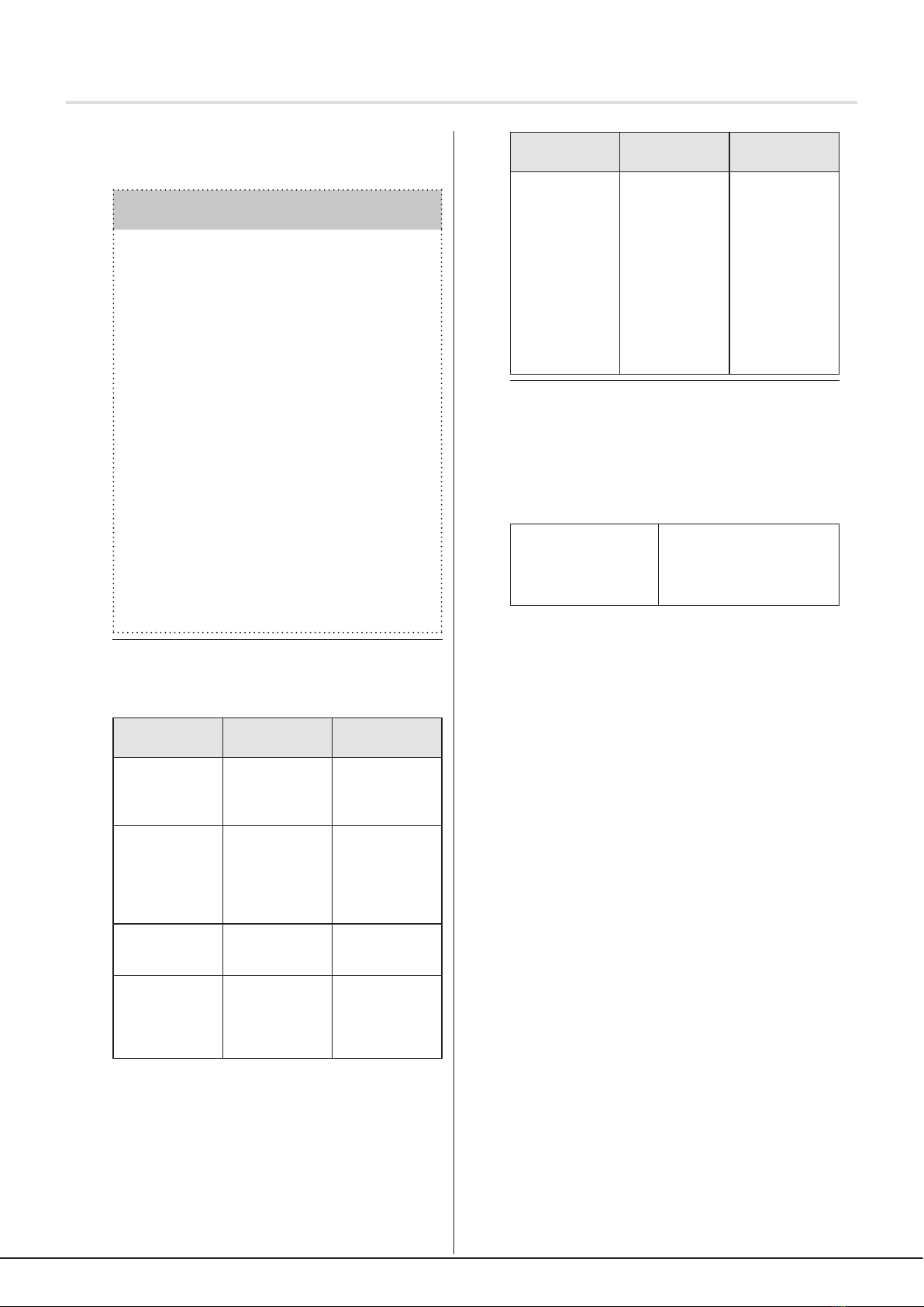
elero InDrive M30/1.6 RH Product guide

InDrive M30/1.6 RH
Actuator for Louvre Roof
138209401_EN_0621
InDrive M30/1.6 RH Actuator
1 Operating and assembly instructions
Follow these instructions for safe and proper use. Observe all
assembly instructions since incorrect assembly can lead to
serious injuries. Keep the instructions for future reference.
The German operating instructions are the original
version.
All documents in other languages are translations of the
original version.
All rights reserved in the case of patent, utility model or design
registrations.
2 General information on these instructions
The content structure is based on the life cycles of the electric
motor drive (hereinafter referred to as "the product").
The manufacturer reserves the right to make changes to the
technical data in these operating instructions. In some cases,
this technical data may dier from those of the respective
product version; however, the functional information will not
undergo signicant changes or become invalid. The current
version of the technical specications may be requested from
the manufacturer at any time. No claims may be asserted
against the manufacturer as a result of this provision.
Deviations from textual or visual statements may occur
depending on the product's technical development, features
and accessories. Deviating information for special versions will
be provided by the manufacturer in the sales documentation.
Other information shall remain unaected by these provisions.
2.1 Standards and guidelines
During construction, the fundamental health and safety
requirements were applied and provision was made for the
appropriate legislation, standards, directives and guidelines.
The safety of the product is conrmed by the declaration of
conformity (see Declaration of Conformity). All information
relating to safety in these operating instructions refers to the
laws and regulations that are currently valid in Germany. All
information in these operating instructions must be complied
with at all times and without limitation. In addition to the
safety notes in these operating instructions, the regulations
on accident prevention, environmental protection and
occupational health and safety applicable at the location
of use must be observed and adhered to. The regulations
and standards for safety assessment can be found in the
Declaration of Conformity.
Contents
1 Operating and assembly instructions 1
2 General information on these instructions 1
2.1 Standards and guidelines 1
2.2 Intended use 2
2.3 Foreseeable misuse 2
2.4 Warranty and liability 2
2.5 Customer service provided by the manufacturer 2
3 Safety 2
3.1 General safety instructions 2
3.2 Layout of safety instructions 2
4 Product description 3
4.1 Product contents 3
4.2 Accessories 3
5 Assembly 3
5.1 Mechanical fastening 4
5.2 Electrical connection 4
5.3 Connection example: InDrive M30/1.6 RH
230 V / 50 Hz 5
5.4 Parallel circuit 5
5.5 Commissioning 5
5.6 Setting the end positions and release 5
5.6.1 Release function for end positions 5
5.6.2 Release function in initial position 5
5.6.3 Release function in end position 5
5.6.4 Changing/deleting end positions and deleting the
release function 5
5.6.5 Four end position variants 6
5.6.6 Variant A: Initial position and end position freely
adjustable 6
5.6.7 Variant B: Initial position at limit stop, end position
freely adjustable 6
5.6.8 Variant C: Initial position and end position at limit
stop 6
5.6.9 Variant D: initial position freely adjustable, end
position at limit stop 7
6 Troubleshooting 7
7 Servicing 7
8 Service/manufacturer's address 7
9 Repairs 7
10 Disassembly and disposal 7
11 Conformity Declaration 8
12 Technical data and dimensions 8
12.1 InDrive M 8

3 Safety
3.1 General safety instructions
General safety instructions for use of tubular drives can be
found in the "Safety instructions" leaet supplied with each
drive (article number 138200001). These operating instructions
contain all the safety information that must be observed in
order to avoid and prevent danger when working with the
product in the individual life cycles. When all specied safety
instructions are complied with, safe operation of the device is
guaranteed.
3.2 Layout of safety instructions
The safety instructions in this document are marked using
hazard and safety symbols and are designed according to
the SAFE principle. They contain information on the type and
source of the danger, possible consequences and on avoiding
danger.
The following table denes the representation and description
of hazard levels with possible physical damage as used in
these operating instructions.
Symbol Signal
word
Meaning
DANGER Warns about an acci-
dent that will occur if the
instructions are not fol-
lowed, which can lead to
fatal, irreversible injuries
or death.
WARNING Warns about an acci-
dent that may occur if
the instructions are not
followed, which can lead
to serious, possibly fatal,
irreversible injuries or
death.
CAUTION Warns about an acci-
dent that can occur if the
instructions are not fol-
lowed, which can lead to
slight, reversible injuries.
Fig. 1 Notation for personal injuries
The table below describes the pictograms used in these
operating instructions to illustrate the hazard situation in
relation with the symbol for the hazard level.
Symbol
Meaning
Danger caused by electrical voltage,
electric shock:
This symbol indicates dangers due to
electric current.
Fig. 2 Notation for specic danger
The table below denes the representation and description
of situations used in these operating instructions for
situations in which damage can occur to the product or
indicates important facts, conditions, tips and information.
2 | EN © elero GmbH
Warranty and liability | Safety
2.2 Intended use
The product is intended to drive electrically powered sun
protection ttings, and in particular, louvre roofs.
Other applications must be agreed upon in advance with the
manufacturer, elero GmbH Antriebstechnik (see "Address").
The plant operator shall be solely responsible for any
damages arising from the improper use of this product. The
manufacturer cannot be held liable for personal or material
damages caused by misuse or procedural errors, nor by
improper operation or commissioning.
The product may only be operated by instructed and
authorised specialist personnel while observing all safety
notes.
The safe and error-free use and operational reliability of
the product are only guaranteed when it is used properly
according to the specications contained in these operating
and assembly instructions.
Use according to its intended purpose includes the observation
and compliance of all safety instructions contained in these
operating instructions as well as all valid trade Accident
Insurance regulations and valid laws on environmental
protection. Use according to its intended purpose also includes
the compliance with all prescribed operating regulations in
these operating and assembly instructions.
2.3 Foreseeable misuse
Any use that deviates from the intended use as stated by the
manufacturer, elero GmbH Antriebstechnik is deemed as
foreseeable misuse.
2.4 Warranty and liability
The General Terms and Conditions of the manufacturer, elero
GmbH Antriebstechnik, apply at all times. The conditions of
sale and delivery are included in the sales documents and
shall be presented to the plant operator upon delivery. Any
liability claims for personal or material damages are excluded
when they can be attributed to one or more of the following
causes:
• Opening the product by the customer
• Improper use of the product
• Improper installation, commissioning or operation of the
product
• Structural modications to the product without the written
consent of the manufacturer
• Operation of the product with improperly installed
connections, defective safety devices or improperly installed
safeguards
• Failure to observe the safety regulations and information
presented in these operating instructions
• Failure to observe the specied technical data
2.5 Customer service provided by the
manufacturer
In the event of a fault, the product may only be repaired by
the manufacturer. The address for sending the product to
Customer Service can be found in the "Address" section. If
you did not purchase the product directly from elero, please
contact the supplier of the product.

Symbol Signal
word
Meaning
ATTEN-
TION
This symbol warns
against possible damage
to property or equipment.
IMPORT-
ANT
This symbol indicates
important facts and states
as well as referring to fur-
ther information in these
operating and assembly
instructions. It also refers
to certain additional in-
structions, which provide
additional information or
help you to carry out a
procedure more simply.
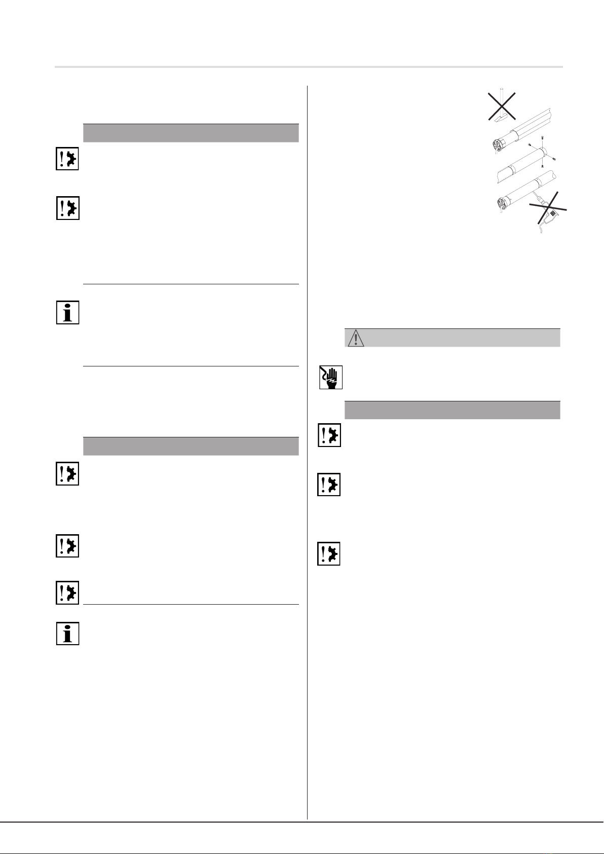
Protection class I symbol
Fig. 3 Notation for damage to property and additional
information
The following example illustrates the basic structure of a safety
note:
SIGNAL WORD
Type and source of danger
Explanation of type and source of danger
►Measures to avoid the danger
4 Product description
The InDrive M30/1.6 RH is an electromechanical tubular drive
for sun protection systems with horizontally moving slats.
During operation it executes radial movements.
Commissioning of the InDrive M30/1,6 RH with elero
assembly cable for the conguration of various functions.
Slat protection with free travel (torque limiting).
Release function for the slats
4.1 Product contents
Drive with safety instructions and operating instructions and
any additional components and accessories according to the
order conrmation or delivery note.
4.2 Accessories
Connection and assembly cable, adapter sets, motor bearing,
ProLine control units, sensors, receivers.
5 Assembly
WARNING
Important safety instructions.
Observe all assembly instructions since incorrect assembly
can lead to serious injuries.
►Commissioning of the InDrive M30/1.6 RH with elero
assembly cable for setting various functions.
►Before installation, all cables and components that are not
required and all facilities that are not needed for operation
with a power drive are to be disabled.
►The required components are: drive, connection and
assembly cable, motor bearing, adapter sets, if necessary
rigid shaft connectors, sensors, control devices, receivers.
►If components are not delivered with the drive, these can
be identied via our catalogue "Drives and control units for
intelligent building technology" in the relevant valid version.
Further details can be found on our website under "Contact
- Dealer Search" and "Contact - Partner Area".
►The rated torque and rated operating time must be suitable
for the properties of the driven part (the slats of the sun
roof).
►The coupling of the drive with the powered part is described
in the section "Mechanical fastening".
CAUTION
Risk of injuries due to hot surfaces.
The drive will heat up during operation, the drive casing can
become hot. Skin burns are possible.
►Wear personal protection equipment (protective gloves).
Triggered by a possible material fault, knocks or impact
injuries may arise due to a gear fracture, burring fracture or a
coupling defect.
►Suitable materials have been used for the engineering
design and random sample testing by means of a double
load test has been performed in accordance with DIN EN
60335-2-97.
Risk of injury due to knocks or impact triggered by motor
bearings that are incorrectly mounted or engaged. Hazard
due to insufficient stability or steadiness and accumulated
energy (gravity).
►Selection of motor bearing by torque specications.
►The drive must be protected with all the enclosed safety
devices.
►Check for correct engagement on motor bearing and the
correct screw tightening torques.
WARNING
Risk of injury due to electric current.
Risk of electric shock.
►Always have electrical work carried out by an authorised
electrician.
Risk of injury due to electric current.
Possible danger due to parts that are faulty becoming
energised.
►Electrical connection is described in the operating and
assembly instructions, including cable routing.
►The drive falls under protection class I (protective
conductor system). All housing parts of the drive capable
of conducting electricity are connected with the protective
conductor system of the xed electrical installation, which
is located at potential earth. The protective conductor
connection is designed so that, the rst time the plug is
inserted, it is connected rst and, in case of any damage,
it is disconnected last. The connecting cable is tted with
mechanical strain-relief when inserted in the drive. If the
cable is torn out, the protective conductor will be torn o last.
If, in case of a fault, a live cable comes into contact with the
housing, which is connected with the protective conductor,
a short circuit will generally arise so that the fuse itself is
triggered and de-energizes the electric circuit. No electricity
will be conducted to human beings in case of a fault. 4-core
connecting cables (4 x 0.75 mm2cross-section with black
CONINVERS plug) are used for the electrical connection with
an earthing contact that is conducted to the exterior.
CAUTION
Risk of injury due to malfunctions as a result of incorrect
assembly.
© elero GmbH EN | 3
Product description | Assembly (mechanical fastening)

Installation in prole tubes
ⒶPush drive with relevant adapter and
crown into the prole tube.
Install the motor cable so it is protected
to prevent damage from the driven
part.
ⒷSecure the counterpart support to
prevent axial movement, e.g. screw
or rivet on the idler. Secure the drive
axially in the support!
ⒸAttachtheblindtotheshaft.
The drive is fastened on the wall anchor and the blind
mounted on the shaft using the suitable motor bearings and
adapter components according to building requirements
and, depending on the type of blind, with suitable connection
elements, also provided by the system supplier.
Only operate the drive horizontally, as intended, with the
connection cable leading out from the side and away from the
slat movement area.
5.2 Electrical connection
WARNING
Faulty electrical connections constitute a fatal hazard.
Risk of electric shock.
►Prior to initial commissioning, check the PE wire is correctly
connected.
ATTENTION
Damage to the InDrive M30/1.6 RH due to incorrect electrical
connection.
►Prior to initial commissioning, check the PE wire is correctly
connected.
Damage to or destruction of the InDrive M30/1.6 RH due to
the penetration of moisture.
►For devices with protection class IP 44, the customer-side
connection of the cable ends or plugs (cable feed-through)
can also be implemented according to protection class
IP 44.
Damage to or destruction of the InDrive M30/1.6 RH for
variants with 230 V 1 AC due to incorrect activation.
►Switches for drives that are set to OFF by default (dead-
man's switches) are to be installed within visible range of the
InDrive M30/1.6 RH, but away from moving parts and at a
height of more than 1.5 m.
4 | EN © elero GmbH
Assembly (electrical connection)
Drive is overwound and may destroy parts of the application.
►For safe operation, the end positions must be set/taught in.
►Manufacturer training is available for specialist companies.
ATTENTION
Power failures, breaking of machine parts and other
malfunctions.
►For safe operation, assembly must be correct and the end
positions must be congured upon commissioning.
Damage to InDrive M30/1.6 RH due to the penetration of
moisture.
►On devices with protection class IP 44, the ends of all
cables or plugs will need to be protected from ingress of
moisture. This measure must be implemented immediately
after removing the InDrive M30/1.6 RH from the original
packaging.
►The drive must be installed so that it cannot get wet.
Important
In its delivery state (factory setting), the InDrive M30/1.6 RH
will be in commissioning mode.
►The end positions will need to be congured
(see section 5.6).
5.1 Mechanical fastening
Important preliminary consideration:
The working area around the installed drive is usually very
small. For this reason, obtain an overview of how the electrical
connection has been implemented prior to the mechanical
installation (see section 5.2) and make the necessary changes
beforehand.
ATTENTION
Crushing or tension will damage the electrical cables.
►Install all electrical cabling so that it is not subject to any
crushing or tensile load
►Observe the bending radii of cables (at minimum 50 mm).
►Route connecting cables in a downward loop to prevent
water running into the drive.
Damage to the drive due to the effect of impact forces.
►Slide the drive into the shaft. Never knock the drive in or use
force!
►Take care not to drop the drive!
Damage or destruction to the drive by drilling.
►Never drill the drive!
Important
Only secure the InDrive M30/1.6 RH using the fastening
elements provided for this purpose.
Fixed installed control devices need to be attached so they are
visible.
• The prole tube must have sucient clearance from the
motor tube.
• Make sure there is sucient axial play (1 - 2 mm)

5.3 Connection example: InDrive M30/1.6 RH
230 V / 50 Hz
102
reseau electrique
L
N
PE
230V/50Hz
vert-jaune
brun
noir
bleu
de volet
M
1~
102
rete
L
N
PE
230V/50Hz
verde/giallo
marrone
nero
blu
M
1~
102
Netz
L
N
PE
230V/50Hz
grün/gelb
braun
schwarz
blau
oder -taster
M
1~
102
power grid
L
N
PE
230V/50Hz
green/Yellow
brown
black
blue
junction box
M
1~
boiter de scatola di
derivatione
3
2
1
3
2
1
Fig. 4 Connection diagram InDrive M30/1.6 RH 230 V/
50 Hz and cable assignment when using
Hirschmann plug connection STAS-3
Important
The motor controls in the up/down direction must be locked
against each other.
A reversing delay of at least 0.5 seconds must be ensured.
5.4 Parallel circuit
Important
You can connect several InDrive M30/1.6 RH in parallel.
Please note the maximum switching capacity of the control
unit.
5.5 Commissioning
Important
The drive is in commissioning mode when delivered.
►The end positions must be congured using the elero
assembly cable
►The assembly cable may only be connected to
commission the drive and for adjustment operations
%ODX1HXWUDOOHLWHU
6FKZDU]
%UDXQ
*UQJHOE
HOHUR
HOHUR
%ODX1HXWUDOOHLWHU
6FKZDU]
%UDXQ
*UQJHOE
Fig. 5 Connection for assembly cable
►Switch on mains.
►You can now congure the end positions using the elero
assembly cable.
5.6 Setting the end positions and release
Important preliminary consideration:
Decide on a specic release function before actually setting
the end positions (dierent combination options as per the
following designs).
This saves you unnecessary conguration work!
Press the adjustment keys until the drive signals the switch
to programming mode by means of a short automatic stop.
You can now set the end positions. Programming mode is
nished once both end positions have been set.
5.6.1 Release function for end positions
If an end position was taught in at a limit stop, a release can
also be enabled for the slats.
Important
The release function (for variants B to D) is activated in
a single step when programming the end positions (see
chapters 5.6.7 to 5.6.9)!
5.6.2 Release function in initial position
For variant B (see chapter 5.6.7) and variant C
(see chapter 5.6.8):
Activate release function in initial position
1 Using the assembly cable while holding down the
[UP ▲] button from instruction ①(chapters 5.6.7 and
5.6.8), press the [DOWN ▼] button (simultaneously)
and hold down both buttons until the slats stop.
The release function in initial position is activated.
5.6.3 Release function in end position
For variant C (see chapter 5.6.8) and variant D
(see chapter 5.6.9):
Activate release function in end position
1 Using the assembly cable while holding down the
[DOWN ▼] from instruction ①(chapters 5.6.8 and
5.6.9), press the [UP ▲] button (simultaneously) and
hold down both buttons until the slats stop.
The release function in end position is activated.
5.6.4 Changing/deleting end positions and
deleting the release function
It is not possible to change or delete individual end
positions. This is always done in pairs (initial position and
end position at the same time).
When the end positions are deleted, the setting for the
optional release function will also be lost.
Important
The protection for the slats is only adapted to the slats after
a complete, uninterrupted extension and retraction (cycle).
Changing/deleting the end positions
1 Starting from a central slat position, use the assembly
cable to simultaneously press both direction buttons
[UP ▲] + [DOWN ▼] and hold them down until the
slats briey move up and down.
The end position settings have been deleted.
The end positions can be reset.
© elero GmbH EN | 5
Commissioning | Conguration of end positions and release

Variant B: Initial position at limit stop, end position
freely adjustable
② Press the [DOWN/CLOSE ▼] button until the drive
stops automatically.
The initial position is set.
Optional: Activate the release function for the initial
position: See chapter 5.6.2
③ Press the [DOWN/CLOSE ▼] button again until the
slats have reached the desired end position.
The drive begins to travel, briey stops and travels
further (for as long as the button remains pressed).
You can make corrections using the [UP ▲] and
[DOWN/CLOSE ▼] buttons.
④ Press the [UP ▲] button until the drive stops auto-
matically.
Adjustment of the variant B end positions is complete.
Fig. 8 End positions variant B:
5.6.8 Variant C: Initial position and end position at
limit stop
Variant C: Initial position and end position at limit
stop
① Starting from a central slat position, press the
[UP ▲] button with the assembly cable until the
slats have reached the desired initial position (travel
to limit stop).
The drive begins to travel, briey stops, and then
travels further (for as long as the [UP ▲ ] button
remains pressed).
The drive switches o automatically when it reaches
the initial position.
② Press the [DOWN/CLOSE ▼] button until the drive
stops automatically.
The initial position is set.
Optional: Activate the release function for the initial
position: See chapter 5.6.2
③ Press the [DOWN/CLOSE ▼] button again until the
slats have reached the desired end position (travel
to limit stop).
The drive begins to travel, briey stops, and
then travels further (for as long as the [DOWN/
CLOSE ▼] button remains pressed).
The drive switches o automatically when it reaches
the end position.
④ Press the [UP ▲]button until the drive stops auto-
matically.
The end position is set.
Optional:Activate the release function for the end
position: See chapter 5.6.3
Adjustment of the variant C end positions is complete.
Fig. 9 End positions variant C:
6 | EN © elero GmbH
Setting the end positions and release
5.6.5 Four end position variants
Four dierent end position settings are possible. These
can be selected as appropriate, according to the technical
requirements of the slats.
End positions (4 variants)
A Initial position and end position freely adjustable
BInitial position at limit stop, end position freely ad-
justable
C Initial position and end position at limit stop
DInitial position at limit stop, end position freely ad-
justable
Fig. 6 Variants of the end positions for the InDrive M
5.6.6 Variant A: Initial position and end position
freely adjustable
Variant A:
Initial position and end position freely adjustable
① Starting from a central slat position, press the
[UP▲] button with the assembly cable until the slats
have reached the desired initial position.
The drive begins to travel, briey stops, and then
travels further (for as long as the [UP ▲ ] button
remains pressed).
You can make corrections using the [UP ▲] and
[DOWN/CLOSE ▼] buttons.
② Press the [DOWN/CLOSE ▼] button until the drive
stops automatically.
The initial position is set.
③ Press the [DOWN/CLOSE▼]button again until the
slats have reached the desired end position.
The drive begins to travel, briey stops, and
then travels further (for as long as the [DOWN/
CLOSE ▼] button remains pressed).
You can make corrections using the [UP ▲] and
[DOWN/CLOSE ▼] buttons.
④ Press the [UP ▲] button until the drive stops auto-
matically.
The end position is set.
Adjustment of the variant A end positions is complete.
Fig. 7 End positions variant A:
5.6.7 Variant B: Initial position at limit stop, end
position freely adjustable
Variant B: Initial position at limit stop, end position
freely adjustable
① Starting from a central slat position, press the [UP
▲] button with the assembly cable until the slats
have reached the desired initial position (travel to
upper limit stop).
The drive begins to travel, briey stops, and then
travels further (for as long as the [UP ▲ ] button
remains pressed).
The drive switches o automatically when it reaches
the initial position.

5.6.9 Variant D: initial position freely adjustable,
end position at limit stop
Variant D: initial position freely adjustable, end
position at limit stop
① Starting from a central slat position, press the
[UP▲] button with the assembly cable until the slats
have reached the desired initial position.
The drive begins to travel, briey stops and travels
further (for as long as the button remains pressed).
You can make corrections using the [UP ▲] and
[DOWN/CLOSE ▼] buttons.
② Press the [DOWN/CLOSE ▼] button until the drive
stops automatically.
The initial position is set.
③ Press the [DOWN/CLOSE ▼] button again until the
slats have reached the desired end position (travel
to limit stop).
The drive begins to travel, briey stops, and
then travels further (for as long as the [DOWN/
CLOSE ▼] button remains pressed).
The drive switches o automatically when it reaches
the end position.
④ Press the [UP ▲] button until the drive stops auto-
matically.
The end position is set.
Optional: Activate the release function for the end
position: See chapter 5.6.3
Adjustment of the variant D end positions is complete.
Fig. 10 End positions variant D:
6 Troubleshooting
Problem / Error Possible cause Remedial
action
• Drive stops
during travel
• End positions
are not set
• Drive is in
setting mode
• Congure end
positions
• Drive stops
after short time
• End position
has been pro-
grammed
• Sti slats
• Set end po-
sition
• Check the
ease of move-
ment of the
slats
• Drive runs only
in one direction
• Faulty connec-
tion
• Check connec-
tion
• Drive does not
react
• No power
supply
• Temperature
limiter has
triggered
• Check mains
voltage
• Allow drive to
cool down
Problem / Error Possible cause Remedial
action
• End positions
cannot be
taught into the
drive
• Random travel
• Travel to end
position or limit
stop too short
• Delete end
positions,
re-programme
end positions
• Drive must
move, stop
briey and
continue its
travel (as long
as a button
on the assem-
bly cable is
pressed).
Fig. 11 Troubleshooting for the InDrive M30/1.6 RH
7 Servicing
The InDrive M30/1.6 RH requires no maintenance.
8 Service/manufacturer's address
elero GmbH
Drive technology
Maybachstr. 30
73278 Schlierbach
Deutschland / Germany
Tel: +49 7021 9539-0
Fax: +49 7021 9539-212
www.elero.com
Please visit our website if you require a contact partner
outside Germany.
9 Repairs
Please contact your specialist if you have any questions.
Please always provide the following information:
• Item number and designation on the type plate
• Type of fault
• Accompanying conditions
• Your own theories regarding the cause of the problem
10 Disassembly and disposal
After unpacking, dispose of the packaging in accordance
with the valid regulations.
Dispose of the product in accordance with the relevant
regulations when you no longer need it.
Environmental information
No superuous packaging materials have been used. The
packaging can be easily separated into three material
types: cardboard (box), polystyrene (padding) and
polyethylene (bag, protective foam).
The device is made of materials that can be reused if
dismantled by a specialist company. Please note the local
regulations on disposal of packaging materials and old
appliances.
On disassembly, additional dangers must be reckoned with,
which do not occur during operation.
Before disassembling the drive the system is to be
mechanically secured. The drive must not be forcibly
disconnected from the system.
© elero GmbH EN | 7
Setting the end positions and release | Troubleshooting

Dismantling and disposal | Technical data and dimensions
WARNING
Risk of injury due to electric current.
Risk of electric shock.
►Separate power supply cables physically and discharge
any energy accumulators still charged. After switching o
the device, wait at least 5 minutes so that the motor can
cool down and the voltage can be discharged from the
capacitors.
►During disassembly work above head height, use
suitable, inspected and structurally stable climbing aids.
►Work on the electrics may only be performed by
personnel described in the section "Safety notes on
electrical installation".
Removal for scrap
The international, national and regional laws and
regulations prevailing at the time of scrapping the product
must be observed.
Ensure that materials and components are recycled,
dismantled and separated properly in addition to observing
the environmental and health hazards relating to recycling
and disposal.
CAUTION
Environmental damage in case of incorrect disposal
►Electrical scrap and electronic components must be
handled as special waste and may only be disposed of by
approved specialist companies.
►Groups of materials such as various types of plastics and
metals must be separated before recycling/disposal.
Disposal of electrical and electronic components
The disposal and recycling of electrical and electronic
components must be carried out in accordance with the
relevant laws and national regulations.
11 Conformity Declaration
elero GmbH hereby declares that this product conforms
with the applicable directives. For the full declaration of
conformity, visit www.elero.com
12 Technical data and dimensions
The technical data specied is subject to tolerance factors
(according to applicable standards) and refer to an ambient
temperature of 20 °C.
12.1 InDrive M
InDrive M30/1.6 RH
Rated torque [Nm] 30
Rated speed [rpm] 1.6
Rated voltage [V] 1 ~ 230
Rated frequency [Hz] 50
Noiseless soft brake ■
Rated current [A] 0.52
Rated power consumption
[W] 118
Shaft diameter [mm] 50
Degree of protection
(IP-Code) 44
Limit switch range (revolu-
tions) 40
Operating time (min. S2) 4
Length C [mm] 469
Length D [mm] 452
Length E [mm] 12
Weight [kg] 1.9
Operating ambient tempera-
ture [°C] -20 to 70
Protection class I
■
Conformity , -, -
Item No. 38 147.0001
33
D
C
E
55
C
D
E
E
45O
55
C
D
33
33
C
D
33
E
45O45O
45O
C
D
33
45O
O57,5
E
C
D
33
45O
O57,5
E
29
O49,5
O49,5
C
D
45O
E33
O60,4
RolBasic Soprofen
Stator FE C D E Motorrohr
Rol/Sun/Vari
M6-k 381 364 ele ro=14 339
M10-k 391 374 RH=12 349
M6 446 429 SH=19 404
M10 466 449 424
M7/23 (120V )//M10/17 (120V) 486 469 444
M30 516 499 474
M20 526 509 484
M40/M50 546 529 504
RolTop M1,8/138 RH Ne her 384493401 120 556 539 514
RolTop M1,8/138-868 RH Ne her 384403406 120
RolBasi c M6 Soprofen 643011902 481 464 12,6 438,5
RolBasi c M10 Soprofen 643211902 481 464 12,6 438,5
RolBasi c M20 Soprofen 643311902 506 489 12,6 464
D= C-17mm (halbe Kupplung)
Baugröße Typ
We reserve the right to make technical changes
elero GmbH
Antriebstechnik
Maybachstr. 30
73278 Schlierbach
www.elero.com
Table of contents
Other elero Controllers manuals

elero
elero Insolis 4 User manual

elero
elero Compakt User manual

elero
elero MemoTec-868 User manual

elero
elero Vario 1 User manual

elero
elero ExitSafe 28 388.0001 User manual

elero
elero BoxControl Compact User manual

elero
elero Herkules 1 User manual

elero
elero AstroTec 28 060.0001 User manual

elero
elero Combio-915 JA User manual

elero
elero VarioTec-868 DC User manual
Popular Controllers manuals by other brands

Galil
Galil DMC-1510 user manual

OPTO 22
OPTO 22 LCSX-PLUS installation guide

Ascon tecnologic
Ascon tecnologic TLK41 operating instructions

Bosch
Bosch Rexroth ACU Series Instructions & installation

Vx Aviation
Vx Aviation MakerPlane M-PWR-2 Series manual

Allen-Bradley
Allen-Bradley PowerFlex 4 Original instructions