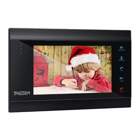
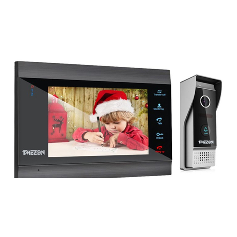
TMEZON MZ-VDP-HD739W User manual

7'' Indoor Monitor
OPERATION INSTRUCTION
4-Wire Video Door Phone
User Manual
* If there is any doubt or disputable regarding information in this manual, you can
call our company for clarification.
* There maybe some difference between the description provided here and the
actual devices, as our products are constantly developing and upgrading. We
apologize if this manual does not contain all of the latest updates. Thanks
Statement
Official Website: http://www.tmezon.com
Manufacturer: Zhuhai Tmezon Technology Co.,Limited
Address: No.6.Pingbei 2nd.Rd, NANPING Technology Area,
Zhuhai City,Guangdong,China
If you have any problem during the installation or the usage,
please send email to our support team, we will help you
solve the problem ASAP.
Support email: support@tmezon.com

LIMITATION OF LIABILITY
This users' manual is supplied 'as is', with no warranties, be it expressed or implied, including,
but not limited to, the implied warranties of merchantability, suitability for any exact purpose, or
non-infringement of any third party's rights.
This publication may include technical inaccuracies or typos. The manufacturer holds the right
to introduce any changes to the information contained herein, for any purpose, including but not
limited to, improvements of the publications and/or related to the product, at any time, without
prior notice.
※
※
DISCLAIMER OF WARRANTY
The supplier shall not be liable to any party or any person, except for replacement or reasonable
maintenance of this product, for the cases, included but not limited to the following:
Any damage or loss, including but not limited to: direct/indirect, consequential, special,
exemplary, arising out of or related to the product;
Inappropriate use or negligence of the user in operation of the product, resulting in personal
injury or any damage;
Unauthorized disassembly, repair or modification of the product by the user;
Any problems or consequential inconvenience, loss or damage, caused by connecting this
product to devices of the third parties;
Any claim or action for damages, brought by any photogenic subject, be it a person or
organization, due to violation of privacy whereby the pictures taken by the device and/or saved
data become public or are used for the purposes other than intended.
※
※
※
※
※
SAFETY INSTRUCTIONS
Read these instructions and keep them in a safe place for future reference.
Please refer all work related to the installation of this product to qualified service personnel or
system technician.
Do not operate the appliance beyond its specified temperature, humidity or power source
ratings.
Securely install the devices on vertical surfaces (solid walls/doors) not prone to vibration or
impact.
Install the devices away from heat sources such as radiators, heat registers and stoves.
Installation of the terminal near consumer electronics devices, e.g. stereo receiver/amplifiers
and televisions, is permitted as long as the air surrounding the terminal does not exceed the
above mentioned temperature range.
Handle the appliance with care. Do not strike or shake, as this may damage the device.
The doorbell/camera units should be fitted with an approved weather shield if the chosen
position is in direct sunlight, or in contact with rain, snow or irrigation sprinkler systems.
Do not use strong or abrasive detergents when cleaning the appliance body. When the dirt is
hard to remove, use a mild detergent and wipe gently.
Do not overload outlets and extension cords as this may result in a risk of fire or electric shock.
Distributing, copying, disassembling, reverse compiling, reverse engineering, and also
exporting in violation of export laws of the software provided with this product, is expressly
prohibited.
※
※
※
※
※
※
※
※
※
CARING FOR THE ENVIRONMENT BY RECYCLING
When you see this symbol on a product, do not dispose of the
product with residential or commercial waste.
Recycling your electrical equipment
Please do not dispose of this product with your residential or commercial waste. Some countries or
regions, such as the European Union, have set up systems to collect and recycle electrical and
electronic waste items. Contact your local authorities for information about practices established for
your region.
COPYRIGHT STATEMENT
All rights reserved. No part of this publication may be reproduced in any form or by any means,
transcribed, translated into any language or computer language, transformed in any other way,
stored in a retrieval system, or transmitted in any form or by any means, electronic, mechanical,
recording, photocopying or otherwise, without the prior written permission of the owner.
12
This equipment has been tested and found to comply with the limits for a Class B digital
device, pursuant to Part 15 of the FCC Rules. These limits are designed to provide reasonable
protection against harmful interference in a residential installation. This equipment generates
uses and can radiate radio frequency energy and, if not installed and used in accordance with
the instructions, may cause harmful interference to radio communications. However, there is
no guarantee that interference will not occur in a particular installation. If this equipment does
cause harmful interference to radio or television reception, which can be determined by turning
the equipment off and on, the user is encouraged to try to correct the interference by one or
more of the following measures:
-- Reorient or relocate the receiving antenna.
-- Increase the separation between the equipment and receiver.
-- Connect the equipment into an outlet on a circuit different from that to which the receiver is
connected.
-- Consult the dealer or an experienced radio/TV technician for help.
Changes or modifications not expressly approved by the party responsible for compliance
could void the user's authority to operate the equipment.
FCC Statement

800mA
External switching power
supply(DC12V)
7'' TFT LCD Screen
1024(H)*600(V)
64GB
400mA
External switching power supply DC 12V--------------------------------1pcs
Monitoring
Unlock
Talk
Hang up
1
2
236mm
TF
142mm
14mm
Monitoring
Unlock
Talk
Hang up
1
2
5pcs
Monitoring
Unlock
Talk
Hang up
1
2
Wiring connection according to the following to avoid interference:
Power+ Video
Audio GND GND Audio
Power+ Video
The power supplies for electric lock , CCTV cameras and extension cables are not included in
the package, user can purchase according to actual requirement.
The indoor monitor is with an external switching power supply DC 12V. If you don't want to
use the external power supply, please use 2 pin cable and DIN rail power supply to extend
the power cable to your home power supply center and hide the wire in the wall.
If over 3m, we suggest you to use the thicker power cable and higher ampere power supply,
or the monitor and doorbell can not get enough power, which will affect the conversation
and unlocking.
Note On Wiring Connection

Unshielded wiring cable:
AU DIO
VI DE O
GND
DC 12 V
AU DIO
VI DE O
GND
DC12V
Please note the silk printing marked on PCB in order to avoid incorrect connecting.
The wiring connection requirement(The actual effect and the quality of wire rod has
the very big relations):
2. Effective distance from the outdoor camera to furthest indoor monitor:
2
Transmission ≤30m (4x0.4mm )
2
Transmission ≤60m (4x0.65mm )
AU DIO
VI DE O
GN D
DC 12 V
Shielded wiring cable:
Shield Shield
AU DIO
VI DE O
GN D
DC12V
3. If you want to extend the distance over 60m, you'd better to choose a thick copper core
cable, or a shielded wiring cable, or a 3-core ordinary unshielded wire + a 75-3 video wire.
Connect the shield terminal with the GND.
AU DIO
VIDEO
GN D
DC 12 V
AUDIO
VI DE O
GND
DC 12 V
3-core unshielded wiring cable
75-3 video wiring cable
Shield
1. 4-Core ordinary unshielded and shielded wiring cable;
3-core unshielded wiring cable+75-3 video wiring cable:
Connect the shield of the 75-3 video wiring cable with the GND of the 3-core unshielded
wiring cable.
4.If user wants to use CAT5 or CAT6 network cable, effective distance from the outdoor camera
to the furthest indoor monitor will be limited. For unshielded network cable, the distance will be
up to 20m. For shielded network cable, the distance will be up to 40m. So CAT5 or CAT6
network cable is not recommended.
CAT5 or CAT6 network cable consists of 4 pairs of twisted pairs(8 wires), here one pair of
twisted pair will be used as one cable.
Green&White+Green, Brown&White+Brown, Orange&White+Orange, Blue&White+Blue.
Unshielded network cable:
DC 12 V
AUDIO
VIDEO
GND
DC 12 V
AUDIO
GN D
VI DE O
Shielded network cable:
Connect the shield of the network cable with the GND.
Shield
DC 12 V
AUDIO
GN D
VI DE O
DC 12 V
AUDIO
GN D
VI DE O
Shield
When the distance from the outdoor doorbell to the indoor monitor is too far, maybe
over 50m or 60m, please make sure that the input voltage to the outdoor doorbell
must reach 11v.
56

WIRING DIAGRAM
4C
4C
4C
DOOR1
(720P/1080P/TVI/CVI/CVBS)
DOOR2
(720P/1080P/TVI/CVI/CVBS)
4C
4C
CAM1
(720P/1080P/TVI/CVI/CVBS)
CAM2
(720P/1080P/TVI/CVI/CVBS)
ALARM
ALARM
Master
(AHD Monitor)
Slave
DOOR2
78
Slave
Slave
DESCRIPTION ON INDOOR UNIT
Users can connect up to two AHD(720P/1080P) / TVI / CVI / CVBS definition outdoor doorbells
& two AHD(720P/1080P) / TVI / CVI / CVBS definition analog cameras simultaneously, and
three extension indoor monitors one by one to the corresponding interfaces by their own’s
requirement according to the following wiring diagram.
Note: 1. The CCTV cameras must use an external power supply.
2. AHD/TVI/CVI/CVBS definition cameras can be mixed connected.
3. When mixed resolution cameras are connected to the main monitor, suggest that
slave monitors connected to be AHD(720P or 1080P). If connect a standard
definition slave monitor, can only view CVBS camera’s image on the slave.
4. All the cameras must be connected to the monitor before the monitor power on.
Monitoring
Unlock
Talk
Hang up
1
2
Monitoring
Unlock
Talk
Hang up
1
2
Monitoring
Unlock
Talk
Hang up
1
2
Monitoring
Unlock
Talk
Hang up
1
2
Monitoring
Unlock
Talk
Hang up
1
2
1
2
3
5
49
6
7
8
10
11
13
TF
12
12V
POWER
External switching power
supply DC 12V
External switching
power supply
DC 12V

910
VISITOR CALL
Standby mode
The Visitor press
the call button on
outdoor camera 1
A continuous ring
tone is heard
inside and outside
The visitor’s image
automatically displayed on
the screen
Press the “Talk”
button on indoor
monitor
Stop ringing
Start conversation
with outdoor camera
The conversation
duration is 120s
at a time
Press the unlock
button on indoor
monitor
The Visitor press
the call button on
outdoor camera 2
NOTICE:
If both call button on two outdoor camera are pressed at approximate
to the same time, the preference will be given to the outdoor camera
which call button was pressed first, unless the call button is pressed
again after the indoor monitor go into standby mode, please be aware
of that there is no indication on second outdoor camera .
NOTICE:
The indoor unit will automatically go into standby mode if you are not
at home or have not reached the indoor unit in 60s.
End
release the
door lock
OPERATION INTRODUCTION
Press the “Hang up”
button on indoor monitor.
Both the visitor's voice and image will not be switched off within 20s of time span when the
unlock button is pressed, this individualized function allow you to make sure whether the
visitor already come in.
For the models with TF card, when the doorbell record for the video mode: From the start of
a call, the whole process will be recording. When the doorbell record for the snapshot mode:
if a visitor press the call button on the outdoor camera, the first picture will be captured.
In the monitoring mode, you can press the button “ ” to conversation and press the button
“ ” to unlock.
Hear the sound from outdoor doorbell.
Speaker
TF card interface, support up to 64GB card for recording and
capturing photographs. Recoding files and snapshot files will be
stored in the TF card. And suggest that it’s better to use a TF card
more than class 10 onto the device.
TF card slot
13
12
TFT display View visitor’s image displayed on the TFT screen.
Microphone Transmit the voice to outdoor camera.
Name Descriptions
Power LED, the power indicator of the indoor monitor.
The door 1 state lights, to door 1 working when the LED is on.
8
9
10
11
1
2
The door 2 state lights, to door 2 working when the LED is on.
1. Transfer call, during conversation with the doorbell, press this
button to intercom call or transfer calls to another indoor monitor.
2. Internal call, when all the indoor monitors are in standby mode,
press this button to intercom call to another indoor monitor.
3. On sub-menus, press this button to switch the menu pages.
4. Press this button to confirm after adjusting parameter values.
1. Unlock, release the door lock.
2. During playback video record, press this button to delete the current
video file. During playback pictures, press this button to delete the
current picture file.
3. On video record files list and snapshot files list, press this button
to delete all the files.
Unlock
Monitoring
Setting
1. Monitoring, press the button to watch the outdoor bell and CCTV
camera images.
2. On files list interface, press this button to the previous page.
3. During playback video record, press this button to pause/play.
1. Talk, press this button to activate conversation mode.
2. On files list interface, press this button to the next page.
Talk
Transfer call
Hang up
1. Hang up, press this button to end conversation mode.
2. Press this button to return to previous menu or cancel the
selection.
1. In standby mode, press the button “ ” once to access the main
menu.
2. On main menu settings, scroll the button “ ” to upwards or
downwards to move the cursor, then press the button “ ” to enter
sub-menu interface.
3. In monitoring mode, press this button to bring up “Brightness,
contrast, Hue” menu options, scroll the button “ ” upwards or
downwards to adjust values.
4. In intercom mode, press this button to bring up the volume order,
scroll the button “ ” upwards/downwards to increase/decrease
the volume.
5. In calling mode, press this button to bring up the ring order, and
scroll the button “ ” upwards/downwards to increase/decrease
the ring volume.
Talk
Unlock
Talk
Unlock

11 12
14
Option in the settings on the menu: DOOR1, CAM1, DOOR2, CAM2 operating mode (open or closed)
Standby Mode
Press the “Talk” button
Start conversation
with outdoor camera
NOTICE:
Show CAM1
image
Show DOOR1
image
Show DOOR2
image
Show CAM2
image
Close LCD
Each monitoring time is 60S
MONITORING
If you are using only one outdoor camera in monitoring mode, you can also end the
monitoring mode by pressing the monitoring button again(Must be Close CAM1;
DOOR2; CAM2 in the menu option).
If you use two indoor units, you can also simultaneously in other indoor unit starts
monitoring mode, the same images are displayed on the screen of the different
indoor unit.
If the indoor unit is underway in monitoring mode, during this time a visitor press the
call button on either of outdoor unit, the monitoring mode will be switched off, the
just visitor’s image will appear on its screen and continuous ringing will be heard. If
you are using the indoor unit with hands-free, you can press the talk button to
reactivate conversation with the visitor.
If a conversation with an outdoor camera is underway in calling mode, during
this time a visitor press the call button on another outdoor camera, a beep sounds
from the indoor monitor and the doorbell’s icon will display on the screen for about
3 seconds.
Internal communication function requires at least two indoor and one outdoor units to be connected.
Outdoor camera call indoor
monitor and conversation
is underway
Press the “Transfer call”
button to activate the
function of call transfer
to other extension
A continuous ring
tone is heard
NOTICE:
When you are transferring a call to other extension, the original
conversation indoor unit will return to standby mode, and the
indoor unit which the call is being transferred will also sound a
continuous ring tone and the video image will appear on its
screen.
Press the “talk”
button on any of
indoor units
At least 2 indoor units are required.
Standby Mode
Press the “Transfer
Call” button
Press the “Talk”
button on any of
indoor units
Start conversation
among indoor units.
Press the “Hang
up” button End
NOTICE:
In internal communication mode, if a visitor press the call
button on either of outdoor unit, the internal communication
mode will be switched off. The just visitor’s image will appear
on its screen and continuous ringing will be heard, you can
press the talk button to reactivate conversation with the
visitor.
CALL TRANSFER TO OTHER EXTENSION
INTERNAL COMMUNICATION AMONG INDOOR UNITS
A continuous ring
tone is heard
Monitoring Monitoring Monitoring Monitoring Monitoring
Talk
Unlock
Press the “unlock”
button, the electric
lock will be opened.
Press the “Hang
up” button to
end the call.
Talk
Talking
with visitor
Unlock
The Electric
lock can
be opened
End the call
and return to
standby mode.
Hang up
Talk
Hang up

13 14
MENU OPERATIONS
1. Set System Parameters
On main menu move the cursor to “System” option, and press “ ” to enter the “System”
menu. System setup includes: Settings, Video setting and system. Press “ ” to switch
menu pages. Press “ ” to return to previous.
NOTICE
When the screen saver function is disabled, if users don’t do any operate or enter any interface about
the indoor monitor, the indoor device will be into standby mode after 1 minute automatically. The
back-light of each button will be on when user presses any button or some visitor calls on the outdoor
doorbell. If the indoor monitor is in standby mode, the back-light of each button will be off if user
doesn’t do any operate on the device in 10 seconds.
In standby mode, press the button “ ” to access the main menu interface, shows the main interface
as shown below. On main menu settings, scroll the button “ ” upwards or downwards to move the
cursor to select sub-menu, the selected icon will be highlighted, then press the button “ ” again to
enter sub-menu interface. On sub-menu settings, scroll the button “ ” upwards or downwards to
select menu options, and press the button “ ” to toggle menu page or to confirm after modifying
parameters. Press the button “ ” to cancel and exit current menu interface.
1.1 System-Settings
On settings menu, to set up Screen saver and Time Setting.
[ ]: Press the “ ” button to switch menu pages.
[ ]: Press the “ ” button to return to previous.
[Screen saver]: Options include “Disable”, “1min”, “3min”, “5min”, “10min” and “Never close”. For
example, “1min” means when the device is in standby mode, the system date and time will display on
the screen for about 1 minute. “Disable” indicates that the system date and time won’t be displayed on
the screen. “Never close” indicates that the system date and time will always display on the screen.
[ ]: After choosing the menu option, press the “ ” button to confirm.
[ ]: Press the “ ” button to cancel and return to the previous.
[Language]: Use this field to change the language of the device menu text and the
on-screen display.
[Time Setting]: Use this field to set up system date and time.
Press the “ ” button to move the cursor, scroll the “ ” button upwards or downwards to
modify the parameters. After modifying the parameters, press the “ ” button to confirm
and exit, press the “ ” button to cancel and exit.
[ ]: After modifying the parameters, press the “ ” button to confirm and exit.
[ ]: Press the “ ” button to cancel and return to the previous.
1.2 System-Video setting
On settings menu, press the “ ” button to enter “Video setting”.
Scroll the “ ” button to move the cursor, press the “ ” button to select menu option,
press the “ ” button to confirm and exit, press the “ ” button to cancel and exit.
[Auto check]: “On” indicates that the indoor monitor will automatically check the video
input format when the monitor starts up. Support AHD(720P/1080P), TVI, CVI and
CVBS. When it set as “Off”, user can set up video setting parameters manually. Choose
“Door1/Door2/CAM1/CAM2” to configure “Transfer mode, Image size and Video mode”.
System Ring Mode
Alarm Motion detect Files
System Ring Mode
Alarm Motion detect Files
Screen saver
Disable
1 minute
3 minute
5 minute
10 minute
Never close
Modify ( ) ( )
Time Setting
Confirm Cancel
( ) ( )
2019 / 07 / 01 10 : 55 : 23
Settings
Screen saver Disable
Language
( ) ( )
Time Setting

[Transfer mode]: Options include AHD, TVI, CVI and CVBS.
[Image size]: 720P and 1080P can be selected.
[Video format]: Options include PAL and NTSC.
[ ]: Press the “ ” button to switch menu pages.
[ ]: Press the “ ” button to return to previous.
Video Setting
Door1
Door2
CAM1
CAM2
Auto check On
( ) ( )
Confirm Cancel
Transfer mode AHD TVI CVI CVBS
Image size 720P 1080P
Video format PAL NTSC
Door1 Setting
( ) ( )
On “Door Setting” or “Camera Setting” interface, press the “ ” button to move the cursor,
scroll the “ ” button upwards or downwards to modify the parameters. After modifying the
parameters, press the “ ” button to confirm and exit, press the “ ” button to cancel and
exit.
1.3 System-System
On settings menu, press the “ ” button to switch menu pages to enter system menu
interface.
Scroll the “ ” button upwards or downwards to move the cursor, press the “ ” button to
enter the menu interface.
[ ]: Press the “ ” button to confirm.
[ ]: Press the “ ” button to cancel to return.
[SD card capacity]: To view the SD card usage state.
[Software Version]: To view the device software version.
[Format SD]: To format the SD card. For the first time please format the SD card inserted
first before using. When format a TF card on the monitor, it will auto-creat five folds which
named as “FRAME”, “PHOTO”, “VIDEO”, “BACKUP” and “RING”. “FRAME” is used to
store E-Photos, “Photo” is used to store snapshot files, “VIDEO” is used to store video
recordings, “BACKUP” is used to store the pictures backing up from the built-in storage,
and “RING” is used to store Mp3 ring tones.
Notice: Suggest use a SD card more than Class 10 onto the monitor. And the SD
card capacity can be up to 64GB.
[Format Flash]: To format the built-in storage of the monitor.
[Backup pictures]: To backup the pictures stored in the monitor built-in storage to
a folder named “BACKUP” on the SD card manually. And all the pictures in the built-in
storage will be removed. And the pictures backed up to the SD card need to preview on PC.
[Default Setting]: To restore all the parameters to be the factory default values.
System
SD Card Capacity
Software Version
Format SD
Default Setting
Format flash
Backup pictures
( ) ( )
2. Set the tone parameters
On main menu, move the cursor to “Ring” and press “ ” to enter the “Ring” menu.
Move the cursor to “Door 1 ring select” or “Door2 ring select”, press “ ” to enter the menu
to set up.
Ring settings
Door1 ring select Ring 01
Door2 ring select Ring 05
Ring volume
Ring to door On
Silence mode On
( )
Door1 ring select
Ring 01
Ring 02
Ring 03
Ring 04
Ring 05
Ring 06
Ring 07
Ring 08
Modify( ) ( )
15
16

Ring volume
On ring menu, scroll the “ ” button upwards or downward to move the cursor, press the
“ ” button to enter edit mode, then scroll the “ ” button to adjust the parameter value.
[ ]: Press the “ ” button to confirm after modifying the parameters.
[ ]: Press the “ ” button to cancel to return.
on “Ring settings” menu to set up the ring volume. Users can set up different ring volume
during three different time period, the vibrate and ring time can be adjusted from 5s to 45s
when calling.
[Ring Vol1]: the volume level of Ring Vol1: 0-10.
[Ring Vol2]: the volume level of Ring Vol2: 0-10.
[Ring Vol3]: the volume level of Ring Vol3: 0-10.
[Silence mode]: To set up the period time for the silence mode. User must turn on the
silence mode first.
[Ring to door]: “On” means that user will hear the ring tone on the outdoor bell when
calling on the doorbell. “Off” means that the outdoor bell will be silence during calling on
the doorbell.
3. Set the monitor mode
On main menu, move the cursor to select “Mode” and press the “ ” button to enter the
menu interface to set those parameters such as “Mode, Door2 status, Record mode,
door1 unlock time, door2 unlock time, key backlight, keyboard sound and door panel
backlight”.
17 18
[Door1 ring select]: To set up the doorbell tone of the outdoor camera 1, a total of 8.
[Door2 ring select]: To set up the doorbell tone of the outdoor camera 2, a total of 8.
[ ]: Press the “ ” button to confirm after choosing the option.
[ ]: Press the “ ” button to cancel to return.
Ring settings
Ring vol1 06:00 ~ 12:00 10 30 Second
Ring vol2 12:00 ~ 18:00 10 30 Second
Ring vol3 18:00 ~ 06:00 10 30 Second
Confirm( ) Cancel( )
Silence mode 00:00~06:00
Ring ON/OFF
Off
On
Modify( ) ( )
[ ]: Press the “ ” button to confirm after choosing the option.
[ ]: Press the “ ” button to cancel to return.
Silence mode
Off
On
Modify( ) ( )
[Silence mode]: Silence mode is Do Not Disturb mode. When Do Not Disturb mode
is enabled, outdoor doorbell calls and alerts will be silenced during the period time
of the silence mode.
[ ]: Press the “ ” button to confirm after choosing the option.
[ ]: Press the “ ” button to cancel to return.
[Mode]: Options include “Master” and “Slave”. “Master” indicates that the indoor monitor
connects the outdoors or cameras, “Slave” indicates that the indoor monitor
connects the main or sub indoor monitor.
[Door2 status]: Enable or disable the preview of Door2.
[Record mode]: Options include “Record” and “Snap”. “Record” indicates that the
device with SD card will start record automatically when a visitor press
the call button on the outdoor camera. “Snapshot” indicates that the
device with SD card will capture a frame of the video stream as a still
photo if a visitor press the call button on the outdoor camera.
Mode
Mode Master
Door2 status On
Record mode Snapshot
Door1 unlock time 9 second
Door2 unlock time 9 second
Key backlight On
Keyboard sound On
( )
Door panel backlight On

19 20
4. Set the alarm parameters
On main menu, move the cursor to the option “Alarm” and press the “ ” button to enter the
“Alarm” menu.
[Door1 unlock time]: The time duration for the doorlock opened, values can be set as 1
second, 3 seconds, 5 seconds, 7seconds and 9 seconds.
[Door2 unlock time]: The time duration for the doorlock opened, values can be set as 1
second, 3 seconds, 5 seconds, 7seconds and 9 seconds.
[Key backlight]: Enable or disable the key backlight when operating on the indoor monitor.
[Keyboard sound]: Enable or disable the keyboard sound when pressing the front keys.
[Door panel backlight]: Enable or disable the door backlight function for the doorbell
which supports it.
[CAM1 sensor type or CAM2 sensor type]: Each camera channel corresponds to
an I/O status (see the following status explanations), which means that when an alarm
is triggered, it will activate the corresponding channel to start alarm recording or capture a
snapshot.
I/O status types:
NO: “Normally open”, it means that in its normal state, the sensor is kept under constant
low voltage. If the output voltage changes from low to high, then the alarm will be
triggered.
NC: “Normally closed”, the normal state of the sensor is under constant high voltage.
If the output voltage changes from high to low, then the alarm will be triggered.
Off: Set the I/O to “Off”, it means that external sensor alarms are not in use.
[CAM1 status]: Enable or disable the preview of camera 1.
[CAM2 status]: Enable or disable the preview of camera 2.
[CAM 1 ring time]: The alarm ring time of camera 1 if camera 1 has been triggered by
activity detected by the sensor, values can be set as 00s, 10s, 15s,
20s, 25s, 30s, 35s and 40s.
[CAM 2 ring time]: The alarm ring time of camera 2 if camera 2 has been triggered by
activity detected by the sensor, values can be set as 00s, 10s, 15s,
20s, 25s, 30s, 35s and 40s.
[Alarm record]: Options include “Record” and “Snapshot”. “Record” indicates that when
an alarm is triggered, it will activate the corresponding channel to start
alarm recording. “Snapshot” indicates that when an alarm is triggered, it
will activate the corresponding channel to capture a picture of the current
video stream as a still photo.
[ ]: Press the “ ” button to confirm after choosing the option.
[ ]: Press the “ ” button to cancel to return.
5. Set the motion detect alarm parameters
On main menu, move the cursor to the option “Motion detect” and press “ ” to enter the
“MD setting” menu.
Alarm setting
CAM1 sensor type Off
CAM2 sensor type Off
CAM1 status On
CAM2 status On
CAM1 ring time 10 sec.
CAM2 ring time 35 sec.
Alarm record Record
( )
MD setting
MD source Off
MD sensitive middle
Store mode Record
MD notification On
( )
MD area
[MD source]: In this field, select the channel to be set up. Options include Door1, Door2,
CAM1, CAM2 and Off.
[MD sensitive]: There are five levels: “lowest”, “low”, “middle”, “high” and “highest”, and
with “highest” being the highest level of sensitivity.
[Motion detect area]: Sometimes, it is necessary to have some regions in the camera's
coverage area enabled with the motion detection feature, while other regions in the same
coverage area do not require this functionality. This may be handy when, for example, the
camera covers the road and an adjoining area. While it would be useful to have the motion
detection enabled on the area near the entrance to a building, it would most likely not be
helpful to see it triggered every time a car or truck passes by on the nearby road. Each
channel has a specific regional motion detecting setting.
On motion detect menu, move the cursor to “MD area” and press the “ ” button to enter
the “Motion detect area” menu, scroll the button “ ” upward or downward to move the
cursor to “ ”, “ ”, “ ” or “ ”, and press “ ” to adjust detect area. “ ” indicates
the whole selected area will be moved during adjusted.
When viewing the selected channel's coverage area using the MD Area option, the area
within the yellow arrow is where motion detection is activated, and the area outside the
yellow arrow is where motion detection is not activated.
When the setup is finished, move the cursor to “ ” and press the “ ” button to return.

[Store mode]: Options include “Record” and “Snapshot”. “Record” indicates that when a
motion detection alarm is triggered, it will activate the corresponding
channel to start alarm recording. “Snapshot” indicates that when an
alarm is triggered, it will activate the corresponding channel to capture
a picture of the current video stream as a still photo.
[MD Notification]:Options include “On” and “Off”. When select “On”, when the indoor
monitor is in standby mode, all the buttons will be flashing if a motion
detect alarm is triggered.
[ ]: Press the “ ” button to confirm after choosing the option.
[ ]: Press the “ ” button to cancel to return.
6. Playback
On main menu, move the cursor to the option “Files” and press “ ” to enter the video
recoding files menu, snapshot files menu, Ring files menu and frame files menu.
2018-05-23 15:55:44
6.1 Files – Video files
On main menu choose “Files” to enter the “record video files list”. Scroll the button “ ”
upwards or downwards to move the cursor to select file, then press “ ” to playback,
press “ ” or “ ” to page up or page down, press “ ” to delete all video files whether
or not, press “ ” to the next menu interface. During playback, scroll the “ ” button to
adjust volume, press “ ” to pause/playback, press “ ”, some tips “are you sure to
delete this video?” Press “ ” to remove the current video file, press “ ” to cancel,
then press “ ” to return to the previous.
[ ]: On file lists, press the “ ” button to page up.
[ ]: On file lists, press the “ ” button to page down.
[ ]: On file lists, press the “ ” button to delete all the video files whether or not.
[ ]: Press the “ ” button to switch to the next menu interface.
[ ]: Press the “ ” button to cancel to return.
Video
0001 2019/03/12 10:47:26
0002 2019/03/12 10:59:31
0003 2019/03/12 11:00:05
0004 2019/03/12 11:01:10
001/001
0005 2019/03/12 11:02:10
( ) ( ) ( ) ( )
6.2 Files – Snapshot files
On main menu choose “Files” to enter the “record video files list”. Press “ ” to switch
to “Photo”. Scroll the button “ ” upwards or downwards to move the cursor to select file,
then press “ ” to playback, press “ ” or “ ” to page up or page down, press “ ”
to delete all photos whether or not, press “ ” to the next menu interface. During
playback, scroll the “ ” button to the last file or the next file, press the “ ” button, some
tips “are you sure to delete this photo?” Press “ ” to remove the current picture, press
the “ ” to cancel to return to the previous.
[ ]: On file lists, press the “ ” button to page up.
[ ]: On file lists, press the “ ” button to page down.
[ ]: On file lists, press the “ ” button to delete all the snapshot files whether or not.
[ ]: Press the “ ” button to switch to the next menu interface.
[ ]: Press the “ ” button to cancel to return.
Photo
0001 2019/03/12 10:49:21
0002 2019/03/12 10:50:09
0003 2019/03/12 10:51:55
0004 2019/03/12 11:44:25
001/001
( ) ( ) ( ) ( )
21 22

23 24
9. Set Color parameters
In monitoring mode, press the button “ ” to bring up the corresponding menu to adjust
values of brightness, contrast, and Hue depending on the actual conditions. Scroll the “ ”
button upwards or downwards to adjust parameter value. All of the values can be set up
from 0 to 50.
2018/06/16 14:18:39
20
7. User-defined ring tone
User can customize the ring tone for the outdoor bell. When format a TF card on the
monitor, it will auto-create a folder called “Ring” on the TF card, copy those Mp3 format
ring files to this folder, notice that those mp3 ring files must named at most 8 characters,
contains number or letter. Insert the SD card into the monitor. On main menu move the
cursor to the option “Files”, press “ ” to enter the “record video files lists”, press “ ”
to switch to “Ring” menu, the mp3 ring files will appear on the file list, press “ ” to play
back the ring tone, and press the “ ” button again to stop playback. On file lists press “ ”
or “ ” to page up or page down.
[ ]: On file lists, press the “ ” button to page up.
[ ]: On file lists, press the “ ” button to page down.
[ ]: On file lists, press the “ ” button to enter “Ring select” menu interface.
[ ]: Press the “ ” button to switch to the next menu interface.
[ ]: Press the “ ” button to cancel to return.
After moving the cursor to one ringtone, press the “ ” button to enter “Ring select”.
[Door1 ring]: The ring selected will be the ring tone of the outdoor camera 1.
[Door2 ring]: The ring selected will be the ring tone of the outdoor camera 2.
[Door1 Door2 ring]: The ring selected will be the ring tone of the outdoor camera1 & 2.
[ ]: Press the “ ” button to confirm after choosing the option.
[ ]: Press the “ ” button to cancel to return.
Ring select
Disable
Door1 ring
Door2 ring
Door1 Door2 ring
8. FRAME--For E-Photo
This field is for E-Photo, when format a TF card on the monitor, it will auto-create a
folder named “FRAME”. User can copy jpg pictures to this folder from PC. On main
menu, move the cursor to the option “Files” to enter the “record video files lists”, press
the “ ” button to switch to “Frame” menu, you will see all jpg photo files stored in this
folder on the TF card, select one to preview. On file lists, press “ ” or “ ” to page up
or page down. During playback, scroll the “ ” button to the last or the next picture, and
press “ ” to exit.
[ ]: On file lists, press the “ ” button to page up.
[ ]: On file lists, press the “ ” button to page down.
[ ]: Press the “ ” button to switch to the next menu interface.
[ ]: Press the “ ” button to cancel to return.
Ring
001 1495
002 ONLYTIME
003 ONEMore
004 20932
01/01
( ) ( ) ( ) ( )
Modify( ) ( )
Frame
001 5
002 rose
003 Flower
004 20932
01/01
( ) ( ) ( )

25 26
Alarm Instructions
CAM1 and CAM2 of this production have each an alarm function. When the trigger
terminal and GND is shorted, the alarm is activate, the speaker of the indoor monitor
rings and continues the duration according to the menu “Alarm setting->CAM 1 ring
time/CAM2 ring time”, during this time, press “ ” to stop alarming and enter the
standby mode.
For the models with SD card, simultaneously, triggers recording or snapshotting
(related to the system settings). The recording time is 120s, during this time, press “ ”
to stop alarming and enter the standby mode.
Be applicable to connect 2 normally closed (NC) or normally open (NO)
alarm inputs.
2 camera channels of alarm input without limitations on input type (can either
be the normally open type or the normally closed type).
ALM terminal of the alarm detector is connected in parallel with the ALM
terminal (The alarm detector shall be supplied by external power supply).
Ground terminal of the alarm detector is connected in parallel with the GND
terminal of the camera.
For NO alarm inputs, when the GND and ALM are in the connection state, it
will trigger the alarm.
For NC alarm inputs, when the GND and ALM are in the disconnect state, it
will trigger the alarm.
It applys to any alarm sensor.
Connection diagram:
GND
DC12V
Video
ALM
CAM
GND
ALM
AC/DC power adapter
for camera(not included)
Scroll the “ ” button downwards to start manual record, a red icon “ ” will appear
on the left top of the screen. Scroll the “ ” button again to stop manual record, the
icon “ ” will be switched to “ ”.
[Snapshot]: When the screen is highlighted, scroll the “ ” button upwards to capture a
frame of the video stream as a still photo, a yellow icon “ ” will appear on the screen for
about 1 second.
2019/06/16 14:18:39
No SD card on the monitor.
A SD card has been detected on the monitor.
The monitor is in silence mode.
[Indoor ring volume]: When some visitor calls on the outdoor bell, user can press
the “ ” button to bring up the options “ ”, then scroll the “ ” button
upwards or downwards to increase or decrease the ring volume of the indoor monitor.
[Indoor call volume]: When the indoor monitor is during intercom with the outdoor bell,
user can press the “ ” button to bring up the options “ ”, then scroll the
“ ” button downwards or upwards to decrease or increase the volume for the indoor
monitor.
10
10. Icons on the monitor
11. Update the system software
User can upgrade the software through a TF card. First copy the upgrade firmware
named “update.bin” to the TF card, make sure that the screen of the monitor is
highlighted, then insert the TF card into the monitor, the TF card will be detected
automatically. And some tips “the system upgrade package has been found. press
the button to select”, Press “ ” to confirm to update the firmware, press “ ” to
cancel.
Note:
1. Please make sure the SD system format is fat32.
2. Before inserting the TF card, make sure the screen is highlighted.
3. If the upgrade firmware version is the same as the current version of the
indoor monitor, the monitor will not recognize the upgrade software.
4. During updating the monitor, please don’t remove the SD card or power off the
monitor.
2019/06/16 14:18:39
10
/

※ Read these instructions and keep them in a safe place for future reference.
※ Please refer all work related to the installation of this product to qualified service
personnel or system technician.
※ Do not operate the appliance beyond its specified temperature, humidity or power
source ratings.
※ Securely install the devices on vertical surfaces(solid walls/doors)not prone to vibration
or impact.
※ Install the devices away from heat sources such as radiators, heat registers and stoves.
※ Installation of the terminal near consumer electronics devices, e.g. stereo receiver/
amplifiers and televisions, is permitted as long as the air surrounding the terminal does not
exceed the above mentioned temperature range.
※ Handle the appliance with care. Do not strike or shake, as this may damage the device.
※ The doorbell/camera units should be fitted with an approved weather shield if the chosen
position is in direct sunlight, or in contact with rain, snow or irrigation sprinkler systems.
※ Do not use strong or abrasive detergents when cleaning the appliance body. When the
dirt is hard to remove, use a mild detergent and wipe gently.
※ Do not overload outlets and extension cords as this may result in a risk of fire or electric
shock. Distributing, copying, disassembling, reverse compiling, reverse engineering,
and also exporting in violation of export laws of the software provided with this product,
is expressly prohibited.
Outdoor
doorbell Bracket
Outdoor Camera
User Manual
User Manual
Screw anchors
(4)
Wall screws
(4)
Screws (2)
Waterproof cover 2P plastic
conductor
(1)
4 pin line
4P plastic
conductor
(1)
27 28
2. Package Contents
1. Safety Instructions

The power supply of the outdoor doorbell is supplied with an indoor monitor. User can connect
electric lock to the doorbell.
Turn the regulator with the screwdriver to decrease/increase the speaker volume.
AC/DC power supply
for unlocking(not
included)
Electric lock
(not included)
Press and hold this button for 5 seconds to switch the output mode among CVBS/720P/1080P.
In the standard delivery the system supports locks with Normally Open(N.O.) door unlocking method.
It means that in the normal state the dry contact(marked as ) is opened, so the lock is kept under
constant closed state. If the unlocking button is pressed and the dry contact is changed to closed,
then the lock is released.
At the backside of outdoor unit, you can find out a regulator (Marked as ) which is used to adjust
the speaker volume, turn the regulator with the screwdriver to decrease/increase the speaker volume.
The terminal is defined functionality as below:
1. Video 2. GND 3.Audio 4. Power(DC 12V) 5/6. Unlock: Connect to door lock.
* Avoid installation of the device near strong radiation e.g. AC motor
and lift.
* Maintenance should be complied with qualified technician.
* Avoid hard shake, beating and collision. otherwise the internal exact
components maybe be damaged.
* Do not expose the outdoor camera under strong light or sunshine.
* Do not install the outdoor camera in the environment e.g. direct
sunlight, contact rain, high temperature, high humidity, full of dust
and chemistry corrosive.
* Select the most suitable position where the camera is located at
user’s eye level.
* Switch off power supply before installation.
* Keep more than 30cm away from AC power supply to avoid
external interference.
* Keep it away from the water and magnetic field.
The speaker volume is too low, how to increase it?
b
b
o
60
1
2
Power(DC12V)
To indoor
monitor
56
1234
3
4
Video
GND
Audio
VOL
SET
b
You will need
6mm
You can install the outdoor camera as follows:
Bracket
Screw anchors
Wall screws
Affixation screws
Surface mount
Function
Waterproof cover
Volume regulator To increase or decrease the speaker volume.
Waterproof
cover
Camera
IR LEDS
Call button
Speaker
Microphone
System port
Volume
regulator
Switch output mode Press and hold this button for 5 seconds to switch the output
mode among CVBS/720P/1080P.
Switch output
mode
Door lock port
Door lock port Connect to the door lock.
29 30
5. Feature
3. Wiring diagram
4. Installation process of outdoor units

128.6mm
57mm
37.03mm
26.5mm
1080P(1920*1080)/720P(1280*720)/CVBS
1/3 inch CMOS camera
o
115 (H.)
o
IR LEDs(120 )
-20C~+60C
Surface mount
Definition
300mA max.
Supplied from indoor monitor
Day/Night IR-CUT
The electric locks are usually divided into NC lock and NO lock, their wiring is different,
the NC lock need to work with the additional power supply control.
Note:
1. The doorbell or the monitor will not provide the power to door lock.
2. The doorbell can support door locks within 30V.
3. Door lock's power supply depends on its door lock, if the door lock is 12V,
the corresponding power supply is 12V, etc.
4. When the distance from the outdoor doorbell to the indoor monitor is too far
(over 50m or 60m),or the cable is too thin, the power to doorbell will be decreased
and it cannot open the door. So make sure the input voltage from the monitor to the
outdoor doorbell must reach 11v when unlocking.
NO Lock: Always closed when power or power off, only open when press unlock.
NC Lock: Always open when power off. Closed when power and open after press unlock.
DC+ GND-
To Monitor
(Additional power supply)
(2 pin NO lock)
Electric mortise lock Magnetic lock
Power supply control
NO+
NC+
COM-
12v+
GND-
PUSH1
PUSH2
PUSH2
CONTROL+
CONTROL-
L+ NC+
4 pin cable
Power supply
Monitor
L- COM-
L- L+
Electric strike lock
(2 pin NC lock)
31 32
(DIN rail power supply)
6. Specification
Note on door lock connection
NO lock connection
NC lock connection (Need add power supply control)
Video of door lock connection: https://youtu.be/yTnUTr9ncPk
Table of contents
Other TMEZON Intercom System manuals
TMEZON
TMEZON MZ-IP-V103W Technical manual
TMEZON
TMEZON MZ-IP-V1026TW User manual

TMEZON
TMEZON MZ-IP-V103W Technical manual
TMEZON
TMEZON MZ-IP-V739W User manual
TMEZON
TMEZON MZ-VDP-NA262F User manual
TMEZON
TMEZON MZ-VDP-739EM Technical manual

TMEZON
TMEZON MZ-IP-V103W Quick start guide
TMEZON
TMEZON MZ-VDP-NA200 Technical manual
TMEZON
TMEZON MZ-IP-V739B Technical manual
