TMEZON MZ-IP-V1026TW User manual

4-wire digital-analog hybrid system
AHD/TVI/CVI 2MP Resolution
Tuya Smart APP
Official Website: http://www.tmezon.com
Manufacturer: Zhuhai Tmezon Technology Co.,Limited
Address: No.6.Pingbei 2nd.Rd, NANPING Technology Area,
Zhuhai City,Guangdong,China
If you have any problem during the installation or the usage,
please send email to our support team, we will help you
solve the problem ASAP.
Support email: support@tmezon.com
English:P1-P25
√Français:P26-P50
Deutsche:P51-P75 Italiano: P76-P100
Español:P101-P125
√
√√
√

Description on indoor monitor
4
5
7
8
12
11
10
9
6
3
13
14
15
1
2
2
3
0
*#
1
1
16
17
18
19
4
20
20
26
18
4
17
16
23 22
27
21
28
29
13
29
1 2 3
4 5 6
789
1
21
22
23
24
25
27
29
30
Model: MZ-VDP-NA262F
Model: MZ-VDP-NE202
GB - 1 support@tmezon.com GB - 2 support@tmezon.com

Fingerprint sensing area
1
2
3
4
5
6
7
8
9
10
11
12
13
14
15
16
17
18
19
20
21
22
23
24
25
26
Microphone
SD card slot
TFT LCD
Speaker
Independent Unlock
IN (Connect the Slave monitor)
OUT (Connect the next indoor monitor)
Status indicator
DOOR1 status indicator
DOOR2 status indicator
RFID-card induction area
Nameplate display area
Call button
Set button
4C
54 6
7 8 9
0
*
21 3
#
4C
4C
Wiring diagram
1*10" Monitor+1* Outdoor doorbell
2 *7" monitors +1* Outdoor doorbell
IR-LED
Lens/Camera
CAM2
DOOR2
DOOR1
CAM1
Power interface for the monitor: DC-IN:12V-15V
Port for EXIT Switch
27
Connect to the monitor
28
Connect to the doorlock
29
4C
Magnetic lock
NC
COM
NO
COM
4C
4C
Door unlock delay adjustment
Speaker volume adjuster
Connect to Monitor 1
Connect to Monitor 2
30 Power interface for the doorbell: DC-IN:12V-15V
GB - 3 support@tmezon.com GB - 4 support@tmezon.com

4C
4C
4C
4C
4C
4C 4C 2C 2C
-
+
UNLOCK
2
1
UNLOCK
ALM2
CAM2
54 6
7 8 9
0
*
21 3
#
54 6
7 8 9
0
*
21 3
#
1 Master Monitor+5 slave monitors+2 Outdoor doorbells
+ 2 CCTV Cameras
In
Out
In
Out
External switching power
supply 12V - 15V (Optional)
External switching power
supply 12V - 15V (Optional)
GB - 5 support@tmezon.com GB - 6 support@tmezon.com

2
Please pay attention to the name marked on the sticker of the machine to avoid
wrong connection. Wiring requirements (The actual effect and the quality of wire rod
has the very big relations):
1. 4 core ordinary unshielded and shielded wiring cable;
2. The effective distance from the outdoor camera to the furthest indoor monitor:
Transmission <30m (4x0.4mm )
Transmission <60m (4x0.65mm )
3. If you want to extend the distance to more than 60m, it is best to choose thick copper
core cable, shielded wire or 3-core ordinary unshielded wire + 75-3 video cable.
Connect the shield terminal to GND.
2
Three-wire unshielded cable + SYV75-3 video cable
Integrated video surveillance cable with power cord(2x0.5mm +75-3)
4:If user wants to use CAT5 or CAT6 network cable.effective distance from the outdoor
camera to the furthest indoor monitor will be limited.
For unshielded network cable, the distance will be up to 20m.
For shielded network cable, the distance will be up to 40m.
So CAT5 or CAT6 network cable is not recommended.
CAT5 or CAT6 network cable consists of 4 pairs of twisted pairs(8 wires), here one pair of
twisted pair will be used as one cable.
Green &White+Green, Brown&White+Brown, Orange&White+Orange, Blue&White+Blue.
2
shield
shield
If it is a shielded wire, it must be connected to GND.
Max 800mA
Max 300mA
Two-way conversation
>120S
0~+50 C
Surface mounting
128GB(FAT) >Class10
AHD/CVI/TVI/CVBS
1080P/960P/720P/480P
Calling mode
Calling time
Standby current
Work current
Power supply
Work temperature
Installation way
SD Max capacity
Video format
Resolution
Display screen 7" / 10.1"
Definition 1024x600x3RGB
Standard PAL/NTSC
External switching power Supply(DC12V-15V)--Optional
Specification for indoor monitor
Install the indoor monitor
Note on wiring connection
GB - 7 support@tmezon.com GB - 8 support@tmezon.com

Specification for doorbell
Max200mA
Max60mA
150
DC12V
-40~+50 C
Max 200PCS
Max 200PCS (IC card, 13.56Mhz)
Max 200PCS
View angle
Standby current
Work current
Power supply
Work temperature
Password capacity
RFID card capacity
Fingerprint capacity
Sensor area 1/2.9"
Resolution 1920 X1080
Standard PAL/NTSC
120
Hatch Flush casing
Outdoor installation
5
46
789
0
*
2
13
#
5
46
789
0
*
2
13
#
Method B
Hatch Hole
Flush casing
Angle bracket
1:Please be far from the devices with intense radiation: TV, DVR, etc.
2:Do not disassemble privately to avoid the electric shock.
3:Do not drop, shake or knock the device, otherwise will damage the elements.
4:Choose the best position to install, the horizontal view is 150cm.
5:Please power down before installation.
6:Keep at a distance of more than 30cm with AC power to avoid interference.
7:Away from the water, magnetic field and chemicals.
Install the outdoor doorbell
Method A
Wiring diagram for outdoor doorbell
GB - 9 support@tmezon.com GB - 10 support@tmezon.com
Model: MZ-VDP-NE201
MONITOR1
NO
VCC
AUDIO
GND
VIDEO
SPK(VOL)
NC
Independent power interface for doorbell (12V) ---optional
If the distance is too long and not provide enough power to
unlock the door opener, you can add this independent power
supply (12V) for the doorbell separately.
Electric mortise lock
Magnetic lock
Cathode lock
NC Lock
Electronic lock
NO Lock 1) Mode to add RFID card:
In standby mode, short press the
setting button, enter the mode to add
RFID card, swipe RFID card in the card
swiping area, you can add a card, you can
Repeat the RFID card to add more RFID
cards, and then press the set button to
exit the mode to add RFID card.
2) Reset mode: In standby mode,
press and hold the setting button for
3 seconds to enter reset mode, then
press the setting button three times,
you will hear a sound, all card numbers
will be deleted, and it will return to
standby mode.
aSetting button: Add card mode
or Reset mode
GND
Lock-V+
Power supply control
Pulse electric lock
Cathode lock
LOCKTime
2S-10S
DOOR
EXIT
NO
COM
COM
CONTROL-
CONTROL+
Push
GND
12V
COM
NC
NO

GB - 11 support@tmezon.com GB - 12 support@tmezon.com
Model: MZ-VDP-NE202
VCC
AUDIO
GND
VIDEO
MONITOR2
MONITOR1
NO
VCC
AUDIO
GND
VIDEO
SPK(VOL)
NC
Independent power interface for doorbell (12V) ---optional
If the distance is too long and not provide enough power to
unlock the door opener, you can add this independent power
supply (12V) for the doorbell separately.
Electric mortise lock
Magnetic lock
Cathode lock
NC Lock
Electronic lock
NO Lock 1) Mode to add RFID card:
In standby mode, short press the
setting button, enter the mode to add
RFID card, swipe RFID card in the card
swiping area, you can add a card, you can
Repeat the RFID card to add more RFID
cards, and then press the set button to
exit the mode to add RFID card.
2) Reset mode: In standby mode,
press and hold the setting button for
3 seconds to enter reset mode, then
press the setting button three times,
you will hear a sound, all card numbers
will be deleted, and it will return to
standby mode.
aSetting button: Add card mode
or Reset mode
GND
Lock-V+
Power supply control
Pulse electric lock
Cathode lock
LOCKTime
2S-10S
DOOR
EXIT
NO
COM
COM
CONTROL-
CONTROL+
Push
GND
12V
COM
NC
NO
Magnetic lock
Pulse electric
lock
Exit Button
Unlock Time
(2S-10S)
SPK
(VOL)
NC
COM
NO
COM
SET
Status LED
indicator
Model: MZ-VDP-NA262F
Indoor
monitor
1.Red:VCC
2.White:Audio
3.Black:GND
4.Yellow:Video
1. Type A: NC+COM, it requires extra power supply for the lock itself only
2. Type B: NO+COM, it requires extra power supply for the lock itself only
3. Type C: For long distance connection between the monitor and the outdoor station,
in case outdoor station can not get enough power from the monitor for normal working,
it is suggested to provide DC12V power supply to the Power-In terminal, here the doorlock
itself does not need extra power supply.
A: NC+COM
B: NO+COM
C: Electric lock
Independent power interface for doorbell (12V) ---optional
If the distance is too long and not provide enough power to unlock the door opener,
you can add this independent power supply (12V) for the doorbell separately.
4. Reset to factory setting: In standby mode, press and hold the setting button for 3 seconds
to enter reset mode, then press the setting button three times, you will hear a sound, all
configurations of RFID cards, fingerprints and password will be deleted, the doorbell will
return to standby mode.
DOOR
EXIT
Power supply control
NO
COM
COM
NC
NO
NC Lock
NO Lock
Electronic lock Electric mortise lock Magnetic lock Cathode lock
CONTROL-
CONTROL+
Push
GND
12V
COM
NC
NO

1: Modify the administrator password
123456 + # + 0 + # + XXXXXX+ # + *
2: Add unlock password
123456 + # + 1 + # + XXX + # + XXXXXX + # + **
Administrator
password
1: Mode to add
new password
Example: serial number 012 password 222333
123456 + # + 1+ # +012 + # +222333 + # +**
3: Add RFID card unlock
Administrator
password
123456 + # + 3 + # + XXX + # + RFID card + # + **
3: Mode to
add RFID card Serial number
4:Add fingerprint unlock
123456 + # + 5 + # + xxx + # + + # + **
Administrator
password 5: Mode to add
fingerprint
Please record every direction of your
fingers as much as possible, record at
least 2 fingers
5:Delete password/RFID/fingerprint user
Delete by serial number
123456 + # + 2 / 4 / 6 + # + XXX + # + **
Administrator
password
2: Delete password
4: Delete RFID
6: Delete fingerprint
serial number
Clear users by category
123456 + # + 2 / 4 / 6 + # + 99 + # + *
Administrator
password
2: Delete password
4: Delete RFID
6: Delete fingerprint
99 is delete all
Long press the setting button on the back of the device for 3S, then short press the
setting 3 times to restore to the factory mode
Backlight LED settings
123456 + # + 7 + # + 00 /01 /02 + # + * 00: Closed in any state
01: It lights up in any state
02: Closed at standby mode,lights up at working
Operation mode for outdoor doorbell
Model: MZ-VDP-NA262F
Swipe RFID card directly
Administrator
password new password
Serial number new password
serial number
GB - 13 support@tmezon.com GB - 14 support@tmezon.com
1 2 3
4
5
6
7
1
2
3
4
5
6
7
Red means that motion detection of this channel is turned on,
Gray means that motion detection of this channel is turned off
1: At home mode, normal working state. Notification will be
pushed to the mobile phone.
2: Not at home mode, directly open the message
reminder, visitors can record the message with video.
Notification will also be pushed to the mobile phone.
3: Sleep mode: There will be no ringing inside and outside.
The notification will be pushed to the mobile phone when
the doorbell is pressed
Network connection status indication
Call log files.
Message record files.
Motion detection record files.
Alarm log files.
4
0
6
8
Menu operation

1:Win10 style
3: Standard style
2: Android style
Menu styles
Three styles of interface can be set through the menu. No need to restart the monitor
GB - 15 support@tmezon.com GB - 16 support@tmezon.com
System
Time
Network
Digital Frame
Language English
Device-ID 1
Menu style Win10
Keytone on
Factory settings ok
software upgrade
Restart the system ok
Formatting SD ok
SD remaining space
18.6G/128G
Software version V1.01-20201216
ok
2. Restore factory settings: All parameters are restored to factory mode. Note that
TuyaSmart's device must be deleted together before it can be used again, otherwise it
cannot be added and used by other accounts.
1. Please format the SD card with the device.
1: (Screen off): Monitor will be off with no operation within 10s
2: (Clock): Time will be displayed on the screen at standby mode
System
Time
Digital Frame
1: The picture file must be copied to the Digital Frame folder, the picture resolution
must not be greater than: 2526x1576, the format is JPEG.
2: Long press the file to pop up the submenu, select "Delete" or "Delete All", and click
the file to enter the playback interface.
Setting
3.The Device ID is an important configuration of the equipment in the system.
It must be configured correctly,Otherwise it will not work properly. If the current device
is connected to the Outdoor unit1, Device ID must be set to 1, and the others Slave monitors
must be set 2/3/4/5/6, then work normally.

Door1/Ring1
Scheduie 06:00-12:00
Time 30S
Ring mode Standard
Ring select
Ring volume 8
Out door volume 5
1
Door1/Ring2
Door1/Ring3
Door2/Ring1
Door2/Ring2
Door2/Ring3
Door1
Camera1
Enable switch on
Unlock delay 1
Signal type
Record mode
AHD1080
Message
Video
Motion detection
Motion detection duration
off
Motion dispiay
20s
Motion ringtone
off
Motion Detection Push APP
off
off
Door2
Camera2
Signal mode PAL
off
Door1
1: If the channel is closed, it will be skipped when monitoring the polling screen. This
channel and APP will not display this channel. Please set it carefully.
2: When Motion Detection Push APP is closed, the phone will not receive any push
information.
Devices
Ring
1: The ringtone of each channel can be set to three time periods, and different ringtone
types and volume can be set, but it should, be noted that there can be no gaps and
overlaps between the three time periods, otherwise the system will play the default
parameters.
2: Please note that the volume setting of the Door bell cannot be greater than the
volume of the indoor monitor.
GB - 17 support@tmezon.com GB - 18 support@tmezon.com
Recording
Call record
Motion detect
2020122309325-002-Door1.mov Read
Message record
Alarm info
Call record
2020122309395-003-Door1.mov
2020122309385-004-Door1.mov
2020122309365-005-Door1.mov
Delete
All delete
OFF
Mark all read
1: Click the file to play directly, long press the file to enter the delete/read operation.
Zoom out
Zoom in
07
25
25
25
Volume,brightness,contrast,saturation
Live view on the monitor
Switch to the next channel, Door1>Door2>Cam1>Cam2
Snapshot
Video
Door 1/Door 2 unlock
Release the door which connected to the indoor monitor
Calling, Hang up/Return

Connect network for the indoor monitor
The app for the device is TuyaSmart. Please download TuyaSmart app from
Google Play Store or APP Store.
The device only works with 2.4Ghz WiFi, not 5Ghz.
User can configure the network for the monitor through AP mode or EZ mode.
The mobile phone should be connected to 2.4Ghz WiFi first, then add the
device to the app.
EZ mode
Network Setting
Netpairing Mode EZ Mode
Cloud services
IP sddress
MAC
UUID
Unconnected
44:01:bb:xx:xx:xx
*CVBFX02***
Select EZ mode and save it on the monitor, then add the device through app.
EZ mode,only use the mobile phone to connect the WIFI router and
match the WIFI password, as shown below
Add the device by EZ mode
GB - 19 support@tmezon.com GB - 20 support@tmezon.com
Scan QR code for tutorial video of
the app connection throough EZ mode
Scan QR code for the instruction
to create 2.4Ghz WiFi
Open TuyaSmart and
Add Device Video Surveillance>Smart
Doorbell Select WiFi mode, click Next
123
45
Select EZ mode Select 2.4Ghz WiFi network
and enter password

Adding device
6Added successfully
7
AP mode
Network Setting
Netpairing Mode AP Mode
Cloud services
WIFI hotspot
Password
UUID
Unconnected
*CVBFX02***
To quickly configure the interface and configure the AP mode in
(Settings>Network Interface), note: In (Settings>Network Interface),
press the return button to restart the device. (Settings>Network Interface)
view the WIFI hotspot name and password.
Quick setup
GB - 21 support@tmezon.com GB - 22 support@tmezon.com
Network Setting
Netpairing Mode AP Mode
Cloud services
WIFI hotspot
Password
UUID
Unconnected
*CVBFX02***
Quick setup
After restarting as prompted, enter the following interface in turn
SmartLife-20646e4
12345678
Tuya APP operates as follows
6#
Add the device by AP mode
Select WiFi mode, click Next
123
Open TuyaSmart and
Add Device Video Surveillance>Smart
Doorbell
Scan QR code for tutorial video of the
app connection through AP mode

4Select AP mode 56
Select 2.4Ghz WiFi network
and enter password Switch to smartphone’s setting to
connect the device's hotspot
The name of the WIFI hotspot
is the same as that on the
monitor, the device’s password
is 12345678
7Return to app to
add the device
8Added successfully
9
GB - 23 support@tmezon.com GB - 24 support@tmezon.com
Share device through home management
325****
1
23
4
5
67
Configure according to the process

1: If the device has been successfully connected to the user's smartphone, the user needs
to delete the device on the APP before adding it to another smartphone. (Note: The
device should be deleted when the network is good, otherwise it's only deleted on the APP,
but not on the server). After deleting, go back to the APP to check and confirm.
2: If a new user needs to add the device again after the machine restores to the factory
settings, the current user needs to delete the device before re-adding. Otherwise, it is
impossible to add the device to the app as new device.
Take pictures and save pictures on APP
Talk
Door Unlock: Release the electronic
lock which connects with the outdoor
doorbell.
The video is on the phone, not on
the SD card
Channel switching, this is related to
the indoor monitor menu setting. If you
turn on 4 channels, you need to use
the switches as: on
Independent Unlock: Release the
electronic lock which connects with
the indoor monitor.
Playback SD card recording
Playback pictures
Smart hone
Function description for the app
Swipe down
GB - 25 support@tmezon.com FR - 26 support@tmezon.com
Description sur le moniteur intérieur
4
5
7
8
12
11
10
9
6
3
13
14
15
1
2
2
3
1

0
*#
1
16
17
18
19
4
20
20
26
18
4
17
16
23 22
27
21
28
29
13
29
1 2 3
4 5 6
789
1
21
22
23
24
25
27
29
30
Modèle: MZ-VDP-NA262F
Modèle: MZ-VDP-NE202
FR - 27 support@tmezon.com FR - 28 support@tmezon.com
Zone de détection d'empreintes digitales
1
2
3
4
5
6
7
8
9
10
11
12
13
14
15
16
17
18
19
20
21
22
23
24
25
26
Microphone
Fente pour carte SD
LCD TFT
Haut-parleur
Déverrouillage indépendant
IN (Connectez le moniteur esclave)
OUT (Connectez le prochain moniteur intérieur)
Indicateur de statut
Indicateur d'état de Porte1
Indicateur d'état de Porte2
Zone d'induction de la carte RFID
Zone d'affichage de la plaque signalétique
Bouton d'appel
Bouton de réglage
LED IR
Lentille/ Caméra
CAM2
Porte2
Porte1
CAM1
Interface de puissance pour le moniteur: DC-IN:12V-15V
Port pour commutateur EXIT
27
Se connecter au moniteur
28
Connectez-vous à la serrure
29
Réglage du délai de déverrouillage des portes
Réglage du volume du haut-parleur
Se connecter au Moniteur 1
Se connecter au Moniteur 2
30 Interface de puissance pour la sonnette: DC-IN:12V-15V

4C
54 6
7 8 9
0
*
21 3
#
Schéma de câblage
1 * Moniteur 10 "+ 1* sonnette extérieure
2 * Moniteur 7 "+ 1* sonnettes extérieure
4C
Serrure
magnétique
NC
COM
NO
COM
4C
4C 4C
4C
FR - 29 support@tmezon.com FR - 30 support@tmezon.com
4C
4C
4C
4C
4C
4C 4C 2C 2C
54 6
7 8 9
0
*
21 3
#
54 6
7 8 9
0
*
21 3
#
1 moniteur maître + 5 moniteurs esclaves + 2 sonnettes
extérieures + 2 caméras CCTV

-
+
UNLOCK
UNLOCK
ALM2
CAM2
In
Out
In
Out
Alimentation à découpage
externe 12V - 15V (optionnel)
Alimentation à découpage
externe 12V - 15V (optionnel)
Porte2
Porte1
2
1
esclave suivant
FR - 31 support@tmezon.com FR - 32 support@tmezon.com
2
Veuillez faire attention au nom marqué sur l'autocollant de la machine pour éviter une mauvaise
connexion. Exigences de câblage (L'effet réel et la qualité du fil machine ont de très grandes
relations):
1. Câble de câblage ordinaire non blindé et blindé à 4 conducteurs;
2. La distance effective entre la caméra extérieure et le moniteur intérieur le plus éloigné:
Transmission <30m (4x0.4mm )
Transmission <60m (4x0.65mm )
3. Si vous souhaitez étendre la distance à plus de 60 m, il est préférable de choisir un câble à âme
en cuivre épais, un fil blindé ou un fil ordinaire non blindé à 3 conducteurs + un câble vidéo 75-3.
Connectez la borne de blindage à GND..
2
Câble non blindé 3 fils + câble vidéo SYV75-3
Câble de vidéosurveillance intégré avec cordon d'alimentation (2x0,5 mm + 75-3)
4:Si l'utilisateur souhaite utiliser un câble réseau CAT5 ou CAT6.La distance effective entre
la caméra extérieure et le moniteur intérieur le plus éloigné sera limitée.
Pour un câble réseau non blindé, la distance sera jusqu'à 20 m.
Pour un câble réseau blindé, la distance sera jusqu'à 40 m.
Le câble réseau CAT5 ou CAT6 n'est donc pas recommandé.
Le câble réseau CAT5 ou CAT6 se compose de 4 paires de paires torsadées (8 fils), ici une
paire de paires torsadées sera utilisée comme un seul câble.
Vert & Blanc + Vert, Marron & Blanc + Marron, Orange & Blanc + Orange, Bleu & Blanc + Bleu.
2
blindé
blindé
S'il s'agit d'un fil blindé, il doit être connecté à GND.
Remarque sur la connexion du câblage

Max 800mA
Max 300mA
Conversation bidirectionnelle
>120S
0~+50 C
Montage en surface
128GB(FAT) >Class10
AHD/CVI/TVI/CVBS
1080P/960P/720P/480P
Mode d'appel
Temps d'appel
Courant de veille
Courant de travail
Source de courant
Température de travail
Manière d'installation
Capacité SD Max
Format vidéo
Résolution
Écran d'affichage 7" / 10.1"
Définition 1024x600x3RGB
Norme PAL/NTSC
Alimentation à découpage externe (DC12V-15V) - optionnel
Spécification pour moniteur intérieur
Installer le moniteur intérieur
Plastique Support Câble
FR - 33 support@tmezon.com FR - 34 support@tmezon.com
Spécification pour la sonnette
Max 200mA
Max 60mA
150
DC9V-DC15V
-40~+50 C
Max 200PCS
Max 200PCS (Carte IC, 13.56Mhz)
Max 200PCS
Angle de vue
Courant de veille
Courant de travail
Source de courant
Température de travail
Capacité du mot de passe
Capacité de la carte RFID
Capacité d'empreintes digitales
Zone du capteur 1/2.9"
Résolution 1920 X1080
Norme PAL/NTSC
120
Trappe Boîtier affleurant
Installation extérieure
5
46
789
0
*
2
13
#
5
46
789
0
*
2
13
#
Méthode B
Trappe Trou
Boîtier affleurant
Équerre
1:Veuillez vous éloigner des appareils avec des radiations intenses: TV, DVR, etc.
2:Ne pas démonter en privé pour éviter le choc électrique.
3:Ne laissez pas tomber, ne secouez pas et ne cognez pas l'appareil, sinon cela
endommagerait les éléments.
4:Choisissez la meilleure position pour installer, la vue horizontale est d'environ 150 cm.
5:Veuillez éteindre l'appareil avant l'installation.
6:Restez à une distance de plus de 30 cm avec une alimentation secteur pour éviter les
interférences.
7:Loin de l'eau, du champ magnétique et des produits chimiques.
Installer une sonnette extérieure
Méthode A

Schéma de câblage pour sonnette externe
Modèle: MZ-VDP-NE201
Moniteur1
Temps de
verrouillage
2S-10S
Haut-parleur
(VOL)
Interface d'alimentation indépendante pour sonnette (12V) .---optionnel
Si la distance est trop longue et ne fournit pas assez de puissance pour
déverrouiller la porte, vous pouvez ajouter cette alimentation
indépendante (12V) pour la sonnette séparément.
Serrure électrique
à impulsion
Serrure à mortaise électrique
Serrure magnétique
Serrure cathodique
Serrure NC
Serrure électronique
Serrure NO 1) Ajouter une carte :
En mode veille, appuyez brièvement sur
le bouton de réglage, entrer dans le mode
pour ajouter une carte RFID, glisser la
carte RFID dans la zone de balayage de
la carte, vous pouvez ajouter une carte,
vous pouvez répéter la carte RFID pour
ajouter d'autres cartes RFID, puis
appuyez sur le bouton de réglage pour
quitter le mode d'ajout de carte RFID.
2) Réinitialiser:
En mode veille,appuyez et maintenez le
bouton de réglage pendant 3 secondes
pour entrer en mode de réinitialisation,
puis appuyez trois fois sur le bouton de
réglage, vous entendrez un son, tous les
numéros de carte seront supprimés et il
reviendra en mode veille.
Bouton de réglage: Ajouter une carte
ou Réinitialiser
Contrôle de l'alimentation
Serrure cathodique
FR - 35 support@tmezon.com FR - 36 support@tmezon.com
NO
VCC
AUDIO
GND
VIDEO
NC a
GND
Lock-V+
DOOR
EXIT
NO
COM
COM
VCC
AUDIO
GND
VIDEO
NO
VCC
AUDIO
GND
VIDEO
NC a
GND
Lock-V+
DOOR
EXIT
NO
COM
COM
Contrôle de l'alimentation
Modèle: MZ-VDP-NE202
Interface d'alimentation indépendante pour sonnette (12V) .---optionnel
Si la distance est trop longue et ne fournit pas assez de puissance pour
déverrouiller la porte, vous pouvez ajouter cette alimentation
indépendante (12V) pour la sonnette séparément.
Serrure cathodique
Serrure électrique
à impulsion
Moniteur2
Moniteur1
CONTROL-
CONTROL+
Push
GND
12V
COM
NC
NO
CONTROL-
CONTROL+
Push
GND
12V
COM
NC
NO
Temps de
verrouillage
2S-10S
Haut-parleur
(VOL)
Serrure NO Serrure NC
Serrure à mortaise électrique
Serrure magnétique
Serrure cathodique
Serrure électronique
Bouton de réglage: Ajouter une carte
ou Réinitialiser
1) Ajouter une carte :
En mode veille, appuyez brièvement sur
le bouton de réglage, entrer dans le mode
pour ajouter une carte RFID, glisser la
carte RFID dans la zone de balayage de
la carte, vous pouvez ajouter une carte,
vous pouvez répéter la carte RFID pour
ajouter d'autres cartes RFID, puis
appuyez sur le bouton de réglage pour
quitter le mode d'ajout de carte RFID.
2) Réinitialiser:
En mode veille,appuyez et maintenez le
bouton de réglage pendant 3 secondes
pour entrer en mode de réinitialisation,
puis appuyez trois fois sur le bouton de
réglage, vous entendrez un son, tous les
numéros de carte seront supprimés et il
reviendra en mode veille.

Régulateur
de volume du
haut-parleur
Indicateur
de statut
Modèle: MZ-VDP-NA262F
Moniteur
intérieur
Bouton de
réglage
1.Rouge:VCC
2.Blanc:Audio
3.Noir:GND
4.Jaune:Video
1: Modifier le mot de passe de l’administrateur
123456 + # + 0 + # + XXXXXX+ # + *
2: Ajouter un mot de passe de déverrouillage
123456 + # + 1 + # + XXX + # + XXXXXX + # + **
Mot de passe de
l'administrateur
Exemple: numéro de série 012 mot de passe 222333
123456 + # + 1+ # +012 + # +222333 + # +**
3: Ajouter le déverrouillage de la carte RFID
Mot de passe de
l'administrateur
123456 + # + 3 + # + XXX + # + RFID card + # + **
3: Mode d’ la
carte RFID numéro de série
4:Ajouter un déverrouillage par empreinte digitale
123456 + # + 5 + # + xxx + # + + # + **
Mot de passe de
l'administrateur
5: mode d'empreintes
digitales
Veuillez enregistrer toutes les directions
de vos doigts autant que possible,
enregistrer au moins 2 doigts
5:Supprimer tous les utilisateurs
Supprimer par numéro de série
123456 + # + 2 / 4 / 6 + # + XXX + # + **
Mot de passe de
l'administrateur
2: mode de mot de passe
4: mode de RFID
6: mode d'empreintes digitales
numéro de
série
Effacer les utilisateurs par catégorie
123456 + # + 2 / 4 / 6 + # + 99 + # + *
Mot de passe de
l'administrateur
2: mode de mot de passe
4: mode de RFID
6: mode d'empreintes digitales
99 c'est tout
supprimer
Appuyez longuement sur le bouton de réglage à l'arrière de l'appareil pendant 3S,
puis appuyez brièvement sur le réglage 3 fois pour revenir au mode d'usine
Paramètres du rétroéclairage LED
123456 + # + 7 + # + 00 /01 /02 + # + * 00: Fermé dans n'importe quel état
01: S'allume dans n'importe quel état
02: Éteint pendant la veille, lumière pendant le travail
Mode de fonctionnement de la sonnette extérieure
Modèle: MZ-VDP-NA262F
Faites glisser la carte
directement
Mot de passe de
l'administrateur
nouveau mot
de passe
numéro de
série nouveau mot
de passe
numéro de
série
1: mode de
mot de passee
1. Type A : NC+COM, il nécessite une alimentation supplémentaire pour la serrure
elle-même uniquement
2. Type B: NO+COM, il nécessite une alimentation supplémentaire pour la serrure
elle-même uniquement
3. Type C: Pour la connexion avec une grande distance entre le moniteur et la platine de rue,
au cas où la station extérieure ne peut pas obtenir suffisamment de puissance du moniteur
pour un fonctionnement normal.
il est suggéré de fournir une alimentation DC12V à la borne d'alimentation, ici la
serrure elle-même n'a pas besoin d'alimentation supplémentaire.
Interface d'alimentation indépendante pour sonnette (12V) .---optionnel
Si la distance est trop longue et ne fournit pas assez de puissance pour déverrouiller la porte,
vous pouvez ajouter cette alimentation indépendante (12V) pour la sonnette séparément.
FR - 37 support@tmezon.com FR - 38 support@tmezon.com
4. Réinitialiser aux paramètres d'usine: En mode veille, appuyez et maintenez le bouton de
réglage pendant 3 secondes pour entrer en mode de réinitialisation, puis appuyez trois fois
sur le bouton de réglage, vous entendrez un son, toutes les configurations des cartes RFID,
des empreintes digitales et du mot de passe seront supprimées, la sonnette reviendra en
mode veille.
Serrure magnétique
Serrure électrique
Pulse
NC
COM
NO
COM
A: NC+COM
B: NO+COM
C: Serrure électrique
DOOR
EXIT
Contrôle de
l'alimentation
NO
COM
COM
NC
NO
NC Lock
NO Lock
Serrure à mortaise
électrique Serrure magnétique Serrure cathodique
CONTROL-
CONTROL+
Push
GND
12V
COM
NC
NO
Heure de
déverrouillage
du bouton de
sortie(2S-10S)
Serrure électronique
This manual suits for next models
1
Table of contents
Languages:
Other TMEZON Intercom System manuals
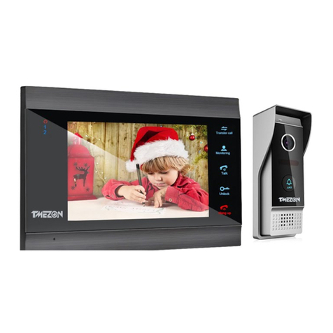
TMEZON
TMEZON MZ-IP-V739B Technical manual
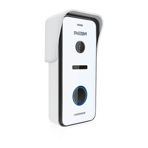
TMEZON
TMEZON MZ-VDP-HD739W User manual
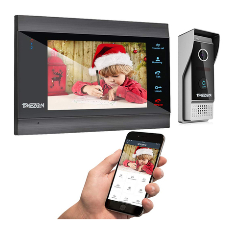
TMEZON
TMEZON MZ-IP-V739W User manual
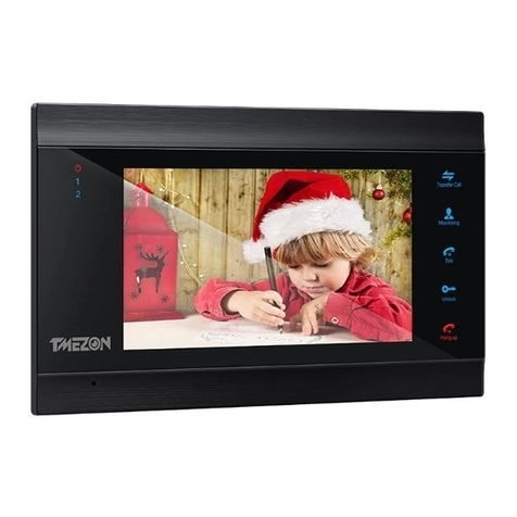
TMEZON
TMEZON MZ-VDP-NA200 Technical manual
TMEZON
TMEZON MZ-IP-V103W Technical manual
TMEZON
TMEZON MZ-VDP-NA262F User manual
TMEZON
TMEZON MZ-VDP-739EM Technical manual

TMEZON
TMEZON MZ-IP-V103W Quick start guide

TMEZON
TMEZON MZ-IP-V103W Technical manual
