manuals.online logo
Brands
  1. Home
  2. •
  3. Brands
  4. •
  5. TMG
  6. •
  7. Outdoor Furnishing
  8. •
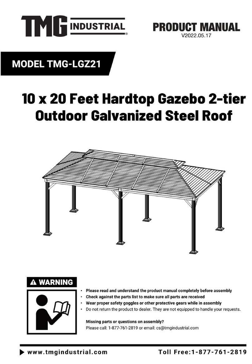
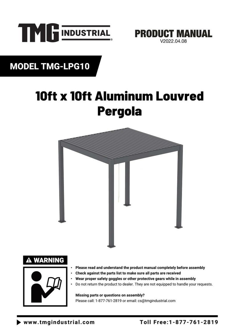
  9. TMG TMG-LPG21 User manual

TMG TMG-LPG21 User manual

►
www.tmgindustrial.com P0 / 19 Toll Free:1-877-761-2819
Main specifications
Overall assembled size : W4.88 x L7.5x H3.05 (m) / 16 x 24 x 10
(ft)
Front door : W3.6 x H2.0 (m) / 11.8 x 6.56 (ft)
Side door: W0.9 x H2.0 (m) / 2.95 x 5.56 (ft)
Prior to assembly
Please read the instructions carefully before installation. It is very
important to follow your local safety regulations and industry
standards during installation. Regulations may include but are not
limited to:
-Safety helmets, protective eyewear, and clothing
-Safety harnesses for all elevated workers
-Proper ladder, cage, and safety operation
Check all components and parts before installation. All parts are marked with
a part number, please refer to the parts list to make sure you have all parts.
Choose a day with low or no wind to install, assembly is hard in heavy wind.
Do not make any alterations to the structure. Do not hang any weights on the
frame during installation, including parts. We are not responsible for any
►
www.tmgindustrial.com P1 / 19 Toll Free:1-877-761-2819
Main Specifications:
Assembly size : W2.95 x L5.79 x H2.5 (m) / 10ft x 20ft x 8ft
Wind proof roller shutter : W2.73 x H2.325 (m)
fabric density : 5%
Prior to assembly
Please go through the whole instruction manual completely. It is very important to
follow your local safety regulations and industry standards during installation.
Regulations may include but are not limited to:
-
Safety helmets, protective eyewear, and clothing
-
Safety harnesses for all elevated workers
-
Proper ladder, cage, and safety operation
Check all components and parts before installation. All parts are marked with a part
number, please refer to the parts list to ensure you have all parts.
Choose a day with low or no wind to install, it is hard to assemble with heavy wind. Do
not make any alterations to the structure. Do not hang any weight on the frame during
installation, including parts. We are not responsible for any damages or injuries caused
by inappropriate installation, unauthorized modifications or extreme weather.
Check the parts list below to make sure all parts are received prior to assembly.
►
www.tmgindustrial.com P2 / 19 Toll Free:1-877-761-2819
TMG-LPG21 Part List
Parts
code
Graphical
Description
Length
Qty
A1
Post
110X110mm
6
A2
Base cover
190X190mm
6
A3
Base footing plate
170X170mm
6
A4
Base footing screw
4X35mm
36
A5
Expansion bolt
M8X7mm
24
A6
Post cover
110X110mm
4
A7
Post cover screw
4X16mm
24
A8
Small cover
18X18X2
4
B1-B4
Beam
80X140mm
6
B5
Rubber plug
8mm
56
B6
Sliding pin
35*17mm
86
B7
Sliding pin screw
4*16mm
172
C1-C43
Blade
149.98*43.8mm
43
C44
Letters
6*8*8mm
1
D1
L shape aluminum
plate
25*15mm
4
E
R-shape pin
1.8*35mm
86
F1
Front breakwater
65*15mm
1
F2
Front breakwater
screw
4*16mm
3
G1
Rear breakwater
125*26mm
1
►
www.tmgindustrial.com P3 / 19 Toll Free:1-877-761-2819
G2
Rear breakwater screw
4*16mm
5
H1
Hexagon spanner
3mm
2
I
Pergola remote control
1
J
Small rubber hammer
26*6*2mm
1
K
Cross head
65mm
2
L
Auger
3.4mm
1
M
5M Power line
5m
1
N
Silicon sealant
120ml
1
O
Residual circuit
breaker
125w
1
B10
Beam connection
105*35*2mm
2
A9
Aluminium tube
80*30*1mm
1
P1
Orbital left seal
49*38mm
6
P1-1
Left side orbital
49*38mm*2219mm
6
P1-2
Left side rubber tape
32*2219mm
6
►
www.tmgindustrial.com P4 / 19 Toll Free:1-877-761-2819
P1-3
Left side orbital cover
49*38*2219mm
6
P3
Screw for side orbital
cover
5*8mm
12
P4
Screw for Side orbital
4.2*38mm
60
P2
Orbital right seal
49*38mm
6
P2-1
Right side orbital
49*38mm*2219mm
6
P2-2
Right side rubber tape
32*2219mm
6
P2-3
Right side orbital
cover
49*38*2219mm
6
Q1
Front cover
100*100*2720mm
6
Q2
Rear cover
100*100*2720mm
6
Q3
Rolling fabric and
motor
2666*2565mm
6
Q4
Cover screw
4.2*25mm
36
►
www.tmgindustrial.com P5 / 19 Toll Free:1-877-761-2819
Step 1:Install base footing plate and beam
Lay the post A1 flat, install base cover A2 and base footing plate A3 on all post A1, and
drilling base footing screw A4. The step applies to the two post on the right
Install the beam, insert the ends of beam B1 into two post A1, and tighten the screws
Parts
code
Graphical
Qty
A4
24
A1
6
B1
1
A2
6
B3
1
A3
6
►
www.tmgindustrial.com P6 / 19 Toll Free:1-877-761-2819
Step 2: Install Beam B2、B2-1
Connect the electric wire of Beam B3 & B2,B2 & B2-1.
Connect the Beam B2 and B2-1 with Beam connection B10. Align with four holes and
install them on middle Post A1 with fixed drills.
Secure the Beam B2 and Beam B2-1 to Post A1.
Parts
code
Graphical
Qty
B10
1
B2-1
1
B2
1
►
www.tmgindustrial.com P7 / 19 Toll Free:1-877-761-2819
Step 3:Install B4、B4-1
The main power line passes under Post A1 and connects the power lines of B3 & B4,
B4 & B4-1, B4-1 & B1.
Connect the Beam B4 and B4-1 with Beam connection B10. Align with four holes and
install them on middle Post A1 with fixed drills.
Secure the Beam B4 and Beam B4-1 to Post A1.
Parts
code
Graphical
Qty
B10
1
B4-1
1
B4
1
►
www.tmgindustrial.com P8 / 19 Toll Free:1-877-761-2819
Step 4: Install Aluminium tube A9
Install Aluminum tube A9 on the two middle Post A1
Parts
code
Graphical
Qty
A9
1
►
www.tmgindustrial.com P9 / 19 Toll Free:1-877-761-2819
Step 5: Install Base footing plate A3
Measuring base distance,make the parallel distances and the diagonal distances equal.
Secure the base footing plate A3 with expansion bolt A5.
Parts
code
Graphical
Qty
A5
24
Step 6: Install Blades C1-C43
Install the blades C1--C43 in sequence, and drill the sliding pin screw B7 into sliding
pin B6 to fix it.
Connect all the blades with L shape aluminum D1 & D2, and plug R-shape pin E as
shown.
Connect LED light: the light line passed through the beam B4, B4-1 and connect the
power line according to the same color.
►
www.tmgindustrial.com P10 / 19 Toll Free:1-877-761-2819
All screw hole plugs with small rubber plug B5.
Parts
code
Graphical
Qty
D1
4
C1-C21
43
E
42
B5
56
B7
172
B6
86
D1
1
►
www.tmgindustrial.com P11 / 19 Toll Free:1-877-761-2819
Step 7:Install Front breakwater F1 and Rear breakwater G1
Parts
code
Graphical
Qty
F1
1
G1
1
F2
3
G2
5
►
www.tmgindustrial.com P12 / 19 Toll Free:1-877-761-2819
Step 8: Install Post cover A6
Parts
code
Graphical
Qty
A6
4
A8
4
A7
24
C44
2
►
www.tmgindustrial.com P13 / 19 Toll Free:1-877-761-2819
Step 9: Separate Front cover Q1
Remove the screws and open the Front cover Q1
2.Unscrew the two ends of Rolling fabric and motor Q3 and take Rolling fabric and
motor Q3 out.
Parts
code
Graphical
Qty
Q1
1
Q3
1
Q2
1
►
www.tmgindustrial.com P14 / 19 Toll Free:1-877-761-2819
Step10: Install Rear cover Q2
Install Rear cover Q2 and screw the screw on the Beam. (PS: please pay attention to
installation direction, please make sure the protruding side of the iron is on the outside)
Parts
code
Graphical
Qty
Q2
1
Q4
3
►
www.tmgindustrial.com P15 / 19 Toll Free:1-877-761-2819
Step 11:Install Left & Right side orbital P1-1 & P2-1.
Left & Right side orbital P1-1 & P2-1 are mounted on protruding iron blocks on both
sides of the Rear cover Q2.
Left & Right side orbital P1-1 & P2-1 screw 3pcs Screw for side orbital P4 in Post A1.
Parts
code
Graphical
Qty
P4
6
P1-1
1
P2-1
1
►
www.tmgindustrial.com P16 / 19 Toll Free:1-877-761-2819
Step 12: Install Orbital Left & Right seal P1 & P2 and Left & Right side rubber tape
P1-2 & P2-2.
Install Orbital Left & Right seal with Screw for side orbital P4.
Install Left & Right side rubber tape P1-2 & P2-2 on Left & Right side Orbital P1-1 &
P2-1. PS: The Left & Right side rubber tape P1-2 & P2-2 of the gap on the top.
Parts
code
Graphical
Qty
P2-2
1
P1
1
P2
1
P4
2
P1-2
1
►
www.tmgindustrial.com P17 / 19 Toll Free:1-877-761-2819
Step 13: Install Rolling fabric and motor Q3.
Install Rolling fabric and motor Q3,The fabric faces inward; Clip the fabric into Left &
Right side rubber tape P1-2 & P2-2.
Screw left and right sides of Rolling fabric and motor Q3.
Parts
code
Graphical
Qty
Q3
1
►
www.tmgindustrial.com P18 / 19 Toll Free:1-877-761-2819
Step 14:Install Left & Right side orbital cover P1-3 & P2-3 and Front cover Q1.
Install the Left & Right side orbital cover P1-3 & P2-3 , tap it with a small plastic
hammer J; Secure with Screw for side orbital cover P3.
Install Front cover Q1 and secure it with Cover screw Q4.
Parts
code
Graphical
Qty
P3
2
P1-3
1
P2-3
1
Q4
2
Q1
1
►
www.tmgindustrial.com P19 / 19 Toll Free:1-877-761-2819
Step 15:Connect electric wire.

Other TMG Outdoor Furnishing manuals

TMG PRO Series User manual

TMG

TMG PRO Series User manual

TMG TMG-LGZ21 User manual

TMG

TMG TMG-LGZ21 User manual

TMG TMG-LPG10 User manual

TMG

TMG TMG-LPG10 User manual

TMG TMG-LPG11 User manual

TMG

TMG TMG-LPG11 User manual

Popular Outdoor Furnishing manuals by other brands

Doppler Active Assembly instructions and user's manual

Doppler

Doppler Active Assembly instructions and user's manual

Arcane T18 manual

Arcane

Arcane T18 manual

Blooma Agad 3663602936299 quick start guide

Blooma

Blooma Agad 3663602936299 quick start guide

Royal garden URA03801A Use and care guide

Royal garden

Royal garden URA03801A Use and care guide

BENITO Citizen Eco UM301SPR quick start guide

BENITO

BENITO Citizen Eco UM301SPR quick start guide

Hesperide ALLURE 139075 manual

Hesperide

Hesperide ALLURE 139075 manual

Quest Leisure Products Quest Elite Bordeaux Pro Relax Full item instructions and extended details

Quest Leisure Products

Quest Leisure Products Quest Elite Bordeaux Pro Relax Full item instructions and extended details

SNOWJOE Sunjoy Santa Belle manual

SNOWJOE

SNOWJOE Sunjoy Santa Belle manual

Mainstays Landsdowne Heights Assembly & instruction manual

Mainstays

Mainstays Landsdowne Heights Assembly & instruction manual

Hanover Manor MANDN9PCSWSQ-8 Assembly instructions

Hanover

Hanover Manor MANDN9PCSWSQ-8 Assembly instructions

Safavieh Outdoor PAT1508A Assembly

Safavieh Outdoor

Safavieh Outdoor PAT1508A Assembly

Simply Log Cabins Pavilion PAV-5546 installation manual

Simply Log Cabins

Simply Log Cabins Pavilion PAV-5546 installation manual

Crate and Barrel 450515 Assembly instructions

Crate and Barrel

Crate and Barrel 450515 Assembly instructions

Sunjoy S-GZ1182PST Use and care guide

Sunjoy

Sunjoy S-GZ1182PST Use and care guide

DTY Broadmoor OF-1001 quick start guide

DTY

DTY Broadmoor OF-1001 quick start guide

Palram Lean To Grow House 4x2 manual

Palram

Palram Lean To Grow House 4x2 manual

Ivy Terrace IVA22 Assembly instructions

Ivy Terrace

Ivy Terrace IVA22 Assembly instructions

Perfect Choice Single Glider Assembly instructions

Perfect Choice

Perfect Choice Single Glider Assembly instructions

manuals.online logo
manuals.online logoBrands
  • About & Mission
  • Contact us
  • Privacy Policy
  • Terms and Conditions

Copyright 2025 Manuals.Online. All Rights Reserved.