TMG TMG-ABC28 User manual

28 GALLON ABRASIVE
SANDBLASTER WITH VACUUM
PRODUCT MANUAL
v2023.08.26
TMG-ABC28
Please read and understand the product manual completely before assembly
Check against the parts list to make sure all parts are received
Wear proper safety goggles or other protective gears while in assembly
Do not return the product to dealer. They are not equipped to handle your requests.
Missing parts or questions on assembly?

SAVE THESE INSTRUCTIONS
Thank you for purchasing your Abrasive Blaster with Vacuum. Before attempting to operate your new Abrasive Blaster please
read these instructions thoroughly. You will need these instructions for the safety warnings, precautions, assembly, operation,
maintenance procedures, parts list and diagrams. Keep your invoice*- with these instructions. Write the invoice number on the
inside of front cover Keep the instructions and invoice in a safe, dry place for future reference.
The warnings, cautions and instructions discussed in this instruction manual cannot cover all possible conditions or
situations that could occur. It must be understood by the operator that common sense and caution are factors which
cannot be built into this product, but must be supplied by the operator.
Silicosis and other Dust Warnings: Breathing dust from silica sand may cause silicosis, a fatal lung disease. Breathing dust during
blasting operations may also cause asbestosis and/ or other serious or fatal diseases. A NIOSH-approved, well maintained air
supplied abrasive blasting respirator must be used by anyone blasting, anyone handling or using media containing toxic
substances or media with more than one percent free crystalline silica and anyone in the area of the dust. Harmful dust can
remain suspended in the air for a long periods of time after blasting has ceased, causing serious injury or death.
Before removing respirator, use an air monitoring instrument to determine if atmosphere is safe to breathe. Contact local OHSA
or NIOSH office to determine if the proper respirator for your particular application.
Air supplied respirators do not remove or protect against carbon monoxide (CO) or any other toxic gas. Use a carbon monoxide
removal device and monitoring device with the respirator to ensure grade D quality air. Follow all applicable OSHA standards and
OSHA regulation 1910.134 (d).
Disclaimer of Warranties. Manufacture,distributor and TMG Industrial makes no warranties with respect to any goods delivered to
buyer or users except as specifically set forth within this manual. TMG Industrial makes no implied warranties of merchantability
or fitness for a particular purpose with respect to any of the goods, and setter expressly disclaims any implied warranties against
infringement TMG Industrial warranties shall not apply to any damage or non-conformity resulting from the negligent & improper
assembly or use of any goods by users or buyer or its employees or agents, or from alteration or attempted repair by any person
other than the manufacturer. All used,repaired,modified or altered items are purchased as-is and with all faults.
Vacuum....................................................................................................................................................................120V/60Hz, 10.5A
Working pressure..........................................................................................................................................................80-115PSI
Air consumption...................................................................................................................................................6-22.5CFM@115PSI
Abrasive media capacity..............................................................................................................................................................4GAL
READ ALL INSTRUCTIONS BEFORE OPERATING
SPECIFICATIONS

A. Electric switch
B. Handle
C. Air hose
D. Vacuum hose
E. Abrasive tank
F. Abrasive hose
G. 6" rubber wheel
H. 4” caster wheel
I . Blast gun assembly
COMPONENTS AND CONTROLS
G
D
F
C
A
B
E
I
H

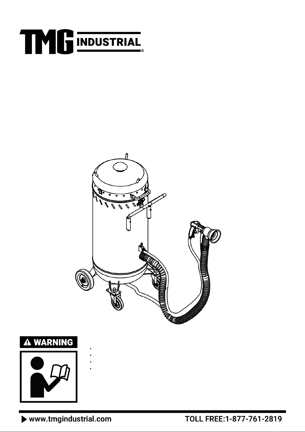
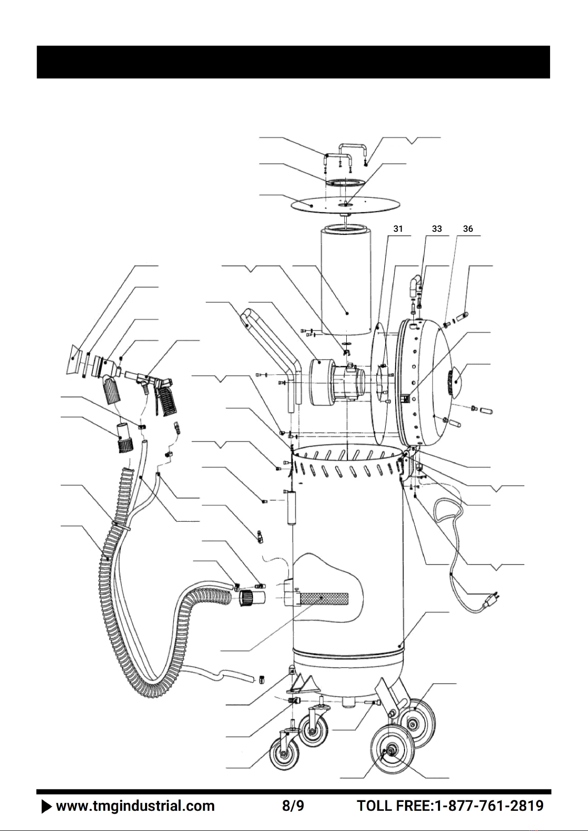
SAFETY DECAL LOCATIONS
SAFETY RULES
1. Know your machine. Read this manual carefully. Learn the machine’s applications
and limitations, as well as specific potential hazards peculiar to it.
2. Ground all machines. If the machine is equipped with three-pin plug, it should be plugged into a three-pin electrical socket.
Never remove the ground pin.
3. Avoid body contact with grounded surfaces such as pipes, radiators, ranges, and refrigerators. There is an increased risk of
electric shock if your body is grounded.
4. Do not expose tool to moisture. Don't use this machinery in damp or wet locations. Keep out of rain.
5. Do not abuse cord. Never use the cord to carry tools or pull the plug from an outlet. Keep cord away from heat, sharp edges or
moving parts. Replace damaged cords immediately. Damaged cords increase the risk of electric shock.
6. Remove adjusting keys or wrenches before turning the tool on. A wrench or key that is left attached to a moving part of the
tool may result in personal injury.
7. Keep work area clean and well lit. Cluttered or dark work areas invite accidents.
8. Keep children away. All children should be kept away from the work area. Never let a child handle a tool without strict adult
supervision.
9. Do not operate this tool if under the influence of alcohol or drugs. Read warning labels on descriptions to determine if your
judgment or reflexes are impaired while taking drugs. If there is any doubt, do not attempt to operate.
10. Use safety equipment. Eye protection should be worn at all times when operating this machine. Use ANSI approved safety
glasses. Every- day eyeglasses only have impact resistant lenses. They are NOT safety glasses. Niosh approved breathing
apparatus, nonskid safety shoes, hard hat, gloves or hearing protection should be used in appropriate conditions.
11. Wear proper apparel. Loose clothing, gloves, neckties, rings, brace- lets, or other jewelry may present a potential hazard when
operating this machine. Please keep all apparel clear of the machine.
12. Don't overreach. Keep proper footing and balance at all times when operating this product.
13. Always disconnect the machine before making any adjustments, storing, servicing, or changing accessories. Such
preventative safety measures reduce the risk of starting the tool accidentally.
14. Use clamps or other practical means to secure and support the work piece to a stable platform. Holding the work by hand or
against your body may lead to a loss of control.
15. Do not force tool. Use the correct tool for your apolication. The correct tool will do the job better and safer at the rate for
which it was designed.
16. Do not use the tool if the switch does not turn it on and off. Any tool that cannot be controlled with the switch is dangerous
and must be repaired.
17. Check for damage. Check your tool regularly. If part of the tool is dam-
aged it should be carefully inspected to make sure that it can perform it's intended function correctly. If in doubt, the part should
be repaired. Refer all servicing to a qualified technician. Consult your dealer for advice.
18. Keep away from flammables. Do not attempt to operate this tool near flammable materials or combustibles. Failure to comply
may cause serious injury or death.
19. Store idle tools out of the reach of children and untrained persons. Tools may be dangerous in the hands of untrained users.
SAFETY LABELING
4063
4062

Before operating read technical data and instructions for use.
1. Open carton and remove the following contents:
1 plastic bag containing Instruction Manual.
1 plastic bag containing Brush Head Assemblies.
1 plastic bag containing Wheels, Castors and a smaller Hardware Bag.
1 Wheel Axis
1 Handle
2. Lay carton on its side to take the unit out.
3. Remove all packing materials from abrasive blaster. Release the two snap locks on the vacuum assembly and remove the
vacuum head to take the Vacuum Hose and Abrasive Hose out.
4. Install the castors and the wheels on the frame base. Install the handle on the tank.
5. Fill 20-35 lbs. of abrasive into the bottom container.
6. Reattach the vacuum head to the tank, making certain both snap locks are securely locked down.
7. Insert the end of Vacuum Hose with Coupler into the tank, and screw the other end without coupler in the coupler on the brush
head assembly. Install one end of the Abrasive Hose with a hose clamp on the end of the male air connector. Install the other end
of Abrasive Hose with a hose clamp on the abrasive outlet manifold.
Note: Ideal operating air pressure is 115 psi. DO NOT exceed 140 psi.
You are now ready to begin work with your Abrasive Blast/Vacuum.
ASSEMBLY INSTRUCTIONS

1. If protective head gear and respiration is not already in place, put it on now .
2. Set air compressor to 115 psi. (More or less, depending on the surface to be cleaned.)
3. Connect air hose coupling to air coupling connector located on gun handle.
4. Connect power cord to power source.
5. With gun pointed at surface to be cleaned, turn the power switch on the vacuum head to the ON position.
6. Have one hand holding the gun while the other hand holds the brush handle. Note: Do not apply pressure with the brush against
the surface being cleaned! The brush function is only intended to prevent abrasive waste and to develop and maintain a closed
vacuum cycle for the abrasive to be recycled. The brush is NOT intended to assist in the abrasion process.
7. Move both hands in the direction where rust removal or pre-finish work is required.
8. By lenthening or shortening the nozzle with the set nut, you will vary the size of the blast stream.
9. The bristle brush is for flat surfaces and also for angles and corners. Before starting, spread out the bristles in such a way that
it does not cover the jet spray inside the brush. (The abrasives will eventually wear out the bristles). On car door edges, we
recommend that you wrap the bristles around the edge, which will generate better vacuum, better coverage, safety, and results.
10. After each job, lift off vacuum head and knock dust from the filter. After 1 hour of continuous blasting, lift out the vacuum
head and blow off dust with direct air or vacuum.
11. When blasting a 90 degree corner, align the gun at a 45 degree angle to reach the deepest area. Move the gun in a slow,
circular motion for best results.
When finished with your Abrasive Blaster, unsnap the two retaining clamps, empty dust container and store the Abrasive
Blaster in a safe, dry location.
OPERATING INSTRUCTIONS

Symptom
Probable Cause
Possible Solution
Decrease in blast performance
1. Possible low air pressure
2. Moisture in the abrasive
3. Dirty Filter
4. Abrasives are "worn" or too fine
5. Gun Blockage
- Check air compressor and hose for leaks.
- Verify CFM input is compatible with blaster
/ vacuum
- Air must be clean and dry. Suggest airline filter.
- Clean filter thoroughly
- Change abrasive
- Disconnect air and power, unscrew nozzle and
remove blockage with a paper clip or thin
wire.
Decrease in vacuum performance
1. Dirty Filter
2. Blocked or leaking vacuum line
3. Insufficient air flow
- Clean filter thoroughly
- Inspect all vacuum lines for blockage or
damage, clean or replace as necessary.
- Check CFM input at airline connector point.
Abrasive is coming out between the
bristles of the brush
1. Too much air pressure
2. Blockage in the vacuum system
- Check air pressure and adjust accordingly
- Inspect all vacuum lines for blockage or
damage, clean or replace as necessary.
TROUBLESHOOTING GUIDE

1. Exploded diagram
EXPLODED VIEW & PARTS LIST
31
33
36
1
2
5
6
3
4
7
8
9
10
11
55
6
12
13
19
18
17
16
15
14
20
21
24
22
23
27
26
25
28
29
30
34
35
32
37
38
39
40
42
43
44
46
45
41
47
49
51
50
48
54
52
53

2. Parts List
PART NO.
DESCRIPTION
QTY
PART NO.
DESCRIPTION
QTY
1
Vacuum hose Ø38X2500
1
29
Spring washer Ø4
4
2
Wireclip 4x260
10
30
Long bolt M6x310
1
3
Abrasive hose Ø18X3100
1
31
Motor lift Ø372x2
1
4
Air hose Ø17X2700
1
32
Cross recessed pan head tapping
screw
4
5
Coupler
2
33
Handle 2 Ø19
1
6
Clamp Ø13-19
4
34
Bolts M8x30 with spring washer
2
7
Brush head Ø100X62x40
1
35
Cable pole
3
8
Hoop Ø70
1
36
Bolts M8x12 with spring washer
3
9
Blast heed
1
37
Electric switch
1
10
Hex screw M6x10
1
38
Cover assembly
1
11
Blast gun body
1
39
Support of cover
1
12
G1/4” air inlet fitting
2
40
Rotational axle Ø6x10²
1
13
Quick connector
1
41
Nut M6 with plain washer Ø6
2
14
Hex screw M6x12
2
42
Cable nut
1
15
Cross recess head screw M4x10
2
43
Cross recess pan head screw M5x20
5
16
Nuts M4
2
44
Nut M5 with spring washer Ø5
5
17
Latch
1
45
Power cable
1
18
Cross recess head screw M6x16
6
46
Hinge
1
19
Plain washer and Spring washer Ø6
6
47
Abrasive tank
1
20
Handle Ø19x787
1
48
6" rubber wheel
2
21
Vacuum motor
1
49
Plain washer Ø12
2
22
Ring
1
50
Split pin 4x36
2
23
Butterfly nut M6
1
51
Air adapter M10x45
1
24
Air filter Ø170x310
1
52
4” caster wheel M12x25
2
25
Cover
1
53
Air connector G3/8”
1
26
Rubber pad Ø136x Ø98x3
2
54
Nut M12
2
27
Handle Ø19
2
55
Screen cap assembly
1
28
Cross recess head screw M4x10
4
Table of contents
Other TMG Power Tools manuals