TMG TMG-ARB04 User manual

►www.tmgindustrial.com 1/6 TOLL FREE:1-877-761-2819
SAFETY INFORMATION
Save these instructions. For your safety, read, understand, and follow the information provided with and on this product
before using. The owner and/or operator of this equipment shall have an understanding of safe use/operating procedures
before attempting to use. The owner and/or operator shall be aware that the use of this product may require special skills
and knowledge. Instructions and safety information shall be conveyed in the operator's native language before use of this
device is authorized. If any doubt exists as to the safe and proper use of this product as outlined in this factory authorized
manual remove from service immediately.
Inspect before each use. Do not use if broken, bent, cracked, or damaged parts (including labels) are noted. If the product
appears damaged in any way, operates abnormally or is missing parts, it should be removed from service immediately and
the manufacturer notified. If you suspect that the product was subjected to a shock load (a load suddenly dropped
unexpectedly upon it, immediately discontinue use until product has been checked by a factory authorized service center
(contact distributor or manufacturer for list of Authorized Service Centers). It is recommended that an annual inspection
be done by qualified personnel. Labels and owner's manuals are available from manufacturer.
INSTRUCTIONS
⚠WARNING
1. READ, STUDY AND INDERSTAND ALL WARNING AND OPERATING INSTRUCTIONS PRIOR TO ISE.
2. STEEL AND OTHER MATERIALS CAN FAIL OR SHATTER UNDER STRONG PRESSURE, ALWAYS WEAR
PROTECTIVE EYE WEAF (GLASSES, GOGGLES OR/AND FACE SHELL) THAT COMPLIES WITH THE
APPROPRIATE ANSI CODE
3. IF YOU DETECT OR EVEN SUSPECT ANYTHING THAT MAY INDICATE IMMINENT STRUCTURAL FAILURE, STOP!
DON'T USE THE PUMP INSPECT BEFORE EACH HSE.
4. WHEN COUPLER VALVES ARE DISCONNECTED, ALWAYS INSERT DUST CAP TO KEEP THE OIL LINES CLEAN.
5. DO NOT DROP ANY HEAVY OBJECTS ONTO THE HOSE, AND DO NOT ALLOW THE HOSE TO KINK.
6. ALWAYS ALLOW CLEARANGE FOR THE HOSE TO AVOID DAMAGE TO THE HOSE AND COUFLERS.
7. KEEP THE EQUIPMENT AWAY FROM HEAT OR FIRE, AS THIS MAY DAMAE OR WEAKEN THE EQUIFMENT.
8. FAILURE TO HEED THESE WARNINGS MAY RESULT IN DAMAGE TO EQUPMENT AND/OR FAILURE RESULTING
IN PERSONA INJURY OR PROPERTY DAMAGE.
9. INSPECT BEFORE EACH USE.
⚠DO NOT USE THIS DEVICE FOR ANY PURPOSE OTHER THAN THAT FOR WHICH IT IS EXPRESSLY INTENDED
PRODUCT DESCRIPTION
Portable Power Kits are designed to be used for pushing, spreading, and pressing of vehicle body panels as well as
various component parts and assemblies. Rams are rated from 4 to 10 tons respectively.
⚠WARNING: To reduce the risk of personal injury and/or property damage, ensure that the rated working pressure of
each pressurized attachment be equal to or greater than the rated working pressure developed by the hydraulic pump.
Always check connections before using. Alteration of these products is strictly prohibited. Use only those adapters and
attachments provided and approved by the manufacturer.
Note, when extension tubes and/or offset attachments are used, the rated capacity is always reduced by 50% for each
tube or offset attachment connected

►www.tmgindustrial.com 2/6 TOLL FREE:1-877-761-2819
ASSEMBLY INSTRUCTIONS
TO ASSEMBLE HYDRAULIC RAM, PUMP UNIT, AND ATTACHMENTS
1. Unscrew and save the End Plugs located on the ends of the Hose and Hydraulic Ram.
2. Securely screw the Hose into the Hydraulic Ram.(See Figure A)
Figure A
3. Insert the Pump Handle into the receptacle located at the top of the Pump Unit.
4. To attach the Rubber Head, the Extension Bars, the Male Connector, and the Flat Base to the Hydraulic Ram, see
Figure A
5. To attach the Spreader Wedge to the Pump Unit, see Figure B.
Figure B
6. For other attachment combinations see Figure C.
Figure C

►www.tmgindustrial.com 3/6 TOLL FREE:1-877-761-2819
OPERATING INSTRUCTIONS
TO OPERATE THE HYDRAULIC PUMP UNIT
1. Position the Pump Unit on a stable, flat and level surface close to the damaged area.
2. Firmly close the Release Valve Stem by turning it clockwise and pump the Pump Handle to apply pressure.
3. Turn the Release Valve Stem counterclockwise to release the pressure.
4. The Pump Unit may be positioned horizontally or vertically. When using the hydraulic unit in a vertical position, always
keep the hose end of the hydraulic unit downward.
TO REPAIR FRAME DAMAGE
1. Determine which direction the frame needs to be bent.
2. Remove any obstructions that could be damaged or are in the way.
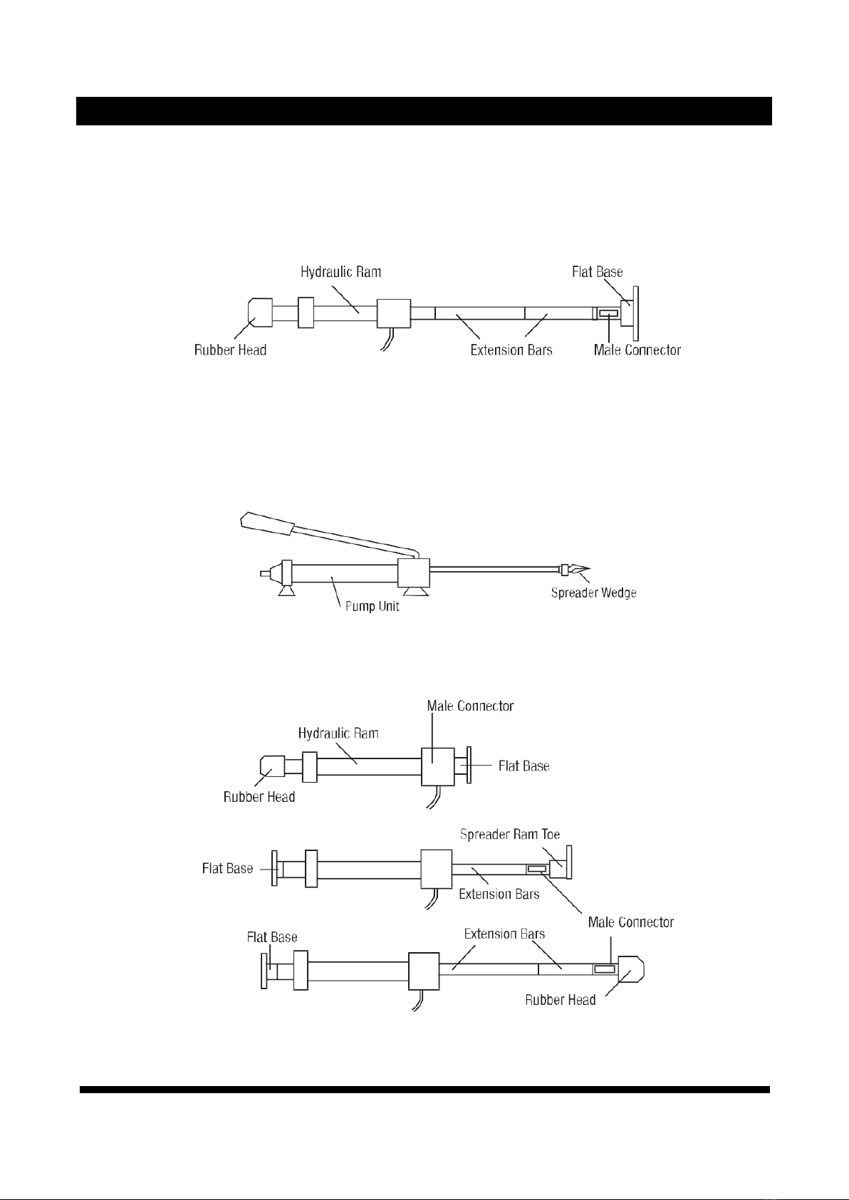
3. Connect the Flat Base to the stationary side of the Hydraulic Ram and connect the appropriate attachment to the
pushing end of the Stroke Ram.
4. Position the Hydraulic Ram so that the Flat Base is resting against a frame member opposite the damaged area. It
must also be in line with the direction in which the damaged area needs to be pushed.
5. Aim the pushing end towards the area that needs to be repaired and slowly apply pressure with the Pump Unit.
6. Once contact on either end has been made, step away as far as possible and continue to slowly apply pressure to the
damaged area until the desired bend has been made.
CAUTION: Keep hands away from contact areas and tight spaces. The Portable Power Kit may slip and cause injury.
7. When the damaged area has been bent to the desired position, slowly turn the Release Valve Stem on the Pump Unit
in a counterclockwise direction to release the hydraulic pressure and remove the Hydraulic Ram.
TO REPAIR BODY DAMAGE
1. Determine which direction the body panel should be moved.
2. Remove any obstructions that could be damaged or are in the way.
3. Connect the appropriate attachments to the Hydraulic Ram.
Note: When repairing larger body panel dents such as a dented door, fender or quarter-panel, the proper pushing
attachment will be the Rubber Head.
4. Position the Hydraulic Ram so that the Flat Base is resting against a frame or a sturdy body part opposite the
damaged area. It must also be in line with the direction in which the damaged area needs to be pushed. Make sure
the body part is stronger than the area to be bent or it may be damaged. A block of wood or a towel may be used to
protect the body part.
5. Aim the pushing end towards the area that needs to be repaired and slowly apply pressure with the Pump Unit.
6. Once contact on either end has been made, step away as far as possible and continue to slowly apply pressure to the
damaged area until the desired bend has been made.
7. When the damaged area has been bent to the desired position, slowly turn the Release Valve Stem on the Pump Unit
in a counterclockwise direction to release the hydraulic pressure and remove the Hydraulic Ram.

►www.tmgindustrial.com 4/6 TOLL FREE:1-877-761-2819
TO USE THE SPREADER WEDGE
1. Determine which direction the frame needs to be bent.
2. Remove any obstructions that could be damaged or are in the way.
3. Place Spreader Wedge so that the hinged arm is resting against the part to be moved and the stationary arm is resting
against a non-movable base. Hold the spreader Ram in position and apply the Pump Unit pressure.
4. Once contact on either end has been made, step away as far as possible and continued to slowly apply pressure to
the damaged area until the desired bend has been made.
5. When the damaged area has been bent to the desired position, slowly turn the Release Valve Stem on the Pump Unit
in a counterclockwise direction to release the hydraulic pressure and remove the Hydraulic Ram.
CARE AND MAINTENANCE
1. Determine which direction the frame needs to be bent.
2. Before each use, examine the general condition of the tool. Inspect the tool and its accessories for damage. Check
for loose bolts. misalignment, binding of moving parts, broken parts and any other condition that may affect its safe
operation.
Do not use a damaged tool or its damaged accessories
3. When the Portable Puller Set is not in use, the Pump Unit should be stored with the Release Valve Stem open.
4. After extensive use, the hydraulic oil supply should be replaced to ensure longer equipment life.
5. To check the oil level:
a. Set Pump Unit flat on a level surface.
b. Remove the Screw with its attached dipstick.
c. The oil level should be near the bottom of the opening. If required, add high grade hydraulic oil
d. Replace the Screw.
6. To bleed the pump:
a. Check the oil level and fill if necessary, following procedures for checking the oil level.
b. Firmly close the release valve stem by turning it clockwise.
c. To bleed the pump, press the tip of the coupling against a hard surface and pump the pump handle.
d. Continue pumping until the hydraulic fluid coming out from the end of the coupler tip is free of air bubbles.
e. Recheck the oil level and add oil if necessary.
f. Turn the release valve stem counterclockwise to release the pressure in the pump and hose.

►www.tmgindustrial.com 5/6 TOLL FREE:1-877-761-2819
REPLACEENT PARTS LIST
Not all components of the jack are replacement items but are illustrated as a convenient reference of location and
position in the assembly sequence. When ordering parts, give model number, serial number and description below.
PART
DESCRIPTION
QTY
1
Extension Tube 19-1/2”
1
2
Extension Tube 16-1/2”
1
3
Extension Tube 8-1/2”
1
4
Extension Tube 4-9/10”
1
5
Extension Tube 3”
1
6
Pump Unit
1
7
Ram assembly
1
8
Wedge Head(offset)
1
9
Rubber Head
1
10
Combination Head
1
11
Serrated Saddle
1
12
Male Connector
1
13
Plunger Toe(offset)
1
14
Spreader(1000lb. Capacity)
1
15
Ram Toe(offset)
1
16
Flat Base
1

►www.tmgindustrial.com 6/6 TOLL FREE:1-877-761-2819
TROUBLESHOOTING
SYMPTOM
POSSIBLE CAUSES
CORRECTIVE ACTION
Ram won’t lift load
Releases valve not tightly closed.
Overload condition air trapped in
system
Firmly close release valve.
Remedy overload condition
Purge away air from system
Ram won’t maintain hold
Release valve not tightly close.
Hydraulic unit malfunction
Firmly close release valve
Replace ram and/or pump
Ram won’t lower after unloading
Reservoir overfilled linkage binding
Drain oil to proper level.
Clean and lubricate moving parts
Ram won’t extend to full stroke
Oil level low
Add hydraulic oil
Poor performance
Oil level low.
Air trapped in system.
Add hydraulic oil
Purge away air from system.
WARRANTY
ONE YEAR LIMITED WARRANTY
For a period of one year from date of purchase, the manufacturer will repair or replace, at its option, without charge, any
of its products which fail due to a defect in material or workmanship, or which fail to conform to any implied warranty not
excluded hereby.
Performance of any obligation under this warranty may be obtained by returning the warranted product, including dated
purchase receipt, to the retailer or distributor where the product was purchased.
For warranted service during the warranty period, the product must be returned to the retailer. Consumers should only
submit product for repair directly to a warranty repair facility after the product warranty has expired. For the nearest
approved Service Repair Facility, contact 1-877-761-2819, 8a.m.- 5p.m. PST, Monday -Friday.
ALL WARRANTY SERVICE DURING THE WARRANTY PERIOD MUST BE HANDLED DIRECTLY THROUGH THE RETAILER.
Except where such limitations and exclusions are specifically prohibited by applicable law. (1) the CONSUMER'S SOLE
AND EXCLUSIVE REMEDY SHALL BE THE REPAIR OR REPLACEMENT OF DEFECTIVE PRODUCTS AS DESCRIBED ABOVE,
and (2) THE MANUFACTURER SHALL NOT BE LIABLE FOR ANY CONSEQUENTIAL OR INCIDENTAL DAMAGE OR LOSS
WHATSOEVER, and (3) THE 'DURATION OF ANY AND ALL EXPRESSED AND IMPLIED WARRANTIES, INCLUDING,
WITHOUT LIMITATION, ANY WARRANTIES OF MERCHANTABILITY AND FITNESS FOR A PARTICULAR PURPOSE, IS
LIMITED TO A PERIOD OF ONE YEAR FROM DATE OF PURCHASE.
This warranty gives you specific legal rights, and you may also have other rights which vary from state to state.
This manual suits for next models
1
Table of contents
Popular Service Equipment manuals by other brands

Rupes
Rupes S145EL START-UP, OPERATING AND MAINTENANCE INSTRUCTIONS

CEMO
CEMO DT-Mobil Easy 210I manual

Heavy Equipment Repair
Heavy Equipment Repair TRACBUSTER 2000 Operation manual

BGS technic
BGS technic 2852 instruction manual

K Tool International
K Tool International HD KTI-62116A owner's manual

Jet
Jet JOFC-36 Operation manual