TMG TMG-DT3080-PRO User manual

W W W . T M G I N D U S T R I A L . C O M P 0 / 1 7 T o l l F r e e : 1 - 8 7 7 - 7 6 1 - 2 8 1 9

W W W . T M G I N D U S T R I A L . C O M P 1 / 1 7 T o l l F r e e : 1 - 8 7 7 - 7 6 1 - 2 8 1 9
Main Specifications :
Assembly size : W9.15 x L24 x H6 (m) / 30 x 80 x 20 (ft)
Ridge height : 6m / 20 ft
Peak clearance : 5.4m / 18 ft
Front and back door : 4.27 x 3.96 (m) / 14 x 13 (ft)
Shoulder height : 3.6 m / 12ft
Prior to assembly
Please go through the whole instruction manual completely. It is very important to
follow your local safety regulations and industry standards during installation.
Regulations may include but are not limited to :
-
Safety helmets, protective eyewear, and clothing
-
Safety harnesses for all elevated workers
-
Proper ladder, cage, and safety operation
Check all components and parts before installation. All parts are marked with a part
number, please refer to the parts list to ensure you have all parts.
Choose a day with low or no wind to install, it is hard to assemble with heavy wind.
Do not make any alterations to the structure. Do not hang any weight on the frame
during installation, including parts. We are not responsible for any damages or
injuries caused by inappropriate installation, unauthorized modifications or extreme
weather.
This building is not intended for human occupancy.
It is recommended to use heavy duty duct tapes to tape the tube connection joint spots
to protect the cover from damage and worn. It will help to extend the cover life span.
Check the parts list below to make sure all parts are received prior to assembly.

W W W . T M G I N D U S T R I A L . C O M P 2 / 1 7 T o l l F r e e : 1 - 8 7 7 - 7 6 1 - 2 8 1 9
TMG-DT3080-PRO Part List
Parts
Code
Graphical
Description
Quantity
BOX
1
Peak arch tube
(for 9 middle trusses )
9
B
1A
Peak arch tube
(for front and rear truss)
2
B
2
Upper rafter tube
(for middle trusses)
18
A
2A
Upper rafter tube
(for front and rear truss)
4
A
3
Shoulder tube
(for middle trusses)
18
B
3A
Shoulder tube
(front and rear trusses)
4
B
4
Sidewall tube
(middle trusses)
18
A
4A
Sidewall tube
(front and rear left truss)
2
A
4B
Sidewall tube
(front and rear right truss)
2
A
5
Roof purlin
(horizontal tube)
90
A
5L
Baseplate for front and rear
truss left corners
2
B
5R
Baseplate for front and rear
truss right corners
2
B
6L
Left baseplate of front and rear
door frame
2
B

W W W . T M G I N D U S T R I A L . C O M P 3 / 1 7 T o l l F r e e : 1 - 8 7 7 - 7 6 1 - 2 8 1 9
6R
Right baseplate of front and
rear door frame
2
B
7
Baseplates for middle truss
18
B
7A
Ratchets
50
B
7B
Expansion bolts φ16
104
B
8
Ceiling cross bar
(front and rear truss)
2
B
9
Ceiling cross bar
(front and rear truss)
2
B
9L
Front and rear vertical door rail
(left side upper part)
2
B
9R
Front and rear vertical door rail
(right side upper part)
2
B
9A
Side door left tube
2
B
9B
Side door right tube
2
B
9C
Side door
2
B
10
Door center vertical supporting
rod for cross beam
(front and rear truss)
2
B
10L
Front and rear vertical door rail
(left side lower part)
2
B
10R
Front and rear vertical door rail
(right side lower part)
2
B
11
Door frame horizontal tube
(front and rear truss)
6
B

W W W . T M G I N D U S T R I A L . C O M P 4 / 1 7 T o l l F r e e : 1 - 8 7 7 - 7 6 1 - 2 8 1 9
11C
Side door upper tube
2
B
12
Bottom tension bar
(front and rear truss)
2
B
12B
Bottom tension bar
2
B
13
Front and rear door hand winch
crossing tube
2
B
14
Top cover tension tube
(for both bottom sides)
2 groups
A
15
Front roll up door dropping
tubes (to connect #16)
14
A
16
Front roll up door dropping
tubes (to connect #15)
14
B
17
Sidewall frame steel tension
cables
24
B
18
Ridge steel tension cables
(front and rear trusses)
24
B
19
Middle truss crossing steel
tension cables
9
B
20
Front and rear truss left and
right steel cables
4
B
21
Tie down straps (for #7A and
front and rear arches)
50
B
21A
Tube clamps (φ25)
28
B
22
Cable connection plate
36
B
22A
Pressing plate
12
B
22B
Pressing plate
2
B
23
Roll up door hand winch
2
B
23A
Wire rope for front and rear
door hand winch
2
B
23B
Right pulley system for front
and rear doors
2
B
23C
Left pulley system for front and
rear doors
2
B
24
Front and rear vertical door rail
connection plate
4
B

W W W . T M G I N D U S T R I A L . C O M P 5 / 1 7 T o l l F r e e : 1 - 8 7 7 - 7 6 1 - 2 8 1 9
24A
Front and rear vertical door rail
end plate (floatable to keep
door rail straight)
4
B
25
Tension tube end water plug
12
B
26
Tube clamps (φ48)
6
B
27
Hex bolt
M10x30mm and nuts
28
B
28
Self locking bolt
M10x70mm and nuts
99
B
29
Strengthened bolt
M12x30mm and nuts
220
B
30
Hex bolt
M10x50mm and nuts
14
B
31
Hex bolt
M10x70mm and nuts
68
B
32
Braided rope
(tie to front and back doors)
1 bundle
B
33
Roof fabric tarp cover
1
B
34
Front and rear truss cover
panel
2
B
35
Front and rear roll up door
cover panel
2
B
36
Front and rear fabric tarp
secure pin
2
B
37
Plastic hose (in grooves at both
ends of #33)
10
B
37A
Connector
(for connection #37)
8
B
38
Scratch resistant tape
4
B
39
Tapping screw (#12x25mm)
120
B

W W W . T M G I N D U S T R I A L . C O M P 6 / 1 7 T o l l F r e e : 1 - 8 7 7 - 7 6 1 - 2 8 1 9
Installation steps
Step 1 : Review the whole structure and choose the proper installation site
Choose a solid level ground area to set up the building. Do not install in an area
where the floor is soft, a wetland, can not take the weight, or keep the building steady.
We strongly recommend to install the building on a concrete foundation with all
expansion bolts to secure all baseplates. Do not use any anchor spikes!
Watch the surroundings! Do not set up the building near any snowdrifts. The fabric
cover can hold up a certain amount of falling leaves, light debris and wind resistance,
however, large, fast or sharp falling items and big wind might punch or tear the fabric
materials. Keep the building surroundings clear to avoid potential damages.
Be careful with power and heat sources. Do not keep heat sources near the cover. Do
not expose the building to open flame.
Review the whole frame structure diagram as shown in figure 1, decide the
roll up door position, and make sure you will have about 3 ft clearance around
the building.
Draw a rectangular square base line showing all positions of base plates and
front and rear doors. The diagonal X and Y must be equal. ( Refer to figure1)
Baseplates : all baseplates must be bolted firmly with expansion bolts(#7B). It
is concrete expansion bolt.
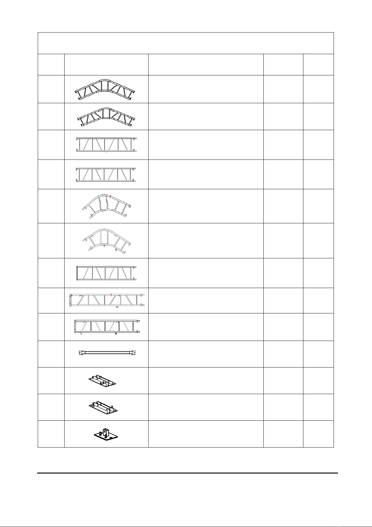
Baseplate installation is as below and all baseplates are required to install and
tie firmed on this step. (refer to figure 1)
-
(4) Baseplates (#5L, #5R)
-
(18) Baseplates (#7)
-
(4) Baseplates (#6L, #6R)
-
(96) Expansion bolts (#7B)
Figure 1

W W W . T M G I N D U S T R I A L . C O M P 7 / 1 7 T o l l F r e e : 1 - 8 7 7 - 7 6 1 - 2 8 1 9
Step 2 : Assemble all trusses
The building includes 11 trusses : (1) front truss, (1) rear truss, and (9) middle
trusses. The front and rear truss installed with the fabric panel (#34) and roll
up door (#35).
Parts used to install the front truss and rear truss in this step. (refer to figure 2)
-
(1x2) Peak arch tube (#1A)
-
(2x2) Upper rafter tube (#2A)
-
(2x2) Shoulder tube (#3A)
-
(1x2) Sidewall tube (#4A)
-
(1x2) Sidewall tube (#4B)
-
(12x2) Strengthened bolt (#29)
Figure 2
Parts used to install (9) middle trusses in this step. (refer to figure 3)
-
(1x9) Peak arch tube (#1)
-
(2x9) Upper rafter tube (#2)
-
(2x9) Shoulder tube (#3)
-
(2x9) Sidewall tube (#4)
-
(12x9) Strengthened bolt (#29)

W W W . T M G I N D U S T R I A L . C O M P 8 / 1 7 T o l l F r e e : 1 - 8 7 7 - 7 6 1 - 2 8 1 9
Figure 3
Lay down all (11) trusses on the ground when the assembly is all completed
and before moving to next step, and then wrap (#38) around the sharp points
of the joint to avoid friction between the fabric and the interface, resulting in
fabric damage. (refer to figure 4)
-(4) Scratch resistant tape (#38)
Figure 4
Step 3 : Put up the front truss
Put up the front truss: use a crane is the best and safest way, otherwise pull
with ropes is another option, but you have to make sure it is safe, and you have
enough manpower. We recommend 4 to 6 people to pull the truss up from
different directions. When the truss is up, tie the ropes to the heavy objects to
make sure the truss will stay upright steady, and use bolt (#29) to connect the
truss to the base plate. (refer to figure 5)
Parts used in this step : (8) Strengthened bolt (#29)

W W W . T M G I N D U S T R I A L . C O M P 9 / 1 7 T o l l F r e e : 1 - 8 7 7 - 7 6 1 - 2 8 1 9
Figure 5
Step 4 : Put up the rest trusses
Refer to step 3 to put up the rest trusses, connect all purlins (#5) with bolt (#28)
and secure all bolts firmly on each span before going to next truss.
Parts used in this step. (refer to figure 6)
-
(9) Roof purlin (#5)
-
(18) Self locking bolt (#28)
-
(8) Strengthened bolt (#29)
Figure 6

W W W . T M G I N D U S T R I A L . C O M P 10/ 1 7 To l l F r e e : 1 - 8 7 7 - 761- 2 8 1 9
Repeat above step to put up all other trusses (from 3rd to 11th truss), and connect
all purlins. Now the whole structure is completely up. (refer to figure 7)
Parts used in this step.
-
(81) Roof purlin (#5)
-
(81) Self locking bolt (#28)
-
(72) Strengthened bolt (#29)
Figure 7
Tension cable installation . All cables are diagonally installed on each side of
the interval as figure 8.
Parts used in this step.
-
(24) Sidewall frame steel tension cables (#17)
-
(24) Ridge steel tension cables (#18)
-
(9) Middle truss crossing steel tension cables (#19)
-
(36) Cable connection plate (#22)

W W W . T M G I N D U S T R I A L . C O M P 11/ 1 7 To l l F r e e : 1 - 8 7 7 - 761- 2 8 1 9
Figure 8
The whole structure inspection: check all components and trusses to make
sure the whole structure is squared to the base line drawn at the step 1. All
trusses must be set up righted at 90 degree. All purlins must be straight inline.
If any purlins are not inline with they will need to be corrected before moving
to the next step.
Now it is the time to secure all bolts and nuts firmed on the structure. But do
not over-tight the bolts, otherwise the tubes might be damaged.
Step 5 : Front and rear trusses to complete
Install all other tubes on the front and rear trusses as below figure 9.
Parts used in this step.
-
(4x2) Expansion bolts (#7B)
-
(1x2) Ceiling cross bar (#8)
-
(1x2) Ceiling cross bar (#9)
-
(1x2) Side door left tube (#9A)
-
(1x2) Side door right tube (#9B)
-
(1x2) Side door (#9C)
-
(1x2) Front and rear vertical door rail (#9L)
-
(1x2) Front and rear vertical door rail (#9R)
-
(1x2) Front and rear vertical door rail (#10L)
-
(1x2) Front and rear vertical door rail (#10R)
-
(1x2) Door center vertical supporting rod for cross beam (#10)

W W W . T M G I N D U S T R I A L . C O M P 12/ 1 7 To l l F r e e : 1 - 8 7 7 - 761- 2 8 1 9
-
(3x2) Door frame horizontal tube (#11)
-
(1x2) Side door upper tube (#11C)
-
(1x2) Bottom tension bar (#12)
-
(1x2) Bottom tension bar (#12B)
-
(1x2) Front and rear door hand winch crossing tube (#13)
-
(2x2) Front and rear truss left and right steel cables (#20)
-
(1x2) Right pulley system for front and rear doors (#23B)
-
(1x2) Left pulley system for front and rear doors (#23C)
-
(2x2) Front and rear vertical door rail connection plate (#24)
-
(2x2) Front and rear vertical door rail end plate (#24A)
-
(4x2)Tension tube end water plug (#25)
-
(3x2) Tube clamps (#26)
-
(7x2) Hex bolt (#30)
-
(32x2) Hex bolt (#31)
-
(8x2) Tapping screw (#39)
Figure 9
Step 6 : Install front and rear cover panels
Lift up (#34) cover panels, starting from the center point of the frame (highest
ridge point) use ropes (#32) through the grommets to tie the panel to the truss
firmly. All grommets need to be tied to the frame as shown in figure 10.

W W W . T M G I N D U S T R I A L . C O M P 13/ 1 7 To l l F r e e : 1 - 8 7 7 - 761- 2 8 1 9
Figure 10
Install the front door pressing plate. Trim the side door tarp. (the front and
rear mounting methods are the same) .(refer to figure 11)
-
(6x2) Pressing plate (#22A)
-
(1x2) Pressing plate (#22B)
-
(52x2) Tapping screw (#39)
Figure 11

W W W . T M G I N D U S T R I A L . C O M P 14/ 1 7 To l l F r e e : 1 - 8 7 7 - 761- 2 8 1 9
Step 7 : Install mechanical roll up doors
Front and rear door installation - when you look at figure 12, please look at
the door from inside.
Components include: one hand winch (#23) and steel cables (#23A). The hand
winch comes with a shorter cable, we call it cable (#B).
Mount the hand winch on the lower beam (#13).
Slide the bottom dropping tube (#15,#16) into the bottom horizontal fabric
pocket on door cover (#35). Then slide the other six upper dropping tubes
(#15, #16) into other horizontal pockets.
From the bottom door rails (#10L,#10R), slowly put the first dropping tube
(#15, #16) into the rail, then put the others (#15, #16) into the door rails.
Pull cable( #B) from the winch to run through the lower roller of the dual
pulley (#23B), go straight down at the left side, reach to the left end of
dropping tube (#15). Tie the cable to the end hole.
Connect cable (#23A) to the winch and pull it to run through the upper roller
of the dual pulley (#23B), reach through the single pulley (#23C), then go
straight down to the right end of dropping tube (#16). Tie the cable to the end
hole.
Now the door can be opened or closed by operating the winch assembly. Run
the door up and down a few times to make sure all dropping tubes are moving
smooth. Use lubricant oil if needed.
Parts used in this step.
-
(7x2) Front roll up door dropping tubes (#15)
-
(7x2) Front roll up door dropping tubes (#16)
-
(1x2) Roll up door hand winch (#23)
-
(1x2) Wire rope for front and rear door hand winch (#23A)
-
(2x2) Hex bolt (#31)
-
(1) Braided rope (#32)
-
(1x2) Front and rear roll up door cover panel (#35)
-
(1x2) Front and rear fabric tarp secure pin (#36)

W W W . T M G I N D U S T R I A L . C O M P 15/ 1 7 To l l F r e e : 1 - 8 7 7 - 761- 2 8 1 9
Figure 12
Step 8 : Install roof cover (#33)
NOTE: The cover must be installed on a windless day. DO NOT attempt to
install the cover during windy conditions.
As shown on figure 13, when you are ready to install the roof cover, unpack
the cover and position it parallel to the building frame on one side.
The cover must be pulled over the top of the truss frame without being
snagged or stressed on any frame members.
Use multiple ropes over the top of the frame as shown in figure13.Having a
couple of people inside of the structure with a ladder to assist to push upwards
would help the cover to be pulled over smoothly without any damage.

W W W . T M G I N D U S T R I A L . C O M P 16/ 1 7 To l l F r e e : 1 - 8 7 7 - 761- 2 8 1 9
Figure 13
Step 9 : Tension the cover on the frame from side to side (figure 14)
After the cover is installed on the roof, insert the plastic pipe (#37) slowly into
the grooves on two ends of the cover (not two sides), and then insert tension
tubes (#14) in the groove on both sides of the cover bottom, Add the water
plug (#25) on the 1st tube (#14) to protect the fabric while the tube is going
through and add the water plug on the last tube also to keep water away.
Stretch and adjust the cover from left and right, back and forth, to make sure it
is square and centered. Cut the grooves from inner side facing to the ratchet
hardware (#7A), and add tie down straps (#21) to pull the tension tube and tie
the strap to the base.
Evenly adjust the ratchets on both sides of the cover to take wrinkles out and
make the cover flat and smooth. Do not fully tie the cover yet. Leave adequate
strap so that the cover can also be adjusted front to back in next step.
Parts used in this step.
-
(50) Ratchets (#7A)
-
(2) Top cover tension tube (#14)
-
(50) Tie down straps (#21)
-
(28) Tube clamps (#21A)
-
(4) Tension tube end water plug (#25)
-
(28) Hex bolt (#27)
-
(10) Plastic hose (#37)
-
(8) Connector (#37A)

W W W . T M G I N D U S T R I A L . C O M P 17/ 1 7 To l l F r e e : 1 - 8 7 7 - 761- 2 8 1 9
Figure 14
Step 10 : Tighten roof cover on front and rear truss frames
Pull and stretch the cover enough only to take wrinkles out. Repeat for the rear
truss. Do not over stretch to rip off the grommets.
After the cover is placed and adjusted evenly across the grommet flap, go back
and re-adjust all ratchets along the side edges. At this point, the roof cover
should be pulled and stretched enough to take all wrinkles out. It is required to
repeat this step 2-3 weeks after the installation is completed and the cover has
stretched out over a certain time period on the frame.
After the Installation
Walk around and inspect the building periodically to make sure all components
are still firmly secured and the whole building is well supported. Check all bolts
and nuts as well as all connection points to make sure they are all in good
position. Check the base plates, adjust the ropes and tie downs if required and
clean the cover regularly.
Snow accumulating on the fabric cover must be removed as soon as possible. If
snow becomes solid ice on the cover, it will increase the weight on the roof and
collapses the building or reduce the life span eventually.
Keep the building on a dry ground most of the time. Do not keep the fabric dirt
skirt under water all the time, otherwise the fabric will deteriorate.
We strongly recommend you remove any snow from the roof immediately. Do not
leave any snow load on the roof overnight. Keep 3 feet of clearance on all sides at
all times. Do not allow snow to accumulate and pile up on the sides of the building.
Otherwise the push from the sides toward inside will make the building collapsed
at some point.
Table of contents
Other TMG Tent manuals