Toa ES-C0651 User manual

INSTRUCTION MANUAL
CEILING FLUSH-MOUNT SPEAKER ES-C0651
Thank you for purchasing TOA’s Ceiling Flush-Mount Speaker.
Please carefully follow the instructions in this manual to ensure long, trouble-free use of your equipment.
1. SAFETY PRECAUTIONS
• Beforeinstallationoruse,besuretocarefullyread
all the instructions in this section for correct and
safe operation.
• Besuretofollowalltheprecautionaryinstructions
in this section, which contain important warnings
and/orcautionsregardingsafety.
• After reading, keep this manual handy for future
reference.
Safety Symbol and Message Conventions
Safety symbols and messages described below
areusedinthismanualtopreventbodilyinjuryand
propertydamagewhichcouldresultfrommishandling.
Beforeoperatingyourproduct,readthismanualrst
and understand the safety symbols and messages
so you are thoroughly aware of the potential safety
hazards.
When Installing the speaker
• Install the speaker only in a location that can
structurallysupporttheweightofthespeakerand
the mounting bracket. Doing otherwise may result
in the speaker falling down and causing personal
injuryand/orpropertydamage.
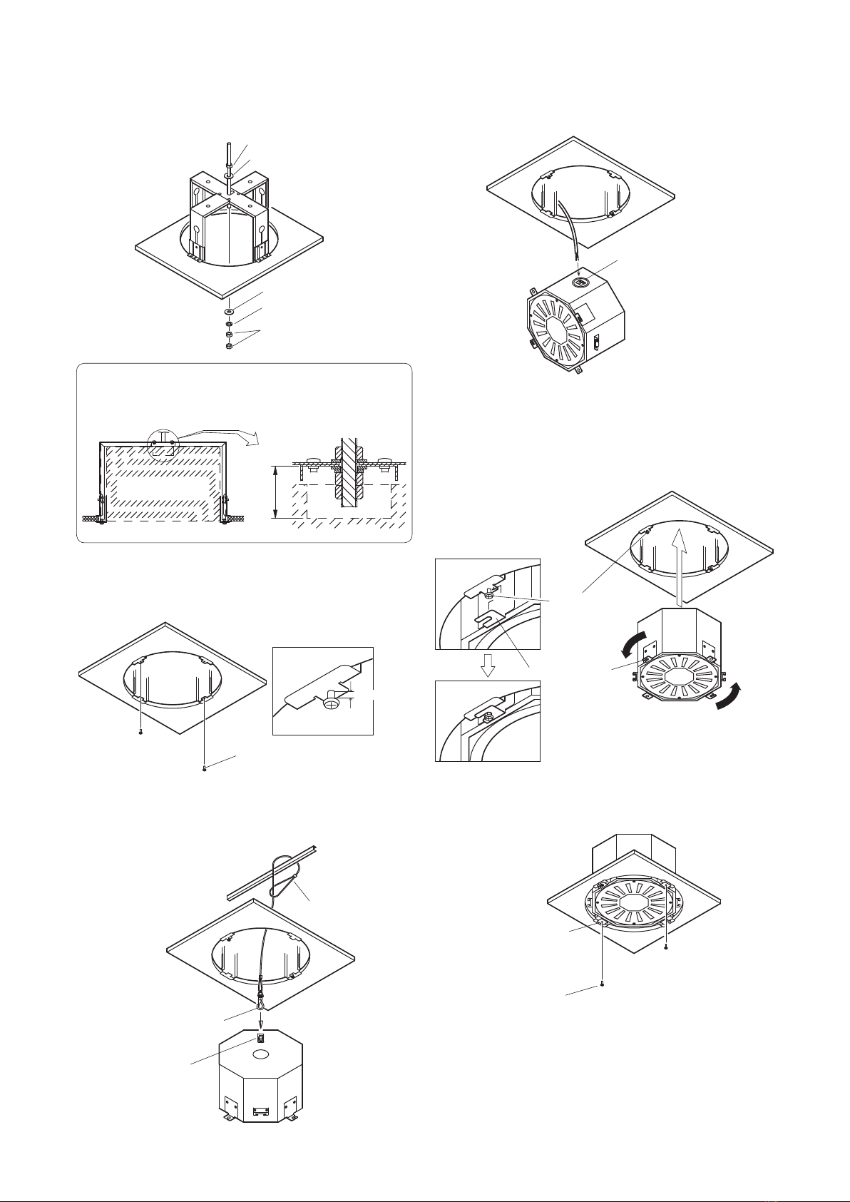
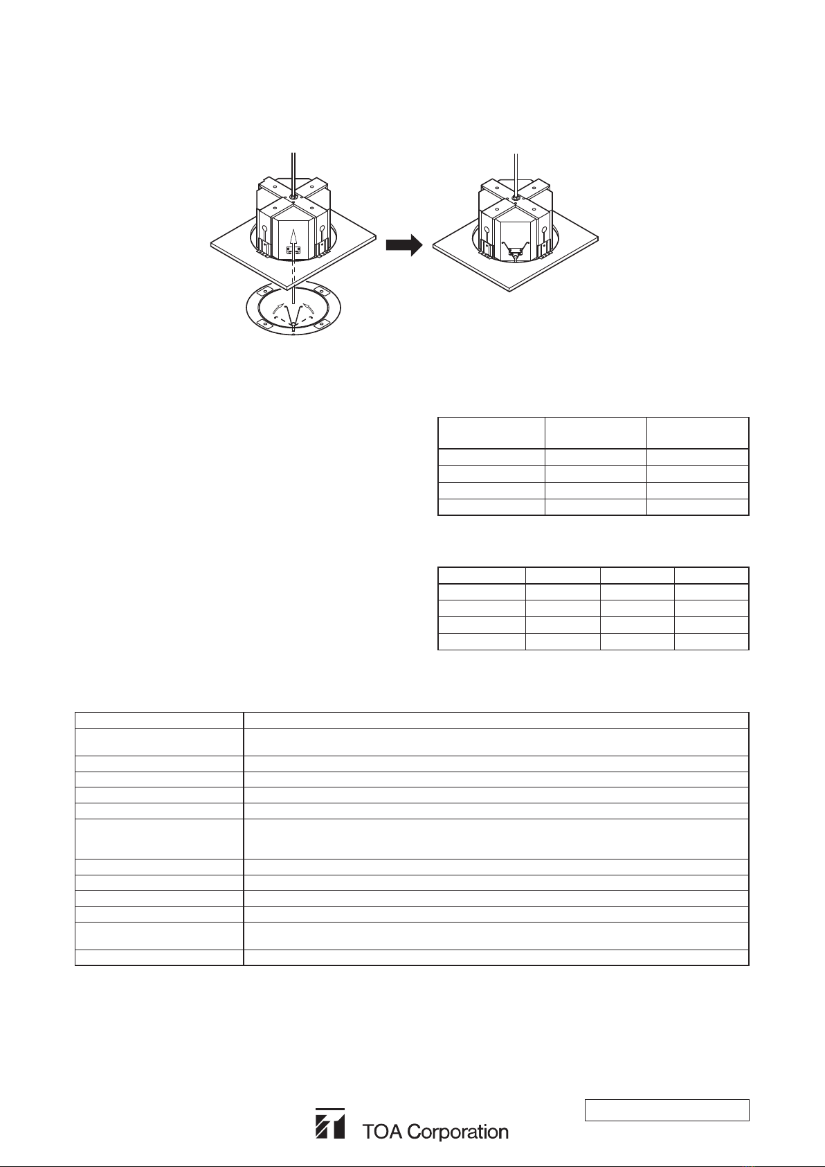
• A sliding retainer clip is designed to temporarily
hold the speaker in four places during installation
and service. Always be sure that the speaker is
further secured by the anchor bolt to ensure that
it does not accidentally fall and possibly result in
personalinjury.
• Use only the speaker’s specied front grille and
matching transformer. If any other front grille or
matchingtransformerisused,it coulddetach and
fall,resultinginpersonalinjuries.
When the speaker is in Use
• Should the following irregularity be found during
use, immediately switch off the power amplier
which is driving the speaker and contact your
nearest TOA dealer. Make no further attempt to
operate the speaker in this condition as this may
causereorelectricshock.
· If you detect smoke or a strange smell coming
from the speaker.
· Ifwateroranymetallicobjectgetsintothespeaker
· Ifthespeakerfalls,orthespeakercasebreaks
· Ifitismalfunctioning(notonesounds.)
When Installing the speaker
• Since installation requires specialized skills and
professional experience, always consult the
shop from where the unit was purchased before
beginning installation. If the speakershould fall, it
could result in electrical shocks or other personal
injuries.
When the speaker is in Use
• Do not operate the speaker for an extended
periodoftimewiththesounddistorting.Thisisan
indicationofamalfunction,whichinturncancause
heattogenerateandresultinare.
• Havethespeakerunitcheckedperiodicallybythe
shopfromwhereitwaspurchased.Failuretodoso
mayresultincorrosionordamagetothespeakeror
itsmountingbracketthatcouldcausethespeaker
tofall,possiblycausingpersonalinjury.
WARNING
Indicatesapotentiallyhazardoussituationwhich,
if mishandled, could result in death or serious
personalinjury.
WARNING
Indicatesapotentiallyhazardoussituationwhich,
ifmishandled,couldresultinmoderateorminor
personalinjury,and/orpropertydamage.
CAUTION
CAUTION
2. GENERAL DESCRIPTION
TheES-C0651isahighpowerceilingush-mountspeakerdesignedtobemountedtothemediumandhighceiling.

3. FEATURES
• Newly-developed,high-efciency25cmcoaxialspeakerwithhighpowerhandlingcapabilities.
• Compressiondriverwithaluminumdiaphragmassureshighpowerreproduction.
• Newcoaxialhorn(constantdirectivityof60°horizontalby60°vertical)assuresauniform,well-controlledpatternofhigh
frequencysounddispersion.
• Anchorbracketsupplied.
• Push-inspeakerconnectionandterminalsfacilitateinstallation.
4. NOMENCLATURE
[Speaker] [Anchor Bracket]
Safety wire mounting bracket
Blank panel
Anchor bolt mounting hole
Mounting tab B Mounting tab A Sliding bracket mounting slot
Mounting screw (M4x12)
Push-in terminals
Note :Theanchorbracketismountedtotheenclosure
whenunitissuppliedfromthefactory.
5. INSTALLATION PROCEDURE
1. Makea320mmdiameterholeintheceilingandsecure
theanchorboltinthepositionshowninthegure.Then
threadanuthalfwayupthelengthofthebolt.
2. Screwawingbolthalfwayintoeachoftheslidingretainer
clips,andleavetheboltstickingoutabout3mm.
3. Slide aplain washerovertheanchorbolt. Thent the
anchorbracketintotheceilingholeandinserttheanchor
boltintotheovalholeintheanchorbracket.
4. Attach the four sliding retainer clips to the legs of the
anchorbracketbyinsertingtheheadsofthewingbolts
intothecorrespondingslots,thenslidetheclipsdownto
grasptheceilingpanelbetweentheclipsandtheends
of the anchor bracket, then secure with the bolts.
Anchor bolt
Ceiling panel
Nut
About 170 mm
ø320 mm
Wing bolt
Sliding retainer clip
About 3 mm
Plain washer
Anchor bracket
Anchor bracket
Sliding retainer clip

5. Slideaplainwasherandaspringwasherontotheend
ofthe anchorbolt,then threadon twonuts. Secureby
clamping the anchor bracket tightly between the bolt’s
upperandlowernuts.
8. Connect the speaker cables to the push-in terminals
located on the side of the speaker. The terminals can
alsobeusedforbridgeconnection(parallelconnection)
of multiple speakers.
9. Push the speaker up in the ceiling hole and rotate it
counter-clockwise to catch the speaker’s mounting tabs
A on the speaker mounting screws, as shown in the
gure below. Then secure by tightening the mounting
screws.
10.SecuretwomountingtabsBaswellbytighteningthe
suppliedmountingscrews(M4x12).
Rotate the speaker until the mounting
screwscompletelytintothenotches
of Mounting tabs A.
6. Screwthesuppliedmountingscrews(M4x12)intothe
basesof theanchor bracketswith their headssticking
out approximately 3 mm.
7. Wrapasafetywireroundaheavy-dutyceilingbeamor
C channel, then connect the snap ring to the safety wire
mounting bracket.
Nut
Plain washer
Plain washer
Spring washer
Nuts (2)
Note
Takecarethattheanchorboltdoesnotprotrudemore
than32mmfromtheinsideoftheanchorbracket.
Speaker unit
Less than
32 mm
Mounting screw
About 3 mm
Safety wire
Safety wire
mounting bracket
Snap ring
Push-in terminals
Mounting screw
Mounting tab A
Mounting screw
Mounting tab B

URL:http://www.toa.jp/
133-01-00024-00
6. ABOUT THE COMBINATION WITH OPTIONAL EQUIPMENT
6.1. Attaching an Optional Front Grille FG-C0651
Squeezethetwospringsofthefrontgrilleandmountthemtotheircorrespondingspringcatchholderslocatedontheside
of the speaker.
Note :ForspecicationsofthefrontgrilleFG-C0651,refertotheinstructionmanualattachedtothefrontgrille.
6.2. Installing an Optional Matching Transformer MT-S0601
To install the MT-S0601 transformer in the speaker system,
removetheblankpanellocatedatthesideofthespeaker.For
theinstallationmethod,refertotheinstructionmanualattached
to the MT-S0601 transformer.
6.3. Low Frequency Equalization By Digital Signal Processors
Low frequency characteristics can be corrected using TOA’s
digitalsignalprocessor.Whenusingthespeakerincombination
withthedigitalsignalprocessor,thesettingsshowninthetable
atrightarerecommended.
The speaker complete with a front
grilleattachedbymeansofaspring.
MT-S0601
Primary terminal
Highimpedance
100 V line
Highimpedance
70 V line
83Ω
-
60 W
170Ω 60 W 30 W
330Ω 30 W 15 W
670Ω 15 W 7.5 W
TYPE Freq. Gain Q
HPF 40Hz
-
Q 0.500
PEQ 90Hz +10dB Q2.456
PEQ 180Hz
-
4dB Q 1.414
PEQ 630Hz +3dB Q 1.850
7. SPECIFICATIONS
Enclosure Type Sealedtype
PowerHandlingCapacity 180W(continuousprogram)
60W(continuouspinknoise)
NominalImpedance 8Ω
OutputSoundPressureLevel 96dB(1W,1m)
Frequency Response 80Hz–20kHz
CrossoverFrequency 2.5kHz
Speaker Coaxial speaker
Lowfrequency:25cmconespeaker
Highfrequency:CDhorn(60°x60°)pluscompressiondriver
InputTerminals Push-in terminals
AnchorBoltInstallation Anchorboltreceptacle(anchorbracket)attached.
CeilingHole Roundholewithdiameterof320mm
Enclosure Depth 200mm
Materials Enclosure:Wood(MediumdensityberorMDF)
Anchorbracket:Steelplate
Weight 6.8kg(includingananchorbracket)
Note: Thedesignandspecicationsaresubjecttochangewithoutnoticeforimprovement.
• Accessories
Slidingretainerclip ............................................................................................................ 4
Wingbolt(M4x8) ............................................................................................................... 4
Patternpapers(oneforroundholeandoneforanchorboltpositionsetting) ...................2
Safety wire ......................................................................................................................... 1
Table of contents
Other Toa Speakers manuals