Toledo V180E-US15 User manual

USER MANUAL
Electronic Lever &Knob
Manual del usuario
Mango &Pomo Electrónico

White Page
Keyless Electronic Lock
INSTALLATION INSTRUCTIONS
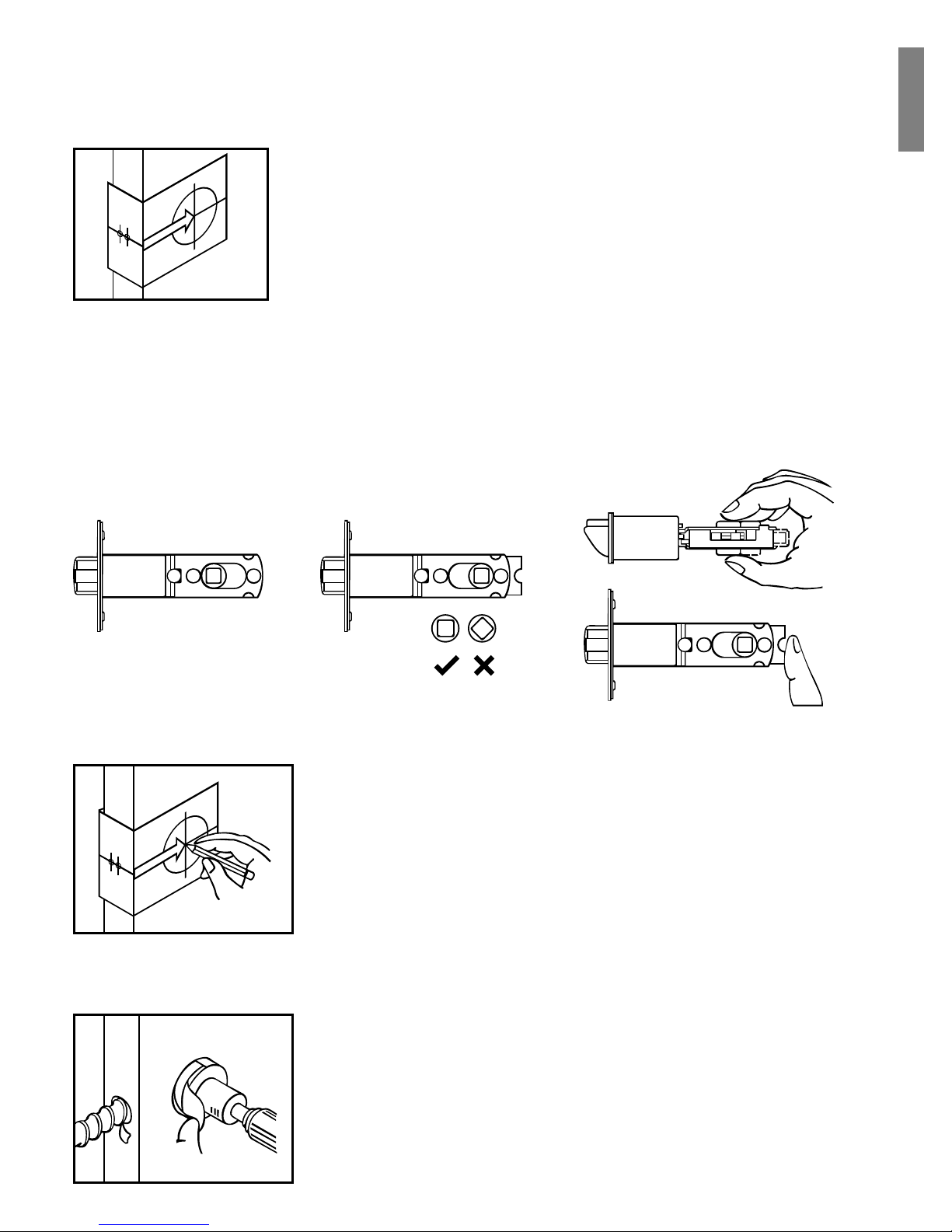
1. MARK THE DOOR WITH TEMPLATE
2. DRILL HOLES
The BACKSET is the distance between the center of
cross bore and edge bore of the door. Adjustable
latch fits both BACKSET of 2-3/8” (60mm) and 2-3/4”
(70mm). Please follow the steps shown below for
BACKSET adjustment.
a. The backset shown on the left is 60mm (2-3/8”).
b. Pull the cam toward right to extend the backset to 70mm (2-3/4”).
c. The backset shown in figure C is 70mm (2-3/4”). Pull the cam back to left
will return the backset to 60mm (2-3/8”).
Note: The shape of cam must be square.
abc
Select the height and backset as desired on the
boor face. Use the template as an indication to
the center of the circle on the door face and the
center of the door edge.
Using the marks as a guide to drill a hole
ø 2-1/8” (54mm) through the door face for the
lockset, then a hole of ø 1” (25mm) for latch.
English
4. INSTALL LATCH
a. Insert the latch and lay the faceplate against
the door edge. Use a pencil to mark it’s
perimeter, then take out the latch.
b. Chisel out the portion you have marked with
the pencil for about 4mm (5/32”) deep. Score
the area within the borders as clearly and
precisely as possible. Ensure the plate can
fit flush with the door edge surface.
c. Insert the latch and tighten it with screws.
Be sure the holes for thru-bolts (next to the
adjustable cam) should be horizontally aligned.
d. There is no necessary to chisel the door edge
for the faceplate installation if you use the
drive-in latch. You may install it into the edge
bore directly. Be sure the bevel face the outside
assembly.
3. IDENTIFY DOOR HANDLING
Face the door from outside. The door is left handed if the hinge is on the
left hand side of the door, whereas the door is right handed if the hinge
is on the right-hand side of the door.
Interior
Exterior
Left Handed Right Handed
Door Hinge

a. Half-close the door to lay the latchbolt against the door frame. Mark
the position of faceplate as an indication. Place the strike against the door
frame and mark it’s perimeter. Be sure the center of strike is perfectly
aligned with the center of faceplate.
b. Drill a ø 25.4mm (1”) hole with 13mm (1/2”) depth on the center of
strike outline. Then use the chisel to scrape out the door frame for 1.6mm
(1/16”) deep within your pencil mark. Ensure to chisel deep enough
to allow the strike lay flush with the frame surface.
c. Insert the strike and tighten it with screws.
Note: please use “tapping screws” for metal door.
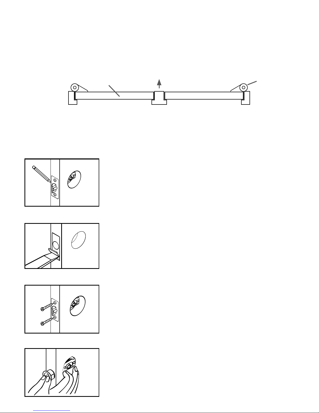
a. Place the leverset / knobset against keyless pad with tailpiece in vertical
position inserted through cam of the latch.
b. Pass the IC wire over the latch to the interior side of door.
Tailpiece
Outside Knob
Outside Lever
IC wire
Tailpiece must be turned
in vertical position
5. INSTALL STRIKE
6. INSTALL KEYLESS ASSEMBLY
12345
67890
12345
67890
12345
67890
7. INSTALL INSIDE MOUNTING PLATE
8. INSTALL RECEIVER MODULE
Mounting
Plate
IC Wire
Screws
a.
c.
Turn
Piece
Receiver
module
Battery
cover
wood screw
screws
Inside
Lever
Inside
Knob
b.
Pass th IC wire through the hole
on the mounting plate and hold
the mounting plate with screws.
If outside lock assembly is lopsided,
please loosen the screws to adjust
it’s position and tighten the screws
again.
a. Remove the battery cover (push it up and pull it out).
b. Connect the IC wire and ensure the turn piece is horizontal, so that the
tailpiece is able to be engaged with the inside lever / knob. Then attach
receiver module to the door with screws. It is optional to use the attached
wood screw. (wood screws are only for wood door)
c. Insert 4(AA) 1.5v alkaline batteries and put the battery cover back to the
receiver module.

a. Be sure the levers are unlocked. Insert the provided pin wrench into the
small hole on the neck of lever and apply pressure to depress the catch and
pull out the lever from the stem. Follow the same steps to remove interior
lever and exchange the position of inside and outside levers.
b. Remove the cylinder from lever and insert it into opposite lever. Then
install the levers and make sure the small hole on the neck of lever aligns
over the catch perfectly. Rotate the levers to see if it operates well.
9. CHANGE LEVER HANDLING
12345
67890
12345
67890
Cylinder

Programming Button
Programing Button is for entering codes, clearing errors and setting
functions.
Number Buttons
Input the user codes. Each user code is 4 to 10 digits in length.
Cylinder
Lock / Unlock the lockset from exterior.
Gasket
Prevent water permeating into lockset.
Battery Lid
Slide the lid to change the batteries.
Battery Holder
Holds four AA (1.5v) Alkaline batteries.
R. Button (Reset)
Restore defoult settings.
Turn- Button
Lock / Unlock the lockset from interior.
1
2
3
4
5
6
7
8
1
6
2
7890
345
1
2
3
4
6
7
8
5
Keyless Electronic Lock

Specification/Function
1.Power
6V, four AA (1.5V) Alkaline batteries.
2.Low Battery
2-1 The batteries should be changed immediately once you see button 1 flashes
in red and hear 10 rapid beep sounds when press programming button.
2-2 All settings are retained in the memory and will not be affected even
if the battery is completely dead.
2-3 The lock still can be operated by key even there is a power outage.
3.llluminated lndicator
3-1 Button 1 flashes in green once when successful operation.
3-2 Button 1 flashes in green twice when successful programming.
3-3 Button 1 flashes in red 3 times when there is an operation error.
3-4 Button 1 flashes in red 5 times when codes input error, the system will shut down
for system protection (refer to17).
3-5 Button 1 flashes in orange 3 times when system has been restored to default setting.
3-6 Button 1 flashes in orange slowly while in programming mode.
4.Audible lndicator
4-1 1 beep sound indicates a successful operation.
4-2 2 long beeps indicate a successful programming
4-3 3 beeps indicate an operation error.
4-4 3 long beeps indicate that system has been restored to default setting.
4-5 5 beeps when codes input error, the system will shut down for system protection.
(refer to 17)
4-6 10 rapid beeps indicate the power of battery is low.
5.Programming Code
5-1 The preset Programming Code is 0000. Please change it into new one when first
time operation.
5-2 Only one set of Programming Code for function setting.
5-3 Programming Code is only for function setting, you can not unlock the lockset
by entering Programming Code.
5-4 Programming Code is 4 to 10 digits in length.
5-5 Programming Code can be changed anytime if needed.

6.User Code
6-1 The preset user code is 1234.
Please delete it and create new one when first time operation.
6-2 Up to 6 sets of User Codes can be saved.
6-3 User Code is only for unlocking the lock, without programming function.
6-4 User Code is 4 to 10 digits in length.
6-5 User Code can be deleted or added anytime if needed.
7.Delete lndividual User Code
7-1 User Codes can be deleted individually. You can re-set the same number
as code even it’s deleted before.
7-2 Programming Code is needed when deleting lndividual User Code.
8.Delete All User Codes At Once
8-1 All the User codes can be deleted at once. You can still reset the same numbers
as codes even they are deleted before.
8-2 Auto-locking and Keypad locking function will be invalid after deleting all User
Codes and the lock can only be operated by key. These functions will be restored
when recreate new User Codes.
8-3 Programming Code is needed when deleting all User Codes.
9.Temporarily Disable All User Codes
9-1 Auto-locking and Keypad locking function will be invalid when User Codes
are temporarily disabled. The lock can only be operated by key during the time.
9-2 Repeat the programming steps again to restore the auto-locking, keypad locking
function and User Codes.
10.Create a Disposable User Code
10-1 Disposable User Code will be no longer valid once being used.
10-2 You can reset same number as Disposal User Code again.
10-3 Programming Code is needed when creating a Disposable User Code.
11.Restore Preset Factory Code
11-1 You can restore Preset Factory Code by pressing “R” button on the interior receiver
module when you forget Programming Code or you want to cancel all previous
setting.
11-2 After restore the Programming Code will be 0000. The User Code will be 1234 again.

12.Unlock the door
12-1 The lockset will be unlocked by key or by pressing the User Code on keypad from
outside or by the interior turn-button.
12-2 To unlock the door on the keypad, enter the User Code and then press the
Programming/Enter button.
13.Lock the door
The lockset will be locked by key or by pressing the Programming Button on keypad
from outside or by the interior turn-button.
14.To Activate / Deactivate Auto-Locking Function
14-1 The lockset will automatically lock itself within 10 to 99 seconds when this function
is programmed.
14-2 This function is not preset at the beginning. It can be set if needed.
14-3 The preset delay-time is 30 seconds, you can adjust the time as you want.
14-4 Please repeat the same programming steps to cancel Auto-Locking function
when needed.
15.Toggle Mute On/Off
15-1 You will hear beep sounds when pressing keypad, programming or operating
errors. lt can be turned off if needed.
15-2 LED lllumination is still functioning when it is in mute. Therefore will not be any
warning alarm, we suggest not to mute the beeper if it’s not necessary.
15-3 Motor operating sound cannot be muted.
16.Code Protection Function
The system will shut down if entering unauthorized codes over 5 times.
The System will be operative again after 45 sec.
17.lllumination
The LED Keypad will light up when pressing any button for ease of operating in the dark.

Pass Code & Function Set up
1. It should be under unlock status while programming.
2. Please change default Programming Code (0000) and User Code (1234) before
function set up when first time operation base on safety consideration.
3. LED flashes orange slowly while programming.
LED flashes green twice with 2 long beeps when correct input.
LED flashes red 3 times with 3 beeps when incorrect input. (You need to wait for 6
seconds or press programming button when incorrect input. then the system will be
operative again.)
4. Each programming step should be done within 6 seconds.
5. You can lock and unlock this product by either key or keypad.
Please refer to the following programming table for function set up.
Remark
1. We recommend to use alkaline battery in order to stabilize the power supply.
2. Do not mix alkaline battery with regular zinc-carbon ones or mixed brands.
3. Do not use any chemical liquid or lubricating oil with additives to clean the lock
body, it will damage the surface or even the mainboard.
4. lf there is any problem of the product, please contact your local retailer and send
back the product to us for repair or replacement.
Function Programming
Enter PC
Enter PC
Enter PC
Enter PC
Enter PC
Remark:
Up to 6 sets of User Code can be saved. User Code should be from 4 to 10 digits in length.
Remark:
Auto locking and keypad locking function will be invalid when User Codes are deleted.
The lock can only be operated by key during the time.
Remark:
The preset delay-time is 30 seconds, you can change the time by following instruction.
Repeat the steps to cancel the Auto-locking function.
Enter
New UC
Enter
New PC
Enter the
UC you
want to
delete
Add new User Code
Delete an existing User Code
Change Programming Code
Delete all User Code at once
Toggle Autolock on / off
Programing Code (PC)
User Code (UC)
TOLEDO
TOLEDO
TOLEDO
TOLEDO
TOLEDO
TOLEDO
TOLEDO
TOLEDO
TOLEDO
TOLEDO
TOLEDO
TOLEDO
TOLEDO
1
2
4
3
5
Enter PC
Enter PC
Enter PC
Enter PC
Press
Remark: 10-99 seconds delay-time available.
Remark: Repeat same steps to turn beeper On/Off. Led illumination is still functionimg
when it’s in mute. But there will be no warming alarm.
Remark: Auto-locking and Keypad locking function will be invalid when User Codes are
disabled. The lock can only be operated by key during the time. Repeat the steps to enable
the User Codes again.
Remark: Disposable code will be no longer walid once being used.
Remark: Press ‘‘R’’ button for over 5 seconds.
The programming will complete after you hear 3 long beeps
Set Autolock time delay
Toggle Mute on / off
Enable / Disable all User Code
Create a disposable User Code
Restore all preset lock settings
TOLEDO
TOLEDO
TOLEDO
TOLEDO
TOLEDO
TOLEDO
TOLEDO
TOLEDO
6
7
8
9
R
Enter
Seconds
(10-99)
Enter new
disposable
UC
TOLEDO
TOLEDO
Programing Code (PC)
User Code (UC)
Function Programming
ø 54mm (2-1/8”)
Mark ø 1” (25mm) hole
at center of door edge.
Fit here on door edge
FOR BACKSET 70mm (2-3/4”)
45
1-3/4” 1-9/16” 1-3/8”
40
TEMPLATE
35
FOR BACKSET 60mm (2-3/8”)

White Page

Cerradura Electrónica Keyless
Instrucciones para instalación
1. Marque la puerta con el patrón
2. Taladre los huecos
El picaporte ajustable le sirve a ambas profundidades
de 2-3/8” (60mm) y 2-3/4” (70mm). Siga los pasos
ilustrados adelante para los ajustes de profundidad.
a. El picaporte mostrado a la izquierda es de 60mm (2-3/8”).
b. Hale la leva hacia la derecha para extender el “backset” a 70mm (2-3/4”).
c. El backset mostrado en la figura C es de 70mm (2-3/4”). Empuje la leva
hacia la izquierda para regresarla al “backset” de 60mm (2-3/8”).
Nota: La forma de la leva debe estar cuadrada.
abc
Seleccione a su gusto la altura y la profundidad
en el frente de la puerta. Use el patrón como
guía para marcar el centro del círculo en el
frente de la puerta y el centro en el borde
de la puerta donde se instalará el picaporte.
Utilice las marcas como guía para taladrar
el hueco de ø 2-1/8” (54mm) en el frente de
la puerta. Luego utilice las marcas como guía
y taladre el hueco de ø 1” (25.4mm) para el
picaporte.
Español

4. Instale el picaporte
a. Introduzca el picaporte y asegure que esté
paralelo con el frente de la puerta. Marque
con un lápiz una línea alrededor de la placa
de metal del picaporte, luego retire el picaporte.
b. Con un formón, haga un corte profundo
de 5/32” (4mm) dejándose llevar por la línea
que marcó. Verifique que la placa de metal
esté alineada con el borde de la puerta.
c. Introduzca el picaporte y ajuste con los
tornillos. Asegúrese que los huecos de los
tornillos pasantes (quedan al lado de la leva)
estén alineados horizontalmente.
d.Si utiliza el picaporte especial no necesita
cortar la madera de la puerta con el formón.
Puede ser instalado directamente a la puerta.
Asegure que el biselado quede hacia afuera.
3. Identifique el manejo de la puerta
Acomódese de frente a la puerta desde el exterior de ésta. La puerta
es manejada a la izquierda si el gozne está en el lado izquierdo
de la puerta. Si el gozne está en el lado derecho de la puerta entonces
la puerta es manejada a la derecha.
Interior
Exterior
Lado izquierdo Lado derecho
Puerta Gozne
a. Para identificar el centro del pasador: Cierre la puerta, en la base de la
placa de metal marque una línea horizontal en el pasador. Asegúrese que
el centro de la placa frontal y el centro del pasador estén alineados. Utilice
las marcas como guías fuera del pasador.
b. Utilice las marcas como guía y taladre el hueco de 1” (25.4mm) para
el picaporte. Con el formón haga un corte en la madera de 1/16” (1.6mm)
alrededor del pasador que permita que el pasador y el marco de la puerta
estén alineados.
c. Introduzca el pasador y ajuste con los tornillos.
Nota: Para puertas de metal use tornillos auto roscable.
a. Coloque el mango o el pomo en contra de los botones con la cola
en posición vertical atravesando la leva del picaporte.
b. Pase el cable IC atravez del picaporte hacia el lado interior de la puerta.
Cola
Pomo exterior
Mango
exterior
Cable IC
La cola debe estar
en posición vertical
5. Instale el pasador
6. Instale la maquinaria del sistema Keyless
12345
67890
12345
67890
12345
67890
7. Instale el interior de la placa de montura
8. Instale el módulo recibidor
Placa de
montura
Cable IC
Tornillos
a.
c.
Pieza
giratoria Módulo
recibidor
Tapa de
batería Tornillos
para
madera
Tornillos
Mango
interior
Pomo
interior
b.
Pase el cable IC a través del hueco
de cable de la placa base. Acomode
la placa de montura con los tornillos.
Si el montaje de afuera de la cerradura
está virado, suelte los tornillos para
arreglar la posición y vuelva a ajustar
los tornillos.
a. Remueva la tapa de la batería. (empuje hacia arriba y hale hacia fuera).
b. Conecte el cable IC y asegure que la pieza giratoria esté en posición
horizontal, para que la cola “tailpiece” conecte adentro de el mango
o el pomo. Luego sujete el módulo recibidor a la puerta con los tornillos.
(los tornillos de madera sólo se usan para puertas de madera).
c. Introduzca 4 baterías alcalina AA (1.5V) y tape la batería
del módulo recibidor.
Table of contents
Languages:
Other Toledo Door Lock manuals


Popular Door Lock manuals by other brands

Assa Abloy
Assa Abloy Yale nexTouch Installation and programming instructions

Vicenza Designs
Vicenza Designs DHPA8000 Instructions for installation

Visionis
Visionis VIS-600D-LED instructions

uhlmann & zacher
uhlmann & zacher CX2162 Operating and assembly manual

Dorma
Dorma RTS Series quick start guide

Burg Wächter
Burg Wächter TSE Premium operating instructions


