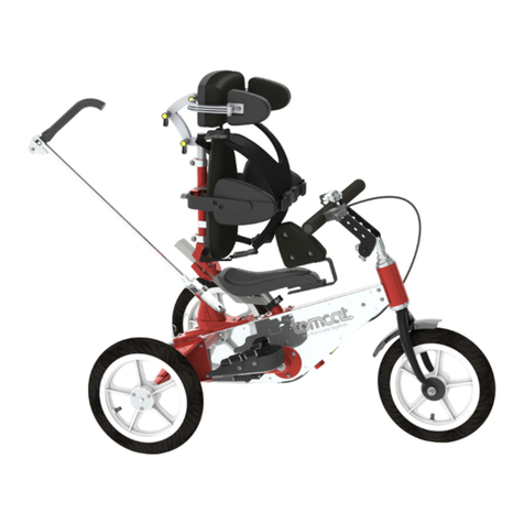
Tomcat BULLET User manual

WWW.TOMCATUK.ORG
T O M C A T B U L L E T & A R R O W
R O T O R M A N U A L U K
INVEN TIO NS WIT H A SO CIA L P URP OSE

Standard cycle components apart, this
product has been designed and
manufactured at our Gloucester factory
and what we do not manufacture
ourselves is supplied or manufactured
by other UK companies, so we thank you
for supporting British industry by
buying this very British product.
CUSTOMER SERVICE: We are proud to offer our
customers the very best in product aftercare
because we understand that things can change, and
your vehicle may be your lifeline. Our customer
service and spares department is open 6 days a
week, between 10 am and 5 pm, Monday to
Saturday, for technical advice, spare parts, service,
and general assistance throughout the life of your
product.
Because your trike is entirely made in England by
Tomcat, and because we have UK wide coverage for
our products, if problems do occur you have the
peace of mind of knowing that we can deal with your
difficulty in the quickest way possible, be that advice
over the telephone, an onsite visit, local authorised
repair or return to our Gloucester factory.
We hope you have many years of enjoyment
and usefulness from your Tomcat Bullet &
Arrow Rotor.
| ROT OR MAN UAL PA GE | 1
Life changing
TRIKES
THAN K YOU F O R SU P P ORTI N G
BRIT I S H IN D U STRY B Y CH O O SING
THE F A NTAS T I C TO M C AT B U L LET
ROTO R AND A R ROW R O TOR F R OM
TOMC A T SNI L TD, A “QUE E N S
AWAR D FOR E N TERP R I SE I N
INNO V A TION ” , WIN N I NG C O M PANY .
Dear Customer,

Life changing
TRIKES
Index to Sections.
1. General Safety instructions for
users.
• Observe your country's highway
regulation at all times.
• Always wear a helmet and suitable
protective clothing.
• Use all safety devices provided.
• Follow all instruction and warnings in
this manual and on the vehicle and
ensure all riders are conversant with all
safety instructions and warnings before
they use the vehicle.
• Do not carry passengers or allow
others to stand on the rear axle or
basket, etc.
• Use the park brake when mounting or
dismounting, or when the vehicle is
unsupervised.
• Do not ride over kerbs (except "drop
kerbs") or any other hazards that may
destabilise the vehicle.
• Do not use off-road, on steep inclines,
heavy cambers or sloping or uneven
ground.
• Take extra care in snow, ice or other
adverse weather conditions.
Before each use.
• Ensure lights, reflectors, flags and
warning devices are in good working
order.
| RO TOR MA NUA L PA GE | 2
Physio & Fun
TRIKES

Check tyre condition and maintain correct tyre pressure as printed on the tyre
wall.
• Check you have enough power for your journey and your charger is disconnected.
• Test braking and steering functions and ensure all removable components
(wheels, seat, divisible frame mechanisms, etc) are correctly assembled in
accordance with instructions in this manual.
• Ensure all quick release features are interlocked where interlocks are provided,
and that all interlocks are in good working order.
| ROT OR MAN UAL PA GE | 3

2. General Information
This information relates to base models. Certain accessories may change these
parameters.
Overall Dimensions/measurements for the Tomcat Bullet Rotor (assembled)
• O/A Length. 190cm
• O/A Width 74cm
• O/A Height 125cm
• Overall Weight 22kg
• Overall weight with power assist 26.5g
• Max user weight, SWA 120kg
• Rider Height Range Size 2 135cm to 188cm
• Max cargo weight (basket) 5kg
• Hand Crank Length 170/150mm
• Motor Type Ansmann Brushless FM6/250W/36V
• Battery Li-Ion 9000mAh/36V output.
• Charger Lithium Ion Charger CC/CV method
Overall Dimensions/measurements for the Tomcat Arrow Rotor (assembled)
• O/A Length. 178cm
• O/A Width 74cm
• O/A Height 125cm
• Overall Weight 20kg
• Overall weight with power assist 26.5g
• Max user weight, SWA 120kg
• Rider Height Range Size 2 135cm to 188cm
• Max cargo weight (basket) 5kg
• Hand Crank Length 170/150mm
• Motor Type Ansmann Brushless FM6/250W/36V
• Battery Li-Ion 9000mAh/36V output.
• Charger Lithium Ion Charger CC/CV method
| ROT OR MAN UAL PA GE | 4

3. Manufacture.
The product is designed and manufactured in the United Kingdom in compliance
with EEC Directive 93/42, by Tomcat SNI Ltd.
Unit 13.7, The Gloucester Business Park
Hucclecote
Gloucester
GL3 4AA
Tel: (+44) 01452 616900
Email info@tomcatuk.org
www. www.tomcatuk.org
. User Adjustment.
Each rider will require a slightly different setup to get the best from themselves
and the machine, however, there are just a few simple rules to follow to achieve a
comfortable riding position.
• See the User Instructions for information on how to make the following
adjustments to your machine.
• Firstly, sit on the vehicle and roughly set your seat at a comfortable distance
from the hand cranks. You should be neither stretched nor cramped with the hand
cranks at 6 and 12-o-clock.
• Now set the height of the hand cranks so they are neither too high or too low in
the 6 and 12-o-clock position.
• Now set your footrests to a comfortable position in which your hands are clear
of your knees when the hand cranks rotate. As a guide, your thighs should be
level or slightly downhill. If you are exceptionally tall "Drop Footrest Brackets"
from your supplier may be necessary.
• Now fine-tune your seat position and crank height by selecting the lowest gear
and rotating the hand cranks. Hand cranking is most productive when both the
spine and arms (and in particular, the elbows) are working together. At 9-o-
clock, the elbows should be at full stretch and your spine bent forward at the
shoulders, whilst at 3-o-clock your elbows should be well contracted and your
spine bent slightly backward. In this way, you will be using your whole upper body
to propel yourself along.
• For the above reason, it is never a good idea to have too high a backrest as this
will inhibit your ability to bend your spine backwards.
| ROT OR MAN UAL PA GE | 5

• If you find, after following the above process that you are excessively
stretched at 9-o-clock and 3-o-clock, your arm length or flexibility might be such
that shorter cranks are required to be comfortable. However, try the hand
cranks you are supplied with for at least two weeks to allow your body to adjust
to the new movement regime before raising the matter with your supplier. You
should also bear in mind that shorter hand cranks means you will develop lower
torque which in turn means higher effort when not using your power assist (if
fitted). In general, you will benefit from using the longest hand cranks possible.
• Ensure all clamps are firmly closed and the footrests and crank head are fully
unmoveable before riding off.
5. Standard Features
The Rotor is distributed in England by Tomcat SNI Ltd and its distributors and
agents with the following standard features. Other features and accessories
for support and convenience are available.
• Telescopic footrest adjustment
• Sliding Seat
• Swivel Seat
• Upholstered, water-resistant seat cushions
• Flag, lights, front and rear, and a bell
• "Height and Reach" adjustable, Hand Cranks
• 8 Speed Nexus Geared Hub
• Front Calliper and Rear Disc Brakes
• Motor, 9Ah Battery and Li-ion Charger
Optional Features
• Hand and Foot Drive
• Transportable Frame
• Removable mudguards and rear wheels.
• Removable Seat
• Shopping Basket and removable carrier.
| RO TOR MA NUA L PA GE | 6

6. User Instructions and Information.
6A Rotor Crank Head Adjustment
The crank head height is adjustable within the fork assembly for the ergonomic
adjustment of user setup. To adjust the height, slacken the clamp lever or screw
and move the crank head to the desired position. Re-clamp firmly when correctly
adjusted. The chain drive will automatically adjust itself to the new position and
no adjustment of the chain tension device is normally required.
Refer to Maintenance section and Fig 1 for instructions on chain tension.
| ROT OR MAN UAL PA GE | 7

6B Telescopic Footrest adjustment.
The Telescopic Footrest system provides easy adjustment of the users foot
position. If assistance is provided by a third part, adjustment can be carried out
with the rider seated. Adjustment is best done in conjunction with, or after
adjustment of the seating position. See sliding seat and Rotor Crank Head height
adjustment).
To adjust the Telescopic Footrests, slacken the camlock clamp. Rotate the knob
situated on the left side of the frame (beneath the seat) until the correct leg
length position is achieved.
Fully close the camlock so the handle is generally flush with the frame as
shown.Adjust the Camlock if necessary by rotating the thumbwheel clockwise to
tighten and vice versa to slacken. When adjusted satisfactorily, tighten the
clamp firmly.
Using the vehicle without a closed and properly adjusted clamp may cause damage
to the clamp or crank mechanism.
6C Sliding Seat.
The sliding seat has a smooth sliding front to back movement of 120mm. It is
used in conjunction with the adjustable handlebars to achieve a comfortable arm
"reach" for the user. To adjust the seat position, pull on the locking knob
beneath the left side of the seat and whilst holding the knob out, move the seat
to its desired position. Release the knob and check that it has relocked where
required.
| ROT OR MAN UAL PA GE | 8

| ROT OR MAN UAL PA GE 9
6D Swivel seat.
The swivel seat is an aid to getting on and off the vehicle with greater safety. It
has three self locking positions, Left, Right and Central. The rider normally
accesses from the pedestrian side of the road and when seated, rotates the seat
to the central position, passing their leg over the frame as they do so.
The seat is operated remotely by a small trigger lever. This can be mounted in a
variety of positions depending upon model and optional features. Operating the
trigger will release the latch and allow the seat to turn.
6E Water resistant cushions.
Seat and backrest cushions are covered in a nylon coated polyurethane material
that is impervious to liquids so liquids falling on the seat will not be absorbed by
the cushion cover or inner foam cushion . If the seat should become wet or need
cleaning, it can be dried with towels and hygienically cleaned with mild household
detergents for almost immediate re-use. However, it should not be pressure
washed, or unnecessarily or continuously exposed to the elements as this may
encourage mould to form between the cushion and back-plate.
6F 8 speed Shimano Nexus geared hub.
The vehicle is fitted with a Shimano Nexus 8 speed hub. It is good practice with
all hub drives not to change gear under load, whilst pedalling hard, or uphill.
Always "coast when changing gears. After a short bedding in period, the gear
settings may change slightly. Check and adjust if necessary with reference to
the Shimano online instruction video which can be viewed by right clicking on the
link below fand following the hyperlink.
Important note. Kinking of the gear change cable, or rerouting of the gear
change cable from that supplied, may adversely alter the gear settings and may
cause hub damage. Always check the gear settings are correct after snagging the
cable and adjust as necessary.

https://www.google.com/search?
q=shimano+nexus+8+speed+adjustment&rlz=1C1EODB_enGB527GB572&oq=shim
ano+nexus+8+speed&aqs=chrome.2.69i57j0l5.14421j0j8&sourceid=chrome&ie=U
TF-8#kpvalbx=_73lWXffiA-6L1fAPgc-iyA416
In accordance with Shimano recommendations, Check regularly that when 4th gear
is selected, the two yellow line coincide. Adjust if necessary with the adjuster on
the gear changer as directed.
If slippage is detected in gear five, check and adjust the alignment immediately
as this indicates poor hub adjustment. Continued use may cause serious damage.
6G Differential Drive.
The vehicle is fitted with a brake differential hub to both rear. This ensures
smooth and even braking to both rear wheels. The Differential Drive requires no
maintenance and is not user-serviceable.
6H Brakes.
The vehicle has front calliper and rear disc brake. They are selected and paired
to ensure balanced braking under normal conditions, however, adverse weather
conditions such as greasy road surfaces, rain, ice and snow can greatly reduce
braking performance. Take greater care in poor conditions.
The front calliper brake requires occasional adjustment and service to ensure
best performance. See Maintenance section for Instructions on calliper brake
servicing.
6J Power-Assist Motor, Battery and Charger.
There are no user-serviceable parts to the motor, battery or charger.
Battery care.
• Ensure the battery is fully charged before first use.
• After charging, the charging socket must be covered with the sealing plug to
prevent water ingress and corrosion.
• Recharge the battery when the battery pack has been out of service for 12
weeks to avoid damage to the battery.
• To check the battery charge level, press the button on the battery pack, next to
the indicator. The remaining battery capacity will be displayed by four LED
lights. A repeater battery condition display is also provided on the power control
module.
• Turn the main switch OFF after use to avoid continued discharge of the battery
pack.
• Recharge the battery after riding to recover operational readiness.
• Do not exceed the permitted user and cargo load of the vehicle.
| ROT OR MAN UAL PA GE |10

Display Controller
The display comprises a battery condition display, plus and minus power output
buttons with power level indication and a "soft start" button.
• The battery display automatically lights when the battery main switch is turned
on and indicates the remaining battery capacity with four LED diodes.
• Pressing the "plus" or "minus" buttons will raise or lower the delivered battery
power in 6 stages indicated by three solid or flashing LED diodes, i.e. 1 solid =
power level 1, 1 flashing = power level 2 and so on. With no power LED's lit, the
power is off. Press the "plus" button to return to power level 1. Switch off at
the main switch after use.
• Pressing the "A" button will engage start power without the need to turn the
crank arms. This starting aid is limited to 6kph and should not be used for
prolonged periods.
7. General Product Care.
• Keep the product clean.
·Store is in a dry, moisture free environment. Do not leave exposed to the
elements for prolonged periods of time, for example under plastic sheeting.
·Do not re-route any mechanical control cables, particularly gear cables. This will
alter brake and gear-hub settings.
·Keep the battery charged in accordance with the above instructions.
·Do not pressure wash electrical wires or components.
·Keep the tyres inflated to the pressure stated on the tyre wall. Do not exceed
this pressure.
·Lubricate all chains with light oil monthly and when laying up at season's end.
·Protect all metal parts with a light spray oil at season's end.
·Do not use the vehicle if any parts are loose or do not work properly. Investigate
and remedy before re-use.
·Check all safety devices at the beginning of each journey. Do not use the vehicle
if any are defective.
| ROT OR MAN UAL PA GE | 1 1

Maintenance and Service
8E Chains.
Monthly when in use and at layup, lubricate all chains with cycle chain oil.
Chain Drive Adjustment.
The chain drive comprises hand cranks connected by a 3/32" chain drive to the
Shimano Nexus Inter 8 Hub by 3/32 chain that passes over two jockey pulleys on
the "non-driving" run of the chain, one fixed, the other sliding with the hand
crank height adjustment. The pulleys cause the chain to follow a zig-zag route
that automatically adjusts the chain when the hand cranks are moved. However,
as the components bed in, the chain may become slack and need its tension
adjusted.
| ROT OR MAN UAL PA GE | 1 2
To adjust chain tension, Slacken the "Chain Tension Screw", lock nut, and turn the
"Chain tension Screw" clockwise to tension the chain and anti clockwise to
slacken. The tension is correct when approximately 2cm of movement is possible,
mid distance on the run of chain between the fixed jockey pulley and the Shimano
Hub. Retighten the locknut after adjustment.

8F Calliper Brake.
Periodically check the thickness of the brake pad and replace when the pad is less
than 3mm. Ensure the pads make full surface contact with the wheel rim and
does not rub the tyre. Adjust the pad position if necessary.
For efficient braking, set the calliper up so that there is an even gap of 1.5 -
2mm between each pad and the wheel rim in the following manner.
• Push the right hand pad fully against the rim and adjust the left pad with the
screw adjuster to achieve 3-4mm of clearance between pad and rim.
• Release the right pad and operate the brake several times. If either pad is
touching the wheel, slacken the securing nut, centralise the calliper assembly,
then retighten the nut.
| ROT OR MAN UAL PA GE | 1 3
8G 8 Speed Shimano Nexus Hub
Right click on the following link and click "open hyperlink" to view Shimano
adjustment instructions for the Shimano Nexus Inter 8 hub.
https://www.google.com/search?
q=shimano+nexus+8+speed+adjustment&rlz=1C1EODB_enGB527GB572&oq=shim
ano+nexus+8+speed&aqs=chrome.2.69i57j0l5.14421j0j8&sourceid=chrome&ie=U
TF-8#kpvalbx=_73lWXffiA-6L1fAPgc-iyA416
8H Sturmey Archer Front Drum Brake.
Right click on the following link and click "open hyperlink" to view Sturmey archer
adjustment instructions for the Sturmey 70mm Hub brake.
http://www.sturmey-archer.com/files/catalog/files/172/MANUAL%20-
%20DRUM%20BRAKES%20HUBS.pdf

8J Promax Rear Brake Adjustment.
The Promax Disc brake calliper is of the fixed and moving anvil type. Each
supports a brake pad which are arranged either side of the disc. When the brake
wire is pulled by the brake lever, the moving anvil and thus the pads are forced
against the rotating disc causing the vehicle to slow or stop.
To set up the calliper, it is first necessary to set the moving anvil (and its brake
pad) in close contact with the disc so that the slightest movement causes the pad
to press against the disc. The calliper is then locked in position, the fixed anvil
adjusted, and finally, the brake cable adjusted to suit. Proceed as follows.
• Slacken the calliper alignment screws (Promax screws "F") until the body of the
calliper slides freely (approx 1/2 turn)
• Slacken the fixed anvil setscrew by two turns.
• Tighten the Adjusting nut until the fixed anvil tightens firmly but not tightly
against the disc.
• Tighten the calliper alignment screws.
• Slacken the fixed anvil by two full turns.
• Spin the disc to ensure the moving pad is not bearing too heavily on the disc. a
slight rubbing sound or feel is normal providing it is not slowing the disc.
• Tighten the fixed anvil with the adjuster nut so that the pad is as close as
possible to the disc without slowing the disc. A slight rubbing sound or feel is
normal providing it is not slowing the disc.
• Tighten the setscrew very lightly to lock the adjuster nut in place.
• Set the Cable Adjuster and locknut at minimum protrusion from the calliper.
• Pull the cable to remove all slack in the mechanism and clamp it to the arm.
• Operate the brake lever and observe any movement that occurs before the arm
moves. If movement is detected, adjust with the adjuster and locknut or reclamp
the wire.
• The brake is now ready for use.
| ROT OR MAN UAL PA GE | 1 4

Repeat this process when braking efficiency deteriorates, the pads become worn,
or when the disc visibly buckles when the brake is applied.
When it becomes necessary to replace the pads, follow the Promax instructions
below. It will be necessary to remove the calliper and follow the above procedure
during reassembly and setup. If in doubt, consult a competent cycle technician.
| ROT OR MAN UAL PA GE | 1 5

| ROT OR MAN UAL PA GE | 1 6

Warranty
Thank you for purchasing this Tomcat SNI Ltd product.
This limited warranty applies to the physical goods, and only the physical goods,
purchased from Tomcat SNI Ltd or through one of its authorised dealers.
1. What does this limited warranty cover?
• This Limited Warranty covers any defects in materials or workmanship under normal
use during the warranty period.
• During the warranty period, Tomcat SNI Ltd will repair and replace, at no charge,
products, or parts of products that prove defective because of improper material or
workmanship under normal use and maintenance.
2. What we will do to correct the problems?
• Tomcat will either repair or replace the Product at no charge, using new or
refurbished replacement parts.
• At our discretion, we may decide to refund the price of the product, which must be
returned in full in its original packaging or in packaging authorised by us.
How long does the coverage last?
• The warranty period for physical goods purchased from Tomcat SNI Ltd or from
Tomcat SNI Ltd through its authorised dealer, is two years from the date of purchase
and five years for the product frame, excluding any attachments.
• A replacement Physical Good or part assumes the remaining warranty of the original
Physical Good or part from the date of purchase.
3. What does this warranty not cover?
• This Limited warranty does not cover any problems that are caused by:
• Conditions, malfunctions or damage not resulting from defects in materials or
workmanship, for example:
• Damage of a Product or part resulting from negligence or misuse.
• Damage of a product resulting from unauthorised modification of the product.
• Damage caused by natural disaster.
• The cost of returning the Goods under this warranty
• Theft or loss of the product.
4. What do you have to do?
• To obtain warranty service, you must first contact us, (or in the case of purchase
through one of our authorised dealers, your dealer) to determine the problem and the
most appropriate solution for you.
• If the return of the product is agreed, it must be returned in its original packaging.
• You will need an RMA (Return Merchants Authorisation) from Tomcat SNI Ltd or your
dealer.
• All documents and accessories shipped with the product must be returned if required
by Tomcat SNI Ltd or its dealer.
| SIL VER BU LLE T & AR ROW PA GE | 1 7
This manual suits for next models
1
Table of contents
Other Tomcat Bicycle manuals

