INTENSEcycles TRACER CARBON User manual
user manual TRACER CARBON

introduction / registration 2
frame features / component spec 4
Geometry 5
exploded view and b.o.m. 6
Assembly 8
torque chart 13
setup 14
maintenance 18
AT INTENSE, WE HAVE ONE GOAL - TO PROVIDE THE RIDE OF YOUR LIFE //
Our team of designers, engineers and product experts are focused on one thing every
day: your experience on the bike. We build bikes that are as thrilling to look at as they
are to ride, and we build them for the select few of you who understand the difference
and refuse to settle for anything else.
From the early days of Intense, when founder Jeff Steber worked alone in his garage to
today, where a crew of talented people work in a Temecula, CA factory, Intense has been
a brand built on passion by forward thinkers who, even today, love nothing more than
to throw a leg over a sweet bike and head out for a rip. We’re so glad you’ve joined us.
Welcome to Intense, enjoy your experience.
THE TRACER CARBON //
For the hardcore Enduro rider, the Tracer Carbon is built with a short rear end for
quick maneuvers and a long front end with a slack, 65.5 degree head angle to keep
things stable. 165mm of rear wheel travel on a stable pedaling platform gets you up
the hills easily and still allows for big hits on the way down. No corners were cut in
designing the easily serviceable pivots and lightweight carbon chassis but who needs
to cut corners when you’re on the fastest rig on the trail.
registration
WWW.INTENSECYCLES.COM/WARRANTY-CARD/
contact customer service
cs@intensecycles.com
951-296-9596
Welcome to
the family
2// tracer carbon user manual INTENSE CYCLES // 3
4// tracer carbon user manual INTENSE CYCLES // 5
frame
features /
spec
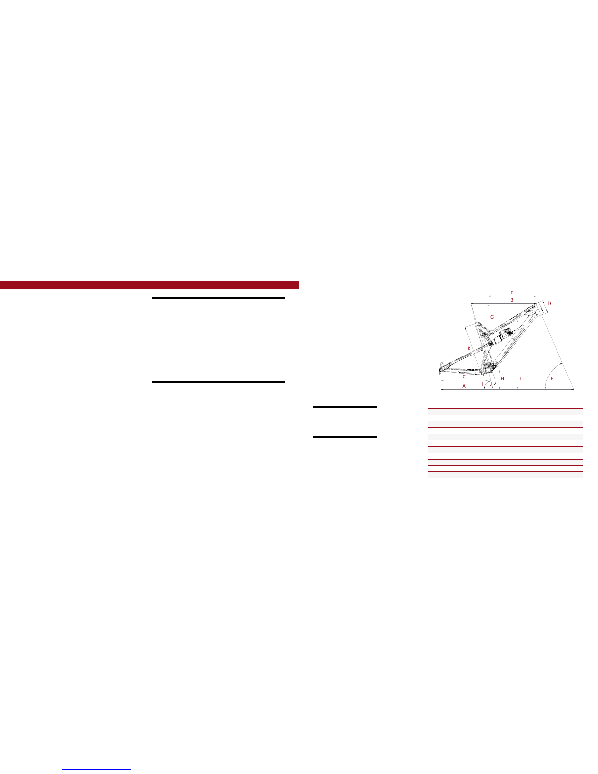
Geometry
A
B
C
F
E
D
G
H
L
K
I
J
GEOMETRY NOTEs
GEOMETRY TAKEN AT TOP OUT WITH 552MM
FORK LENGTH AND 42MM FORK OFFSET.
Component spec NOTE
the Tracer carbon is designed around
the use of a single chain ring. Use of a
double or triple ring set will not allow
proper clearance with the frame.
Frame Features //
•Travel: 6.5" (165mm)
•27.5” Wheel size
•Integrated BOOST 148 x 12 dropouts
•6.15 lbs / 2,790 grams = Standard frame w/ alloy link, no shock
•5.7 lbs / 2,568 grams = SL Super Light frame w/ carbon link, no shock
•INTERNAL CABLE ROUTING
•Internal Seat Tube Cable Routing for dropper posts
•Monocoque front triangle
•FLack GuaRD Downtube and Chainstay protection
•Tapered Head Tube
•Angular Contact/Collet Bearing System with replaceable Grease Zerks
Component Spec //
•Fork – 1.5” tapered steer, 165mm Travel, 552mm lower leg length, 42mm offset
•Shock – 216mm x 63.5mm (8.5” x 2.5”), 22mm x 6mm and 22mm x 8mm reducers
•Seat post – 31.6mm
•Headset – Cane Creek, 40, Alloy Cartridge (www.canecreek.com)
•Bottom bracket - PF92
•Rear Axle – BOOST 148 x 12 T/A
•Brake Mount – post mount - direct 180mm
•Crank set - BOOST 148 Compatible - single ring only
•Rear Wheel - BOOST 148 Compatible
SMALL MEDIUM LARGE XLARGE
AWheel Base: 1154 mm/ 45.4” 1181 mm/ 46.5” 1207 mm/ 47.5” 1235 mm/ 48.6”
BTop Tube Length: 571 mm/ 22.5” 597 mm/ 23.5” 622 mm/ 24.5” 649 mm/ 25.5”
CChain Stay Length: 432 mm/ 17” 432 mm/ 17” 432 mm/ 17” 432 mm/ 17”
DHead Tube Length: 102 mm/ 4” 115 mm/ 4.5” 119 mm/ 4.7” 130 mm/ 5.1”
EHead Tube Angle: 65.5˚ 65.5˚ 65.5˚ 65.5˚
F Reach: 414 mm/ 16.3” 436 mm/ 17.2” 460 mm/ 18.1” 483 mm/ 19”
G Stack: 589 mm/ 23.2” 600 mm / 23.6” 604 mm/ 23.8” 614 mm/ 24.2”
HBB Height: 343 mm/ 13.5” 343 mm/ 13.5” 343 mm/ 13.5” 343 mm/ 13.5”
ISeat Tube Angle (Effective): 75˚ 75˚ 75˚ 75˚
JSeat Tube Angle (Actual): 71˚ 71˚ 71˚ 71˚
KSeat Tube Length: 396 mm/ 15.6” 434 mm/ 17” 459 mm/ 18” 485 mm/ 19”
LStandover Height: 795 mm/ 31.3” 801 mm/ 31.6” 805 mm/ 31.7” 813 mm/ 32”
6// tracer carbon user manual INTENSE CYCLES // 7
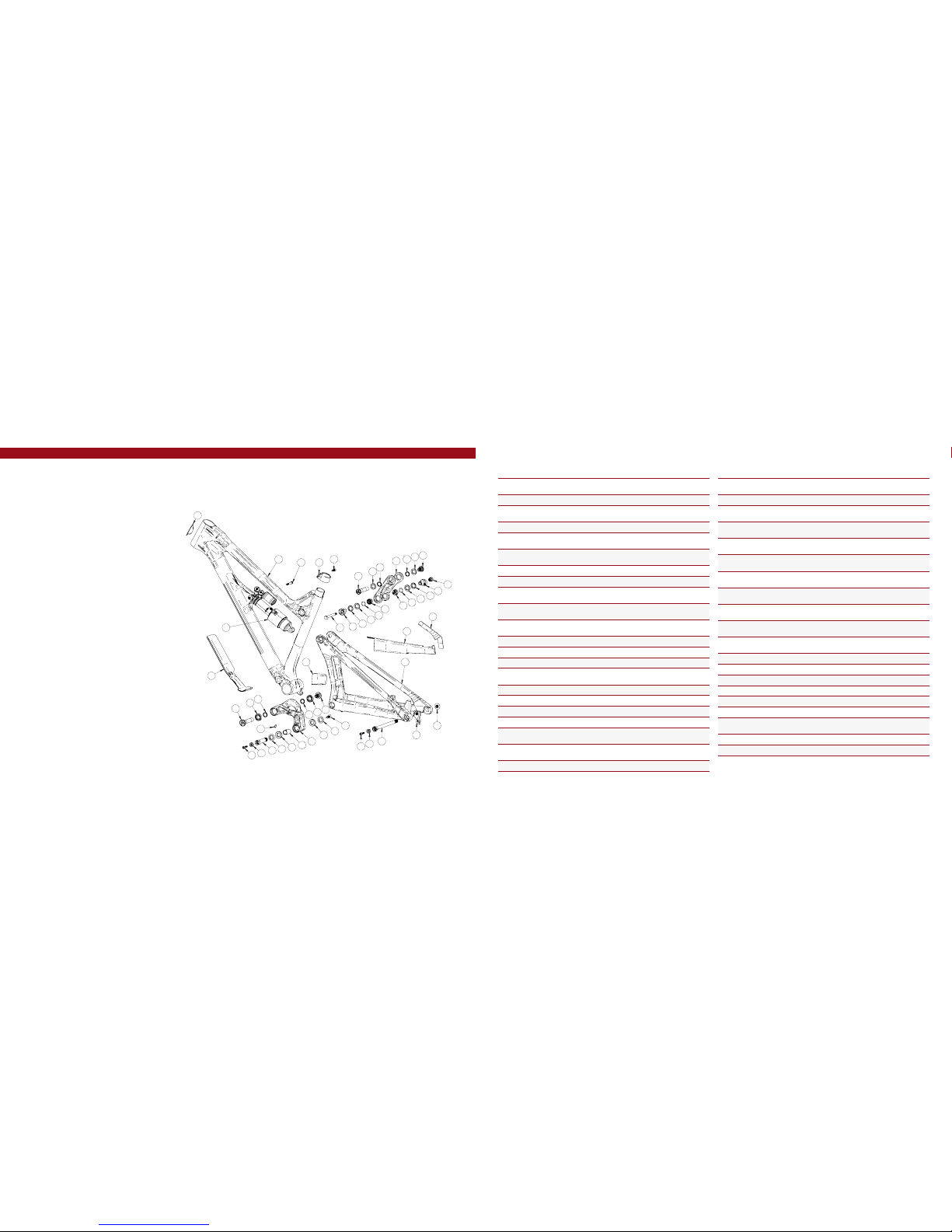
exploded view
and b.o.m.
36
38
22
29
5
29 6
39
33
10
1
8
3
7
25 16
4
28
4
21
28
27
37
9
34
24
29
3
29
31
13
19
7
17
14
20
12
22
15
30
7
7
30
11
26
23
12
18 16
25
2
32
ITEM
NO. ITEM PART
NUMBER DESCRIPTION QTY. TORQUE
SPEC.
1Rear Axle 130757 Axle 148 x 12 Boost 111 Nm /
100 in-lbs
2Bearing Spacer 130758 Lower Link Bearing Spacer 1N/A
3Bearing Cap
24mm OD 130765 Top Link Bearing Spacer
(Lower) 2N/A
4Bearing Cap 130778 Lower Link Bearing Cap 2N/A
5Axle Upper 130780 Top Link Pivot Axle
(U p p e r) 120 Nm /
175 in-lbs
6Bolt Shoulder 130785 Top Link Pivot Bolt 120 Nm /
175 in-lbs
7Spacer 130789 Bearing Spacer 4N/A
8Hanger 130790 Derailleur Hanger Forged 1N/A
9Bolt Main Pivot 130791 Lower Link Expander Bolt 17 Nm /
60 in-lbs
10 Hanger Bolt 130798 Derailleur Hanger Bolt 111 Nm /
100 in-lbs
11 Axle Lower 130800 Lower Link Axle 120 Nm /
175 in-lbs
12 Link Spacer 130801 Upper Link Spacer 2N/A
13 D-Lock Reducer 130803 Non-Drive Side Reducer 1N/A
14 D-Lock Reducer 130805 Drive Side Reducer 1N /A
15 Bolt Shoulder 130806 Lower Link Pivot Bolt 120 Nm /
175 in-lbs
16 Cone Adjuster 130807 Cone Adjuster Blk, 8.3 mm Height 2N/A
17 Top Link Standard 130811 Forged Top Link 1N /A
17 Top Link SL 130809 Carbon Top Link 1N /A
18 Lower Link 130812 Forged Lower Link 1N/A
19 Shock Bolt 130813 D-Lock Bolt 116 Nm /
140 in-lbs
20 Shock Bolt Nut 130814 D-Lock Nut 116 Nm /
140 in-lbs
21 Push Rivet 140038 Lower Link Push Rivet SR-0817BK 1N /A
ITEM
NO. ITEM PART
NUMBER DESCRIPTION QTY. TORQUE
SPEC.
22 O-Ring 140044 Upper LInk O-Ring
13.8 mm ID x 2.4 mm Width 2N /A
23 Seat Clamp 340342 Tracer Carbon Seat Clamp 1N /A
24 Zerk Fitting
M6 x 1.0 401011 M6 x 1.0 15 Nm /
40 in-lbs
25 SHCS M6 x 22 410009 Cone Adjuster Bolt,
Socket Head, M6 x 22 214 Nm /
125 in-lbs
25 SHCS M6 x 22 410032 Cone Adjuster Bolt,
Socket Head, M6 x 22 Titanium 214 Nm /
125 in-lbs
26 SHCS M6 x 18 410048 Seat Clamp Bolt,
Socket Head, M6 x 18 114 Nm /
125 in-lbs
27 SHCS M6 x 40 410053 Front Shock Bolt,
Socket Head, M6 x 40 17 Nm /
60 in-lbs
27 SHCS M6 x 40 410050 Front Shock Bolt,
Socket Head, M6 x 40 Titanium 17 Nm /
60 in-lbs
28 Bearing 7902 430007 15 x 28 x 7 2RS
MAX Angular Contact Bearing 2N /A
29 Bearing 6802 430008 15 x 24 x 5 2RS
MAX Radial Bearing 4N/A
30 Bearing 6902 430009 15 x 28 x 7 2RS
MAX Radial Bearing 2N/A
31 Guard Flack DT 500269 Flack Guard DT 1N/A
32 Guard Flack CS 500270 Flack Guard Chainstay 1N /A
33 Guard Flack Ststy 500271 Flack Guard Seat Stay 1N/A
34 Protector Chainstay 500272 Protector Chainstay 1N /A
35 Decal 500300 Decal California Bear 1N/A
36 Head Badge 500335 Head Badge Flame Logo 1N /A
37 Rear Shock 8.5in x 2.5in
(215.9mm x 63.5mm) 1N/A
38 Front Triangle Carbon - 4 Sizes 1N/A
39 Rear Triangle Carbon - 1 Size 1N/A
(ST)
(ST)
(ST)
(SL)
(SL)
(SL)
8// tracer carbon user manual INTENSE CYCLES // 9
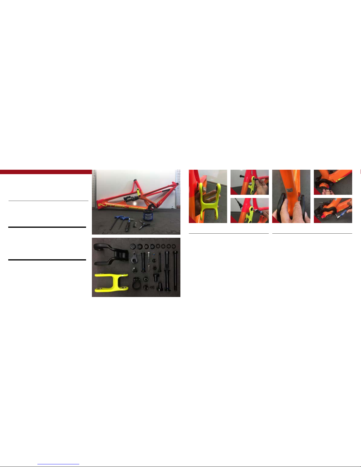
Assembly
Tools needed
•High Grade, waterproof grease (Maxima Waterproof Grease recommended)
•Blue Loctite®#243
•5mm HEX wrench x2
•6mm hex wrench
•8mm HEX wrench
•torque wrench
Recommendation
•APPLY A THIN COAT OF GREASE TO ALL PIVOT AXLES AND REAR AXLE to REDUCE THE
CHANCE OF CORROSION DUE TO MOISURE AND PREVENT POSSIBLE CREAKS.
•AFTER THE FIRST FEW RIDES THE COMPONENTS Are BROKEN IN AND SETTLED INTO
PLACE, GO THROUGH AND RE TORQUE ALL PIVOT AXLES. AFTER THIS FIRST ADJUSTMENT,
YOU WILL BE READY TO RIP FOR THE LONG HAUL.
•USE GREASE IN ANY ALLOY TO CARBON INTERFACE, INCLUDING BB AND HEADSET.
PR E FA C E //
Service and maintenance on an Intense bicycle requires special tools, abilities and
knowledge of working on bicycles. It is always recommended to use an authorized
Intense dealer for service and maintenance. Always wear eye protection. It is critical
to use the proper tools, loctite, grease and torque specs during assembly. Failure to
follow these instructions may result in serious bodily injury or death.
2 5
3 6
CONNECTING TOP LINK TO FRONT TRIANGLE //
AHolding top link (#130809) as oriented
in the above picture, with your fingertips,
hold upper link pivot bolt spacers
(#130789) against the inside of the
bearing races (IMAGE #1).
BMatch upper link to pivot point on the
top tube making sure the spacers do
not fall out.
CUsing upper pivot axle (#130780),
insert through non-drive side of top link
bearing and push through to drive side
bearing (IMAGE #2).
DThread shoulder bolt (#130785) using
5mm HEX wrench. Holding 5MM wrench
on non-drive side and 5MM torque wrench
on shoulder bolt, torque the assembly to
20 NM / 175 in/lbs (IMAGE #3).
CONNECTING BOX LINK TO FRONT TRIANGLE //
AHolding the lower link (#130812)
behind the seat tube, use your fingertips
to hold lower link spacers (#130789)
against the inside of the bearing races
(IMA G E #4).
BSlide over and match lower link to
pivot point on down tube making sure
the spacers do not fall out (IMAGE #4).
CUsing lower link pivot axle (#130800),
insert through non-drive side of lower
link bearing and push through to drive
side bearing (IMAGE #5).
DThread shoulder bolt (#130806) using
5mm HEX wrench. Holding 5MM wrench
on non-drive side and 5MM torque wrench
on shoulder bolt, torque the assembly to
20 NM / 175 in/lbs (IMAGE #6).
1 4

10 // tracer carbon user manual INTENSE CYCLES // 1 1
INSTALLING REAR SHOCK //
AUsing rear shock with the reservoir
facing up, match the body and reservoir
with the front triangle shock tabs. Insert
the M6 x 40MM shock bolt through the
assembly and torque down to 14 NM /
125 in/lbs (IMAGE #18).
BMatch the other end of the shock with
the D-Lock reducers and the link spacers
on the top link. Insert the keyed shock
shoulder bolt (#130813) making sure it
is keyed properly and is fully flushed with
the D-Lock reducer on non-drive side
(IMAGE #19).
CThread on shock nut (#130814) with
5MM allen key and torque down to 16 NM
/ 140 in/lbs (IMAGES #20, 21).
8
7911
10 12 13
201814 16
211915 17
CONNECTING REAR TRIANGLE TO BOX LINK //
APut a small dab of grease on the
outside bearing race as well as on
the contacting surface of the bearing
cap (#130778). This will help hold
the bearing caps in place during the
installation (IMAGE #7).
BSlide rear triangle over the lower link
and line up the pivot point over the
bearing caps (IMAGE #8).
CInsert greased main pivot bolt
(#130791) into non-drive side of lower
link. Insert 8MM torque wrench and
torque main pivot bolt down to 7 NM /
60 in/lbs (IMAGES #9, 10).
DGrease and insert cone adjuster
(#130807) into main pivot bolt with M6
x 22MM bolt (#410009) (IMAGE#11).
Torque down to 14 NM / 125 in/lbs
(IMAGE #12).
EInsert push rivet (#140038) on the
drive side in the pivot axle (IMAGE # 13).
CONNECTING REAR TRIANGLE TO TOP LINK //
APut a small dab of grease on the outside
bearing race as well as on the contacting
surface of the bearing cap (#130765).
This will help hold the bearing caps in
place during the installation (IMAGE #14).
BSwing the rear triangle up aligning the
pivot point with upper link bearing cap
(IMAGE #15).
CInsert the non-drive D-Lock reducer
(#130803) and the drive side D-Lock
reducer (#130805), joining the top swing
link with the rear triangle (IMAGE #16).
DTake the upper link spacer (#130801)
and slide it over the back side of the
D-Lock reducer on both drive and non-
drive sides. It will be a snug fit as there
is a small o-ring fitted to the inside
diameter of the tracer spacer. This
spacer will directly interface with the
shock hardware (IMAGE #17).

torque
Achieving proper torque is vital to
ensuring the safe performance and
function of the tracer carbon frame.
Failure to do so could result in sub-
optimal performance of your frame
as well as premature wear and tear
of individual parts.
additional reference
In addition to this chart, all torque
values are laser etched onto
corresponding hardware for your
reference.
12 // tracer carbon user manual INTENSE CYCLES // 1 3
torque chart
20 Nm / 175 in/lbs
20 Nm / 175 in/lbs
16 Nm / 140 in/lbs
14 Nm / 125 in/lbs
M8 HEX 7 Nm / 60 in/lbs
M6 HEX 14 Nm / 125 in/lbs
Derailleur Cap: 11 Nm / 100 in/lbs
Axle (drive side): 11 Nm / 100 in/lbs
Axle (non-drive side): 14 Nm / 125 in/lbs
REAR AXLE //
AInsert 148 x 12MM rear axle (#130757)
into axle opening on non-drive side
(IMA G E #24).
BFrom drive side, insert 5MM allen key
through the derailleur cap to reach the
5MM HEX interface on the axle. Turn
wrench in a counter clockwise direction
to tighten and clockwise to loosen. Torque
to 11 NM / 100 in/lbs (IMAGE #25).
CBack on the non-drive side, use the
5MM allen wrench to torque the cone
adjuster (#130807) with the M6 x 22MM
(#410032) down to 14 NM / 125 in/lbs
(IMAGE #26).
24
2625
2322
INSTALLING DERAILLEUR HANGER //
AApply a thin layer of grease to the
derailleur hanger (#130790) shank and
install into the keyed insert on the drive
side of the rear triangle (IMAGE #22).
BInstall derailleur cap (#130798) using
a 6MM allen key and torque to 11 NM /
100 in/lbs (IMAGE #23).
seatpost
make sure to insert seat post at least 4” into the main frame. Anything less than
this amount could cause damage to the frame or even failure.
14 // tracer carbon user manual INTENSE CYCLES // 1 5
set up
4”
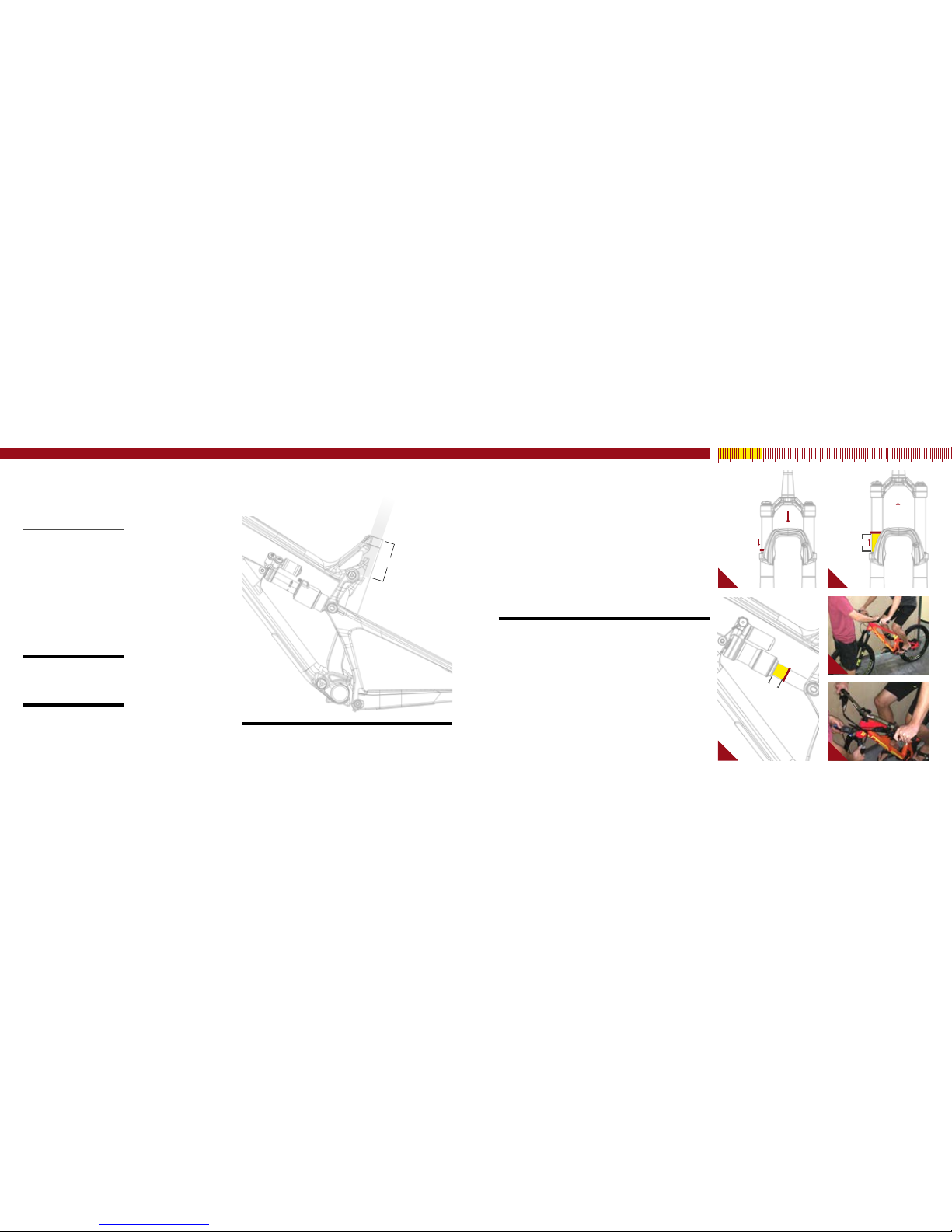
setting the sag
1. Remove fork and shock air caps and be sure you have a shock
pump and a small ruler or measuring device handy.
2. Go ahead and hop on the bike. Be sure to place all your weight on the
seat with the dropper in the up position and both hands on the grips.
3. Give the bike 5-6 moderate bounces and sit back down on the saddle.
4. Now have your friend slide both the rear shock and the front fork
o-rings down against the seal lip of the damper bodys (IMAGE #1).
5. Step off the bike nice and easy. Be sure to not compress the suspension
after the o-rings have been set.
Pro Tip
Here is where having a friend helps. Have them straddle the front wheel and pull
the handle bars in a upward direction as to not allow the suspension to compress
as you get off (image #4).
6. Using your measuring device, measure the gap between the suspension
seal lip and the o-ring. Using the chart on the following page will tell you
if you need more air pressure or less air pressure (IMAGES #2, #3).
7. Adjust air pressure with your shock pump accordingly (IMAGE #5).
8. Re-visit steps 2-6 until your desired sag measurement have been reached.
9. Install valve caps.
10. Go ride your bike!
15% - 25%
While suspension
is compressed on
fork or rear shock,
slide o-ring down
against the seal lip
of damper body.
Release compression.
Measure gap from
o-ring to seal lip.
19mm
seatpost
PR E FA C E //
We are almost ready to rip. Just a few
more checkpoints and adjustments
to ensure the performance and ride
characteristics of the Tracer Carbon is
optimised for you.
Tools needed
•shock pump
•small ruler or measuring device
recommendation
When setting up the suspension sag,
ask a fellow ripper to help. but if
alone, using a wall to lean your
shoulder against will do just fine.
4
21
3 5
cm 1 2 3 4 5 6 7 8 9 10

16 // tracer carbon user manual INTENSE CYCLES // 1 7
shock setup
FOX FLOAT x2 performance elite / x2
216 x 63.5mm
set up and tune
proper set up and tuning can vary
from shock to shock. Please
consult the Fox manual included
with your bike for complete
information about set up, tuning
and general maintenance or visit
www.foxracingshox.com
Travel 165mm
Shock Stoke 63mm
Shock Sag 30% when sitting on the bike
Fork Sag 15-25% when sitting on the bike
SHOCK: FOX Float X2 Performance Elite
SHOCK: FOX Factory Float X2
RIDER WEIGHT(LBS/KGS) SPRING (PSI)
100 lbs/ 45 kgs 120 LSC 20
110 lbs/ 50 kgs 130 HSC 18
120 lbs/ 54 kgs 140 LSR 17
130 lbs/ 59 kgs 150 HSR 15
140 lbs/ 63.5 kgs 160 LSC 18
150 LBS / 68 KGS 170 HSC 16
160 LBS / 73 KGS 180 LSR 14
170 LBS / 77 KGS 190 HSR 12
180 LBS / 82 KGS 200
190 LBS / 86 KGS 210 LSC 17
200 LBS / 91 KGS 220 HSC 14
210 LBS / 95 KGS 230 LSR 13
220 LBS / 100 KGS 240 HSR 10
230 LBS / 104 KGS 250
240 LBS / 109 KGS n/a
n/a
250 LBS / 113 KGS n/a
260 LBS / 118 KGS n/a
270 LBS / 122 KGS n/a
280 LBS / 127 KGS n/a
290 LBS / 131.5 KGS n/a
300 LBS / 136 KGS n/a
set up and tune
proper set up and tuning can
vary from shock to shock. Please
consult the rockshox manual
included with your bike for complete
information about set up, tuning
and general maintenance or visit
www.sram.com/rockshox/products
Travel 165mm
Shock Stoke 63 mm
Shock Sag 30% when sitting on the bike
Fork Sag 15-25% when sitting on the bike
SHOCK: Rock Shox Monarch Plus R
SHOCK: Rock Shox Monarch Plus RT3
RIDER WEIGHT(LBS/KGS) SPRING (PSI) REBOUND (clicks out)
100 lbs/ 45 kgs 100
7-6
110 lbs/ 50 kgs 110
120 lbs/ 54 kgs 120
130 lbs/ 59 kgs 130
140 lbs/ 63.5 kgs 140
150 LBS / 68 KGS 150
6-5
160 LBS / 73 KGS 160
170 LBS / 77 KGS 170
180 LBS / 82 KGS 180
190 LBS / 86 KGS 190
200 LBS / 91 KGS 200
210 LBS / 95 KGS 210
220 LBS / 100 KGS 220
230 LBS / 104 KGS 230
4-3
240 LBS / 109 KGS 240
250 LBS / 113 KGS 250
260 LBS / 118 KGS 260
270 LBS / 122 KGS 270
280 LBS / 127 KGS 280
290 LBS / 131.5 KGS 290
300 LBS / 136 KGS 300
shock setup
rock shox monarch Plus r / rt3
216 x 63.5mm

18 // tracer carbon user manual INTENSE CYCLES // 1 9
maintenance maintenance Schedule*
Action Every Ride 500 Miles or
1 Month
2000 Miles or 6
Months
4000 Miles or
1 Year
Tires Check air pressure, inspect tread and sidewalls for tears and punctures X
Chain Brush off and lubricate X
Brakes Squeeze brakes and confirm function X
General Clean complete bike of mud and debris X
Headset Check adjustment X
Box Link Add grease thru zerk fittings X
Frame Pivots Check torques X
Spokes Inspect for damage, check tension X
Shock and Fork Check air pressure, inspect for leaks X
Deraileur Cables Inspect and lube X
Seatpost Clean and regrease interface with frame X
Frame Pivots Remove pivot bolts, check bearings for pitting and wear X
Headset Disassemble stem, headset and fork. Check bearings for pitting and wear X
Hubs Pull wheels off, check hub bearings for pitting and wear X
Bottom Bracket Remove crank arms and check BB bearings for pitting and wear X
Brakes Replace brake pads X
Chain Inspect for damage and check for stretching X
General Complete Tune-Up X
Shock and Fork Overhaul See MFG Recommendations
GENERAL SERVICE AND CARE //
You have purchased a high performance bicycle which requires a certain level of service
and maintenance to sustain the level of performance your frame was designed around.
Proper care will also ensure the bike is safe to ride at all levels. It is important to read
and understand the carbon care information as well as follow the maintenance schedule
and inspect your bicycle before each ride. These will not only help to limit or avoid costly
repairs but will also help to avoid injury due to service neglect and component failure.
carbon care
Intense Cycles employs advanced composite techniques and materials in
our frames which do require a certain level of care and maintenance to
ensure a safe experience at the high level of performance each frame is
designed around. Not following these guidelines will decrease the level
of performance and possibly cause injury or death.
• Use a soft cloth with warm soapy water to clean the carbon surfaces. Do
not use abrasive cloths or cleaners.
• Be sure all frame surfaces in contact with cables are protected. Cable
housing rubbing on carbon can wear over time.
• Be sure brake levers, handle bar ends and the fork crown do not contact
the frame at full rotation.
• Never clamp any part of a carbon frame in a bike stand or car rack.
• Always inspect your frame if you experience any chain suck. Intense
frames come equipped with steel chain suck plates but damage can still
be done in the event of chain suck.
• Always inspect your frame in full after a crash to be sure there is no
damage. Look for cracks, dents or loose fibers. If you discover damage
in any degree it’s best to have your frame inspected by a qualified
Intense Cycles dealer. Any direct impact to the frame can cause serious
structural damage.
• Use high grade waterproof grease on seat post, BB and head set bearing
contact areas with the carbon.
• Never ream or face a carbon frame.
• Be sure to follow all recommended torque settings.
*THE ABOVE MAINTENANCE SCHEDULE IS ONLY A GUIDELINE. refer to COMPONENT MANUFACTURER FOR SPECIFIC INSTRUCTION ON MAINTAINING THEIR PARTS.

phone: (951)-296-9596
Customer Service: cs@intensecycles.com
General Info: info@intensecycles.com
Media, Marketing, Sponsorship: marketing@intensecycles.com
Intense Cycles USA 42380 rio nedo Temecula, Ca. 92590
www.INTENSeCYCLES.com
330021
Table of contents
Other INTENSEcycles Bicycle manuals

INTENSEcycles
INTENSEcycles PRIMER 29 User manual

INTENSEcycles
INTENSEcycles 951 EVO User manual

INTENSEcycles
INTENSEcycles Spider 275 User manual

INTENSEcycles
INTENSEcycles ACV User manual

INTENSEcycles
INTENSEcycles M16 Carbon User manual

INTENSEcycles
INTENSEcycles M9 PRO User manual

INTENSEcycles
INTENSEcycles 951 Series User manual

INTENSEcycles
INTENSEcycles Recluse User manual

INTENSEcycles
INTENSEcycles TAZER User manual

INTENSEcycles
INTENSEcycles carbine 275 User manual


