Tomtar MR-S User manual

EN
TOMTAR MR-S & TOMTAR MR-LG
Standard & lightweight wheelchair
User manual Version 3.1

Thank you for choosing the TOMTAR MR-S / MR-LG manual
wheelchair from DIETZ.
Read these operating instructions carefully be-
fore starting to use your new TOMTAR MR-S /
MR-LG. They contain important safety instruc-
tions and valuable tips on correctly using the
wheelchair.
They also contain information concerning opera-
tional safety, road safety and the best possible
value retention of your wheelchair.
If you have any questions or require additional
information, please contact the specialist retailer
which supplied the wheelchair to you.
You can always find the latest version of the user
manual and information on your product on our
homepage. For information or queries concern-
ing product safety and on recalls, please contact
DIETZ in writing or by telephone. You will find our
contact information on the back of these operat-
ing instructions.
For reasons of better readability, the simultaneous
use of the language forms masculine, feminine
and diverse (m/f/d) is dispensed with in the follow-
ing and the generic masculine is used.All personal
designations apply equally to all genders.
3
EN
FOREWORD
Record of product identification data
We recommend that you write down your product identification data below (found on product
label), so that you have these on hand should you require any further information about your
product. (see chapter product labelling)*
Type / model:
Item No. / REF:
Serial number:
Date of manufacture:
Other information/notes:
* The identification data on your product label may differ on custom-made devices.
HINWEIS
A large-print version of the opera-
ting instructions is available for
visually impaired persons at
www.dietz-group.de in PDF
format.

4 5
TOMTAR MR-S/MR-LG user manual / version 3.1 EN
EN
TABLE OF CONTENTS
5 Individual adjustments
Important information on adjustments. . . . . .26
Tools . . . . . . . . . . . . . . . . . . . . . . . . . . . . . .26
5.1 Lower leg length. . . . . . . . . . . . . . . . . .26
5.2 Adjustable backrest
(only TOMTAR MR-LG) . . . . . . . . . . . 27
5.3 Armrests. . . . . . . . . . . . . . . . . . . . . . . .27
5.4 Adjusting the push handle
(only TOMTAR MR-LG) . . . . . . . . . . . . .28
5.5 Seat depth . . . . . . . . . . . . . . . . . . . . . .28
5.6 Seat height adjustment . . . . . . . . . . . . .29
5.7 Parking brakes . . . . . . . . . . . . . . . . . . .30
5.8 Drum brake (optional) . . . . . . . . . . . . . .30
5.9 Wheelbase extension (optional). . . . . . .31
5.10 Anti-tipping supports (optional). . . . . . .32
5.11 Angle-adjustable foot plates . . . . . . . . .32
5.12 Safety belt (optional). . . . . . . . . . . . . . .33
5.13 Height-adjustable side panel
(optional) . . . . . . . . . . . . . . . . . . . . . . .33
5.14 Amputee support (optional) . . . . . . . . .34
5.15 Brake lever extension (optional) . . . . . .34
5.16 Therapy tray (optional) . . . . . . . . . . . . .35
5.17 Elevating leg rest (optional). . . . . . . . . .35
5.18 Accessories and add-ons from external
suppliers. . . . . . . . . . . . . . . . . . . . . . . .37
06 Technical data
Wheelchair dimensions . . . . . . . . . . . . . . . . .38
Technical specifications . . . . . . . . . . . . . . . . .39
Materials . . . . . . . . . . . . . . . . . . . . . . . . . . .40
07 Safety instructions
Safety information & driving restrictions. . . . .42
08 Instructions for general use
Servicing/maintenance. . . . . . . . . . . . . . . . . .44
Maintenance schedule . . . . . . . . . . . . . . . . .45
Troubleshooting . . . . . . . . . . . . . . . . . . . . . .47
Cleaning . . . . . . . . . . . . . . . . . . . . . . . . . . . .48
Disinfection. . . . . . . . . . . . . . . . . . . . . . . . . .48
Forwarding / reusING . . . . . . . . . . . . . . . . . .49
Storage. . . . . . . . . . . . . . . . . . . . . . . . . . . . .49
Disposal . . . . . . . . . . . . . . . . . . . . . . . . . . . .49
Product labelling . . . . . . . . . . . . . . . . . . . . . .50
09 Manufacturer‘s declarations
Warranty . . . . . . . . . . . . . . . . . . . . . . . . . . .51
Lifetime. . . . . . . . . . . . . . . . . . . . . . . . . . . . .51
Liability. . . . . . . . . . . . . . . . . . . . . . . . . . . . .51
TABLE OF CONTENTS
1 Important information
Intended purpose . . . . . . . . . . . . . . . . . . . . . .6
Indications . . . . . . . . . . . . . . . . . . . . . . . . . . .6
Contraindications . . . . . . . . . . . . . . . . . . . . . .7
Symbols . . . . . . . . . . . . . . . . . . . . . . . . . . . . .7
2 Product description
Scope of delivery . . . . . . . . . . . . . . . . . . . . . . .8
Accessories (optional) . . . . . . . . . . . . . . . . . . .8
Structure of the TOMTAR MR-S/MR-LG . . . . . .9
3 Setting up the wheelchair
Preparing the wheelchair for use . . . . . . . . . .10
3.1 Folding/unfolding the wheelchair. . . . . .10
3.2 Backrest upholstery. . . . . . . . . . . . . . . .11
3.3 Attaching the leg rests . . . . . . . . . . . . .11
4 Using the wheelchair
Using the wheelchair. . . . . . . . . . . . . . . . . . .12
4.1 Getting in and out of your wheelchair . . .12
4.2 Swivelling the side panels/armrests . . . .14
4.3 Removing the side panels/
armrests . . . . . . . . . . . . . . . . . . . . . . . .14
4.4 Folding up the foot plates . . . . . . . . . . .15
4.5 Swivelling and detaching the
leg rests . . . . . . . . . . . . . . . . . . . . . . . .15
4.6 Propelling and slowing down the . . . . . . .
wheelchair with the push rims. . . . . . . .16
4.7 Driving on gradients and uneven ground . .
17
4.8 Loading the wheelchair. . . . . . . . . . . . .17
4.9 Parking brakes . . . . . . . . . . . . . . . . . . .18
4.10 Drum brakes for an attendant
(optional) . . . . . . . . . . . . . . . . . . . . . . .19
4.11 Removing and attaching rear
wheels . . . . . . . . . . . . . . . . . . . . . . . . .20
4.12 Transport . . . . . . . . . . . . . . . . . . . . . . .21
Transport of the wheelchair without user . . . .21
Wheelchair as a car seat . . . . . . . . . . . . . . . .22
Attaching the wheelchair
restraint systems . . . . . . . . . . . . . . . . . . . . .23
Wheelchair user restraint system . . . . . . . . . .24
6 7
TOMTAR MR-S/MR-LG user manual / version 3.1 EN
EN
1IMPORTANT INFORMATION
CONTRAINDICATIONS
Use of the wheelchair is unsuitable in the case of
P False sensations
P Severe disequilibrium
P Loss of limbs on both arms
P Joint contracture/joint damage on both arms
P Inability to sit
P Impaired or inadequate vision.
SYMBOLS
These symbols indicate passages of text that are helpful for using and oper-
ating the product in every day life.
WARNING
It is mandatory to observe and comply with warnings.
They inform you of circumstances that could result in injury and/or dama-
ge to the wheelchair or surroundings if the warnings are not observed.
NOTE
Tips and advice to simplify using the functions.
1 IMPORTANT INFORMATION
INTENDED PURPOSE
The wheelchair TOMTAR MR-S / MR-LG is only intended to be used to carry
persons with a maximum bodyweight of 130 kg. It can be used indoors and
outdoors.
Persons who use the wheelchair independently must be physically and men-
tally capable of moving and braking the wheelchair. The user must have
sufficiently good eyesight to use the wheelchair in public spaces and to use
public highways.
If the wheelchair is moved by an accompanying person, the accompanying
person must be physically capable of pushing and braking the occupied
wheelchair.
The wheelchair is not suitable for children. The wheelchair shall not be used
for the transport of more than one person or of cargo.
The intended purpose may differ for products which were manufactured as
custom-made device and which have been labelled as such. In this case,
please refer to the documentation supplied with the product.
INDICATIONS
This wheelchair provides assistance for persons who are unable to walk or
who have a severe walking impediment due to
P Paralysis
P Loss of limbs
P Limb defect/deformation
P Joint contracture/joint damage (not on both arms)
P Other diseases.
8 9
TOMTAR MR-S/MR-LG user manual / version 3.1 EN
EN
2 PRODUCT DESCRIPTION
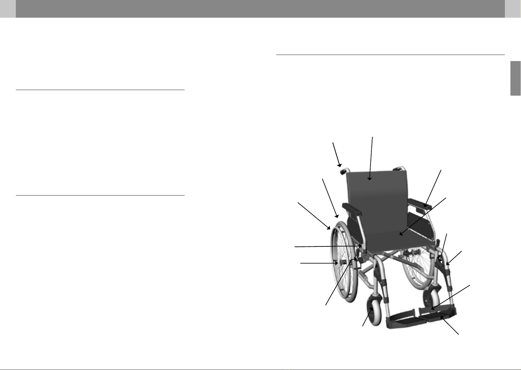
STRUCTURE OF THE TOMTAR MR-S/MR-LG
Basic components
The overview represents all models and shows the most important components of the
standard folding wheelchair. All illustrations show the standard TOMTAR MR-S wheelchair
unless stated otherwise.
Foot plate
Armrest locking lever
Leg rest locking lever
Side panel
Armrest
Backrest
Push handle
Push rims Seat
Heel strap
Swivel wheel
Quick-release axle
Parking brake
Rear wheel
Leg rest
fig. 1
2 PRODUCT DESCRIPTION
The TOMTAR MR-S / MR-LG is delivered completely assembled and pack-
aged in a box. If possible, please keep the packaging for possible later stor-
age of the wheelchair.
SCOPE OF DELIVERY
On receipt of the wheelchair, please immediately check to make sure
that the contents are complete and undamaged. The contents consist of:
P 1 set of cardboard box and packaging
P 1 pre-assembled wheelchair
P 1 pair of leg rests
P Operating instructions
P Multipurpose wrench (8, 10, 13, 16, 19 mm)
P Accessories (if selected)
ACCESSORIES (OPTIONAL)
Wheelchair accessories available from the manufacturer:
P Amputee support(s)
P Anti-tipping supports
P Safety belt
P Brake lever extension
P Wheelbase extension
P Height-adjustable side panel
P Therapy tray
P Angle-adjustable leg rests
10 11
TOMTAR MR-S/MR-LG user manual / version 3.1 EN
EN
1
2
3 SETTING UP THE WHEELCHAIR
3. Push back the backrest upholstery when
folding the wheelchair.
3.2 Backrest upholstery
The flap (1, fig. 3) of the backrest upholstery can
be fixed to the bottom of the seat pad with Vel-
cro to close the gap between backrest and seat.
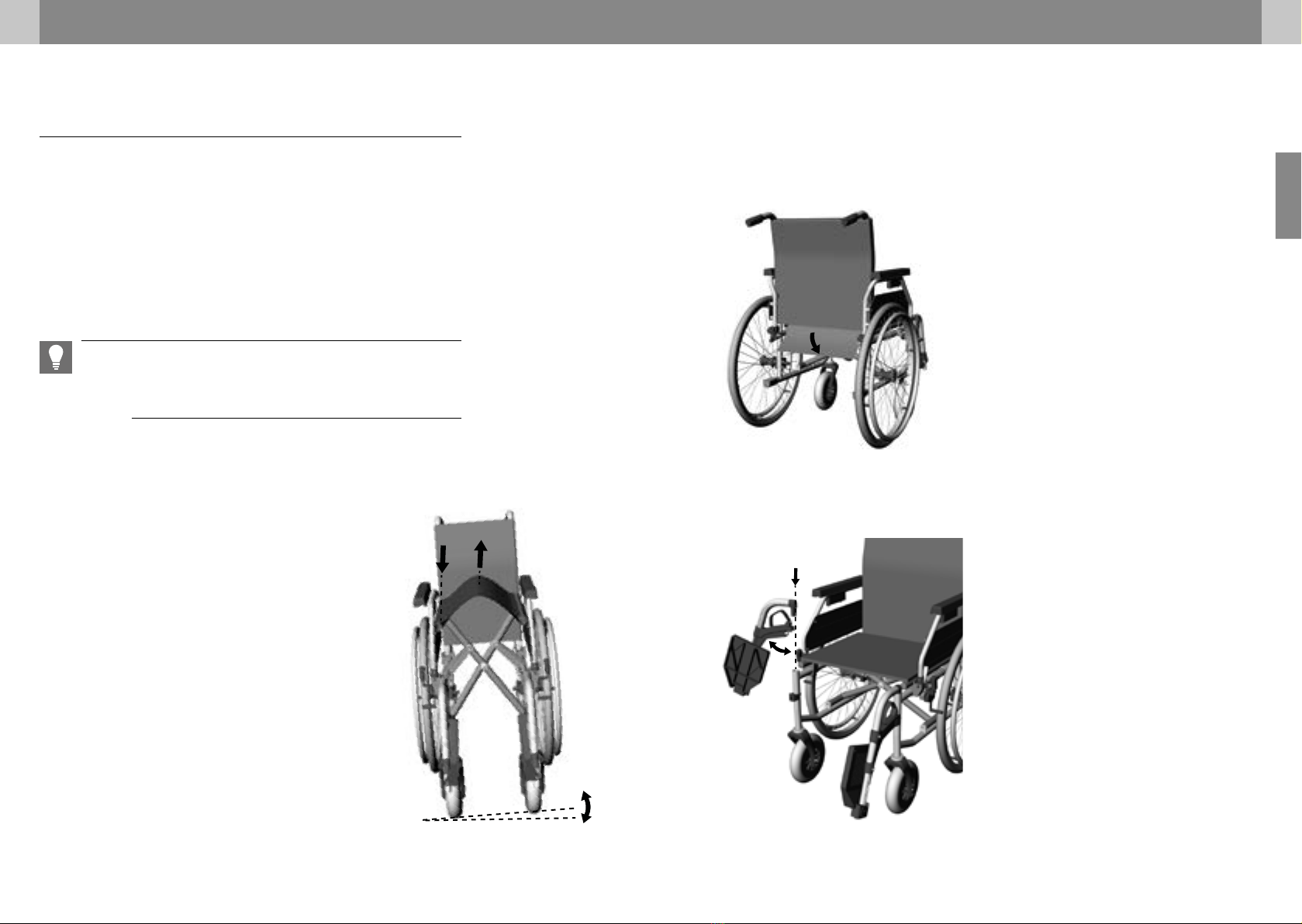
3.3 Attaching the leg rests
1. Insert the leg rest into the guide on the
wheelchair from above (1, fig. 4). When doing
so, the leg rest must be angled outwards. The
foot plate must be folded up.
2. Swivel the leg rest forwards (2, fig. 4). You
must hear and feel the leg rest engage.
3. Check that the leg rest is securely locked in
place.
4. The footplates are folded down after the leg
rests have been attached.
1
fig. 3
fig. 4
PREPARING THE WHEELCHAIR FOR USE
The following chapter contains information on how to unfold the wheelchair
and prepare it for use. Before using the wheelchair for the first time, you
need only to unfold the wheelchair, attach the leg rests and fix the Velcro
backrest upholstery flap in place.
The chapter ”05 Individual adjustments” contains explanations of all
the more complicated adjustment options, such as the seat height, angles
etc., that can be used for optimum adjustment.
3 SETTING UP THE WHEELCHAIR
3.1 Folding/unfolding the wheelchair
Unfolding the wheelchair
1. Tip the wheelchair slightly to one side (1, fig. 2).
2. On the opposite side, press the seat tube
downwards as far as it will go (2, fig. 2).
3. Tip the wheelchair back and set it down.
4. Check whether the wheelchair has unfolded
completely. To do so, press on the tubes on
both sides of the seat
Folding the wheelchair
1. Fold up the foot plates or remove the leg
rests. (Chapter 4.4 & 4.5)
2. Take hold of the front and back edges of the
seat cover and pull the seat cover upwards in
the middle (3, fig. 2). The wheelchair will then
fold automatically.
23
1
NOTE
The initial set-up should be carried out by trained personnel of the medical
supplies dealer.
fig. 2

12 13
TOMTAR MR-S/MR-LG user manual / version 3.1 EN
EN
4 USING THE WHEELCHAIR
Getting into your wheelchair
Take off the leg rests (see chapter 4.5).
If possible, place the wheelchair’s rear wheels against a solid
wall.
Apply the parking brakes to lock the wheelchair in place.
Stand as close as possible to the wheelchair. Turn around, then
carefully move backwards until your legs touch the edge of the
seat.
Now grab the armrest with your hands.
You can now sit down slowly and safely.
Swivel both the leg rests back to the front in the direction of
travel. Listen and feel for the click to ensure that the leg rests are
correctly engaged.
Finally, fold both the foot plates downwards using your feet and place
your feet on the foot plates (see chapter 3.3).
Getting out of your wheelchair
Carry the procedure out in the opposite sequence.
WARNING
Do not stand on the foot plates or footboard while getting up or sitting
down. They are not intended to bear the full weight of one person.
NOTE
To transfer sidewards, the side panel must be swivelled up (see chapter
4.2).
4 USING THE WHEELCHAIR
USING THE WHEELCHAIR
4.1 Getting in and out of your wheelchair
Different handicaps allow more or less manoeu-
vrability.
To get in and out of your wheelchair easily and
safely, the following tips can be helpful.
NOTE
Place the wheelchair backwards against a stab-
le wall (fig. 5). This ensures that the wheelchair
will not roll away on smooth surfaces.
fig. 5

14 15
TOMTAR MR-S/MR-LG user manual / version 3.1 EN
EN
4
5
2
1
3
4 USING THE WHEELCHAIR
4.4 Folding up the foot plates
1. Take hold of the foot plate by the front edge.
2. Swivel the foot plate upwards. (fig. 8)
WARNING
The user must not put their weight on the foot
plates when getting in and out of the wheel-
chair.
4.5 Swivelling and detaching the
leg rests
The leg rests can be swivelled to the side and
detached to make it easier to transfer onto or off
the wheelchair. This also allows you to move the
wheelchair closer to a bed or bathtub.
1. Fold the foot plate upwards (see chapter 4.4).
2. Pull the locking grip upwards (2, fig. 9)
3. Swivel the leg rest to the side (3, fig. 9).
4. If you wish to remove the leg rest: Take hold
of the leg rest on the horizontal part of the
tube and pull the leg rest upwards out of the
guide (4, fig. 9)
WARNING
When leg rests are swivelled outwards, they are
automatically unlocked and can easily become
detached from their mounts. Please be aware of
this, e.g. during transport!
fig. 8
fig. 9
4.2 Swivelling the side panels/armrests
The side panels can be swivelled upwards/back
along with the armrests to enable users to trans-
fer onto or off the wheelchair from the side.
1. Press the side panel locking lever forwards
(1, fig. 6).
2. Take hold of the side panel by the tube in
front of the armrest and swivel the side panel
upwards/back (2, fig. 6)
When swivelling the side panel downwards: In-
sert the tube of the side panel into the fixture
and ensure that it engages correctly (3, fig. 6)
4.3 Removing the side panels/
armrests
1. Swivel the side panel upwards/back (4.2).
2. Pull the rear pin on the clamping device
downwards (4, fig. 7).
3. Grip the side part by the armrest and pull it
back out of the holder (5, fig 7).
To reattach the side panel, perform these
actions in reverse order.
NOTE
The rear mount must be guided into the fixture
when inserting the side panel /armrest. Ensure
that the locking pin audibly engages.
4 USING THE WHEELCHAIR
fig. 6
fig. 7
2
1
3
4

16 17
TOMTAR MR-S/MR-LG user manual / version 3.1 EN
EN
4.7 Driving on gradients and uneven
ground
Potholes and uneven ground can cause the
wheelchair to tip over when driving over ramps,
slopes, gradients and kerbs.
Lean your body forwards when driving upwards
over a step or slope. (1 & 2, fig. 11)
Lean your upper body further backwards when
driving down slopes and steps. (3 & 4, fig. 11)
WARNING
Always drive up or down slopes/gradients in a
straight line and at a reduced speed. Do not dri-
ve over slopes or gradients obliquely as this in-
creases the risk of tipping over.
WARNUNG
If you brake the wheelchair for a long time
using the handrims, e.g. when driving downhill,
a lot of frictional heat is generated on the
handrims. Wear suitable gloves.
4.8 Loading the wheelchair
Additional loads (backpacks or similar objects)
up to max. 5 kg can be hung from the push han-
dles as long as the max. user weight is not ex-
ceeded.
4 USING THE WHEELCHAIR
fig. 11
4 USING THE WHEELCHAIR
4.6 Propelling and slowing down the
wheelchair with the push rims
The wheelchair is pushed and slowed down us-
ing the push rims. Grip the push rims with your
hands with your thumbs pointing forwards on
the push rims (see fig. 10).
WARNING
Ensure that your thumbs do not touch the tyre
casing of the wheel whilst the wheelchair is in
motion.
To propel the wheelchair forwards: Push both
wheels forwards evenly.
To propel the wheelchair backwards: Push both
wheels backwards evenly.
To stop the wheelchair: Close your hands around
the push rims and gradually increase the pres-
sure of your grip.
To steer to one side: Slow the wheel on the side
to which you wish to turn.
To turn the wheelchair on the spot: Push one
wheel forwards and the other wheel backwards
at the same time.
fig. 10
WARNING
Risk of trapping: Between the tyre and sidegu-
ard/armrest!
WARNING
During hard braking manoeuvres the push rims
can become quite hot.
WARNING
Hanging loads on the wheelchair increases the
risk of it tipping over backwards.
That is why DIETZ recommends using anti-tip-
ping supports.

18 19
TOMTAR MR-S/MR-LG user manual / version 3.1 EN
EN
4 USING THE WHEELCHAIR
4.10 Drum brakes for an attendant
(optional)
WARNING
In models without drum brakes, the accompa-
nying person must be physically capable of bra-
king the wheelchair by themselves.
The wheelchair is optionally available with drum
brakes for an attendant. The drum brakes enable
the wheelchair to be slowed in a controlled man-
ner while in motion. The drum brakes can also be
used as additional parking brakes.
Stopping the wheelchair:
Pull evenly on both brake levers (1, fig. 14).
Parking the wheelchair:
1. Pull on both brake levers (1, fig. 14).
2. Push the safety catch away from yourself
until it engages (2, fig. 14). The drum brake is
now locked.
NOTE
If the drum brakes are locked, it must not be
possible to push the wheelchair.
Releasing the parking brake: Pull the brake levers
gently. The lock will be released.
fig. 14
4 USING THE WHEELCHAIR
4.9 Parking brakes
The wheelchair has one parking brake on either
side. They can be used to park the wheelchair
safety.
1. Press the brake lever forwards so that the
brake blocks the wheel (1, fig. 12).
2. Press the brake lever further forwards until
you feel it engage (2, fig. 13).
To release the parking brake: Pull the brake lever
backwards.
WARNING
Do not use the parking brakes to stop the
wheelchair during motion as this may cause the
wheels to block. Due to the immediate locking
of the wheels, you may no longer be able to
control the direction of travel.
NOTE
Use both parking brakes when parking the
wheelchair. This ensures that the braking force
is evenly distributed on both rear wheels.
fig. 12
fig. 13
1
2
1
2
20 21
TOMTAR MR-S/MR-LG user manual / version 3.1 EN
EN
4.12 Transport
Transport of the wheelchair without user
To transport the wheelchair in a car, airplane, train or simply to create space,
the wheelchair can be folded and separated into portable elements without
any tools. It then only takes up a very small amount of room and is easy to
store. Please check that the packing dimensions comply with the transpor-
tation requirements of the respective airline/railway company.
TOMTAR MR-S folded W/L/H in mm = 310 / 945 / 800
TOMTAR MR-LG folded W/L/H in mm = 310 / 945 / 800
Please pay attention to the following points when transporting the wheel-
chair without a user:
1. Fold the wheelchair for transport. (Chapter 3.1)
2. Carry the folded wheelchair by holding the front of the side frame and
the push handles.
3. Remove any components that can easily come free from the wheelchair
(e.g. leg rests, accessories) and store them safely.
4. Lash the unoccupied wheelchair securely in place.
5. The wheelchair must not be loaded during transport.
6. The wheelchair can be transported upright with and without rear
wheels. (Chapter 4.10 - Removing and attaching rear wheels)
7. The wheels must be kept attached to the wheelchair if it is transported
lying on its side.
8. Activate the locking brakes when transporting the wheelchair with rear
wheels.
NOTE
To set up the wheelchair, follow the operating instructions in chapter “03
Setting up the wheelchair”.
4 USING THE WHEELCHAIR
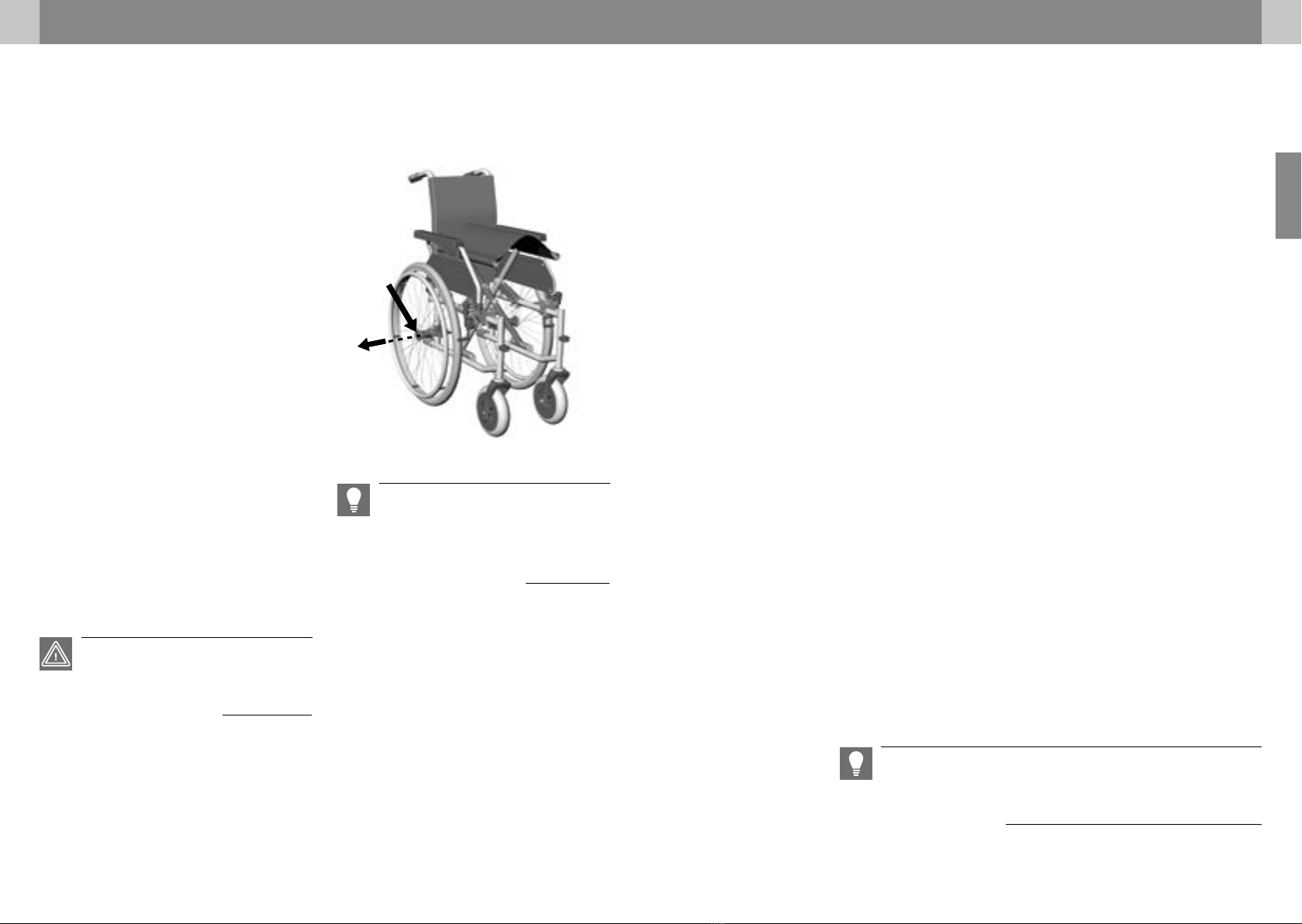
4.11 Removing and attaching rear
wheels
It can be useful to remove the rear wheels when
transporting the wheelchair or making adjust-
ments.
Removing a rear wheel:
1. Use your thumb to press the lock button of
the quick-release axle in the centre of the
wheel hub (1, fig. 15).
2. Put your other fingers between the spokes.
3. Pull the rear wheel with the quick-release
axle out of the axle holder (2, fig. 15).
Attaching a rear wheel:
1. Use your thumb to press the lock button of
the quick-release axle.
2. Position the rear wheel on the wheelchair
and insert the quick-release axle into the
mount until it engages.
3. Check whether the quick-release axle is
correctly engaged.
2
1
4 USING THE WHEELCHAIR
WARNING
After attaching the wheels, always verify that
the lock has engaged correctly.
NOTE
If you hold down the lock button when atta-
ching the rear wheels it is easier to insert the
quick-release axle in the mount.
fig. 15
22 23
TOMTAR MR-S/MR-LG user manual / version 3.1 EN
EN
4 USING THE WHEELCHAIR
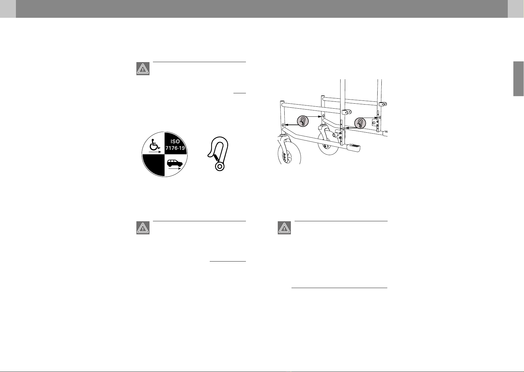
Attaching the wheelchair
restraint systems
Only a 4-point wheelchair restraint system with
lashing straps that is certified in line with
ISO10542 and designed for the total weight of
the wheelchair must be used to secure the TOM-
TAR MR-S/ MR-LG without a power hub.
The 4 lashing strap anchor points on the wheel-
chair are labelled with a hook symbol (see exam-
ple in illustration (A) and (B)).All 4 anchor points
must be used. It is mandatory to position the
wheelchair in the direction of travel in line with
ISO10542 (WTORS). Under no circumstances
must the wheelchair be strapped in place using
other attachment points (e.g. anti-tip bar, arm-
rests). No modifications must be made to the
transport anchor points of the wheelchair with-
out the permission of DIETZ.
The wheelchair restraint system must be installed
in the vehicle in line with the manufacturer’s as-
sembly instructions.
(A) Front anchor points on the wheelchair
(B) Rear anchor points on the wheelchair
(A) (B)
WARNING
The TOMTAR MR-S/ MR-LG is tested in line with
the ISO standard 7176-19 / ISO10542 in the
direction of travel. For reasons of safety, it must
not be used/attached with the wheelchair user
facing away from or sideways to the direction of
travel.
fig. 17
4 USING THE WHEELCHAIR
Wheelchair as a car seat
Wheelchairs are not designed to be used as car
seats and cannot provide the same level of
safety as a regular seat in a car, no matter how
well the wheelchair is fastened in the respective
vehicle. DIETZ therefore recommends to seat
wheelchair users on regular vehicle seats when-
ever possible.
The TOMTAR MR-S/MR-LG wheelchair complies
with ISO 7176-19 and is therefore suitable for
use as a seat for transporting passengers in mo-
tor vehicles. It accordingly is labelled in line with
ISO7176-19.
Tests were conducted using a H3 50% dummy
(78 kg) and a headrest.
Passenger cars designed for transporting wheel-
chair users while seated in a wheelchair have to
have a wheelchair space in accordance with the
German Road Traffic Licensing Regulation (St-
VZO). All wheelchair spaces in a vehicle have to
be provided with a wheelchair and wheelchair
occupant restraint system capable of restraining
the wheelchair and its occupant. The vehicle
owner and driver must provide in-car restraint
systems that comply with the ISO 10542 stan-
dard and ensure that they are used correctly.
ISO 7176-19
Crash-tested label
WARNING
Failure to obverse these instructions can result
in severe bodily injury and danger to life!
WARNING
Always ask the carrier whether the respective
vehicle is designed, insured and equipped to
carry a person in a wheelchair..
fig. 16
24 25
TOMTAR MR-S/MR-LG user manual / version 3.1 EN
EN
4 USING THE WHEELCHAIR
P Remove any components that can easily
come free from the wheelchair, such as a
therapy tray or walking aids etc., before
beginning the journey. Keep them in a
suitable safe place.
P Swivelling/adjustable-height leg rests
must not be raised when the user is
being transported whilst seated in the
wheelchair and the wheelchair is secured
by a restraint system and safety belt.
P Adjustable backrests must be put in the
upright position.
P The wheelchair user’s safety during
transport depends on the care with
which the restraint system has been
secured. The person having secured the
restraint system must be trained or
instructed in the use of the system.
Wheelchairs that have been involved in an acci-
dent must be checked by a DIETZ service techni-
cian before any further use.
4 USING THE WHEELCHAIR
Wheelchair user restraint system
First attach the wheelchair restraint system. Next,
the wheelchair user is secured using a suitable
restraint system in line with ISO 10542.
When doing so, the following must always be
ensured:
P Fasten the shoulder and lap belt. Both of
these belts must be fastened quite
tightly, but not so tight as to cause
discomfort to the wheelchair user and
must not be twisted.
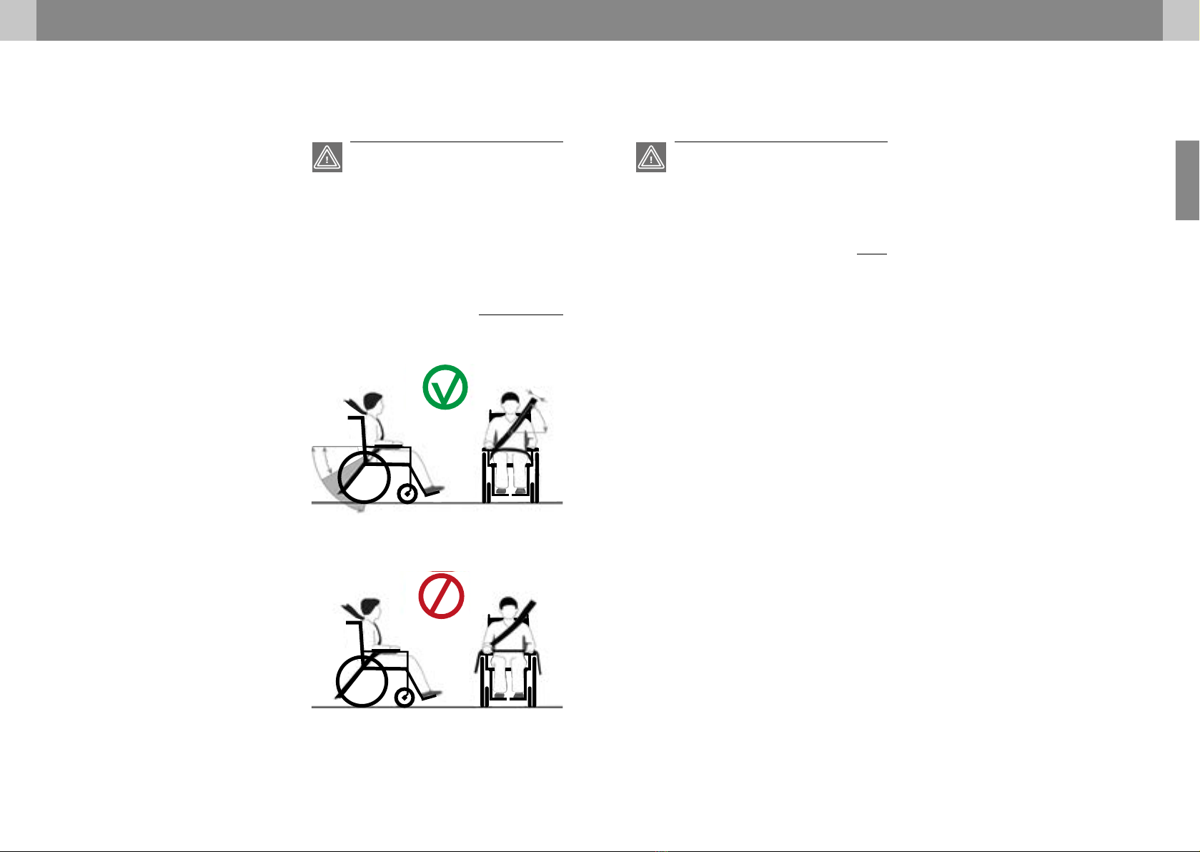
P The upper part of the safety belt must
run across the torso and shoulder/
collarbone.
P The lap belt must run at an angle of 30°
to max. 75° from the horizontal but
under no circumstances greater than 75°
(fig. C).
P Safety belts must not be routed over
components of the wheelchair, such as
armrests or wheels, which would hold it
away from the body. (fig. D).
P Only products that are certified in line
with ISO 7176-19/ISO 10542 or DIN
standard 75078 and appropriately
identified by their manufacturer may be
used as restraint systems.
P The wheelchair’s parking brakes must be
fully engaged throughout the drive.
100 mm
55°
30°
75°
100 mm
55°
30°
75°
(C) Correct attachment of the safety belts
(D) Wrong way to attach the safety belts
WARNING
The geometry of the anchor points (or of the
attachment system) must be adjusted with the
same precision as the user’s straps to ensure
safe transport in a vehicle with a user seated in
the wheelchair. Non-observance of these requi-
rements can put the wheelchair user’s life at
risk in the event of an accident.
fig. 18
fig. 19
WARNUNG
A therapeutic headrest provided on the wheel-
chair serves to support the head posture during
regular operation and cannot replace a car sui-
table headrest for use in a motor vehicle.

26 27
TOMTAR MR-S/MR-LG user manual / version 3.1 EN
EN
5 INDIVIDUAL ADJUSTMENTS
5.2 Adjustable backrest
(only TOMTAR MR-LG)
The TOMTAR MR-LG is equipped with a Velcro
adjustable backrest as standard. It can be adjust-
ed to suit your requirements. (fig. 21)
To do so, open the back strap’s Velcro fastener
under the seat pad and fold it forwards along
with the backrest upholstery. Now release the
Velcro strap (1). Then you can Velcro (1) the
straps together in the desired position (2). The
Velcro strap must overlap by at least 10 cm. Start
with the lowest strap. Finally, fold the back strap
backwards again and fasten it in place using the
Velcro fastener.
5.3 Armrests
The length and height of the armrests can be ad-
justed. (fig. 22)
1. From below, loosen the two Phillips screws
with which the armrest is attached to the side
panel. (1)
2. Adjusting the length (100 mm): Slide the
armrest backwards or forwards using the
threaded inserts provided (adjustable in 25-
mm stages). (2).
3. Adjusting the height (30 mm): Remove the
armrest and insert one or both height adapt-
ers (15 mm) between the tube of the side
panel and the armrest (3).
4. Attach the armrest with the two Phillips
screws.
fig. 21
fig. 22
5 INDIVIDUAL ADJUSTMENTS
5.1 Lower leg length
1. Loosen the bottom screw joint on the leg rest
(1, fig. 20) by one rotation.
2. Grip the footplate and pull it down or push it
up until the desired position is reached (2, fig.
20), but not above the max./min. label.
3. Tighten the threaded connection securely
again (1, fig. 20).
4. Check whether the lower leg length is cor-
rectly set: The thighs must be horizontal when
the feet are placed on the foot plates.
IMPORTANT INFORMATION ON ADJUSTMENTS
Accessories are sometimes required for the settings described below. Only original accessories from
DIETZ may be used. Only then is the compliance and thus the safety of the product guaranteed.
When setting up a new user for the first time, all wheelchair adjustments must be carried out by qual-
ified specialists so that correct positioning and safety can be guaranteed.
Tools
WARNING
Complex adjustment tasks that can result in a
risk of accident if not performed correctly must
only be conducted by designated specialist staff
and are labelled accordingly. “Only to be per-
formed by specialist staff”
This particularly applies to adjusting the brakes
and for settings that affect the stability of the
wheelchair.
fig. 20
Tools are required for some of the individual
setting tasks and checks on the TOMTAR
MR-S/MR-LG:
Allen key sizes 4, 5 & 6
Open-end wrench AF 10
cross tip screwdriver (size 2)
1
2
1
2
3
2
1

28 29
TOMTAR MR-S/MR-LG user manual / version 3.1 EN
EN
5 INDIVIDUAL ADJUSTMENTS
5.6 Seat height adjustment
Only to be performed by specialist staff:
The wheelchair is delivered with the seat at a
height of 510 mm. Alternative seat height set-
tings of 485mm and 460 mm can be selected
using bore holes in the wheel forks and the
wheelchair frame.
Tools: Allen key size 6 andopen-end wrench AF
10
Holes to be used in the front wheel fork
(1, fig. 26).
1.
Seat height 51 > Lower bore hole in the wheel forks
2.
Seat height 48.5 > Middle bore hole in the wheel
forks
3.
Seat height 46 > Upper bore hole in the wheel forks
The wheelchair frame has 5 bore holes for seat
height adjustment using the rear wheel adapter
(2, fig. 28). Bore holes provided:
4. Seat height 51 > 2nd + 3rd hole from the bottom
5. Seat height 48.5 > 3rd + 4th hole from the bottom
6. Seat height 46 > 4th + 5th hole from the bottom
To do this, loosen the fastening screws of the rear
wheel adapter (2, fig. 27) and adjust it to the de-
sired height. Tighten the screws again.
WARNING
Altering the seat height means the parking bra-
kes will have to be readjusted (see
chapter 5.7).
WARNING
Ensure that all screws have been tightened af-
ter the adjustments have been made.
fig. 26
fig. 27
5 INDIVIDUAL ADJUSTMENTS
5.5 Seat depth
The wheelchair is delivered with the maximum
possible seat depth of 440 mm. To reduce the
depth of the seat, first remove the leg rests (see
chapter 4.5). Next, open the Velcro straps on the
left and right under the seat pad (1, fig. 24).
Now attach the Velcro straps to the bottom of
the seat pad extension so that they no longer
enclose the wheelchair frame (2, fig. 25). Fold the
extension under the seat and fasten the Velcro
straps to secure it there (3, fig.25).
Carry the procedure out in the opposite sequence
to increase the seat depth.
5.4 Adjusting the push handle
(only TOMTAR MR-LG)
On the TOMTAR MR-LG, the height of the push
handle can be adjusted to suit the requirements
of the accompanying person.
1. First, loosen the clamping lever screw on the
back of the backrest. (1, fig. 23).
2. Now you can pull the tube of the push han-
dle up into the desired position. (2, fig. 23).
Screw the clamping lever screw back into one of
the three bores provided. Ensure that the clamp
lever screws are tight.
fig. 23
fig. 24
fig. 25
1
1
2
1
1
2
2
3
2

30 31
TOMTAR MR-S/MR-LG user manual / version 3.1 EN
EN
5 INDIVIDUAL ADJUSTMENTS
5.9 Wheelbase extension (optional)
Only to be performed by specialist staff:
Moving the rear wheel backwards extends the
wheelbase and therefore improves the stability
of the wheelchair.
Tools: Allen key size 4 and open-end wrench AF
10.
If the wheelbase is extended, the parking brake
must be modified to ensure that the distance be-
tween brake pin and tyre casing is 3-5 mm at the
narrowest point as intended.
First, remove the rear wheels (see chapter 4.12).
This secures the wheelchair against tipping over.
Next, loosen the two screw joints of the adapter
(1, fig. 30) and pull the screws out completely.
Then, rotate the adapter vertically by 180° (2, fig.
30, 31) and fix it in place. Ensure that all screws
are firmly tightened.
On the model with the drum brake, the brake ca-
ble must be detached before dismantling the
adapter. After, the adapter including the drum
brake is rotated vertically by 180°. After mount-
ing the adapter, the brake cable must be corre-
spondingly relocated and fixed in place again.
To modify the parking brake as necessary, first
remove the locking brakes.
Then, swap the mounting bracket of the parking
WARNING
Converting the wheelbase means all brakes will
have to be readjusted (see chapter 5.7 and 5.8).
fig. 30
fig. 31
5 INDIVIDUAL ADJUSTMENTS
5.7 Parking brakes
Only to be performed by specialist staff:
The distance between the brake pins and the tyre
casing must be 3-5 mm at the narrowest point
when the brake mechanism is fully open
(1, fig. 28).
Tools: Allen key size 4 and open-end wrench AF
10. Loosen the screw to adjust/correct the dis-
tance (2, fig. 28). Then push the brakes into the
correct position. Now retighten the screw and
check the function of the brakes. When the
brakes are applied, it must not be possible to
push the wheelchair.
5.8 Drum brake (optional)
Only to be performed by specialist staff:
Adjust the braking force using the adjusting
screw (1) on the brake cable to achieve an opti-
mum braking effect. (fig. 29)
Tools: Open-end wrench AF 10
Increase the braking force by unscrewing the ad-
justing screw (1). Loosen the lock nut and un-
screw the adjusting screw until you hear grinding
noises from the turning wheel. Then screw in the
adjusting screw until the grinding noises stop.
Once you have finished adjusting the settings,
the adjusting screw is fixed by tightening the
lock nut.
WARNING
Ensure that the drum brakes are evenly adjus-
ted on both sides of the wheelchair.
fig. 28
fig. 29
1
2
2
1
2
1
32 33
TOMTAR MR-S/MR-LG user manual / version 3.1 EN
EN
2
1
3
1
2
4
5.11 Angle-adjustable foot plates
Tools: Allen key size 5
To change the angle, first loosen the Allen screw
(1, fig. 35) and pull the foot plate slightly inwards
until the lock is released. Now adjust the foot
plate to the desired angle (2, fig. 35) then tighten
the Allen screw again.
5 INDIVIDUAL ADJUSTMENTS
5.12 Safety belt (optional)
Only to be performed by specialist staff:
An optional belt can be installed. This secures
and stabilises the person seated in the wheel-
chair. It prevents the person from tipping for-
wards out of the wheelchair.
Tools: Cross tip screwdriver
The safety belt is attached to the most rear screw
connection of the seat pad. To do so, loosen the
Velcro on the side of the seat pad (1, fig. 36).
Now you can loosen the back screw on the seat
pad. Position the end of the lap belt with the eye
precisely over the bore hole in the seat pad. Now
screw the seat pad and the lap belt together (2,
fig. 36) using the screws supplied with the lap
belt. Ensure that the screw has been tightened.
1
2
fig. 36
fig. 37
05 INDIVIDUAL ADJUSTMENTS
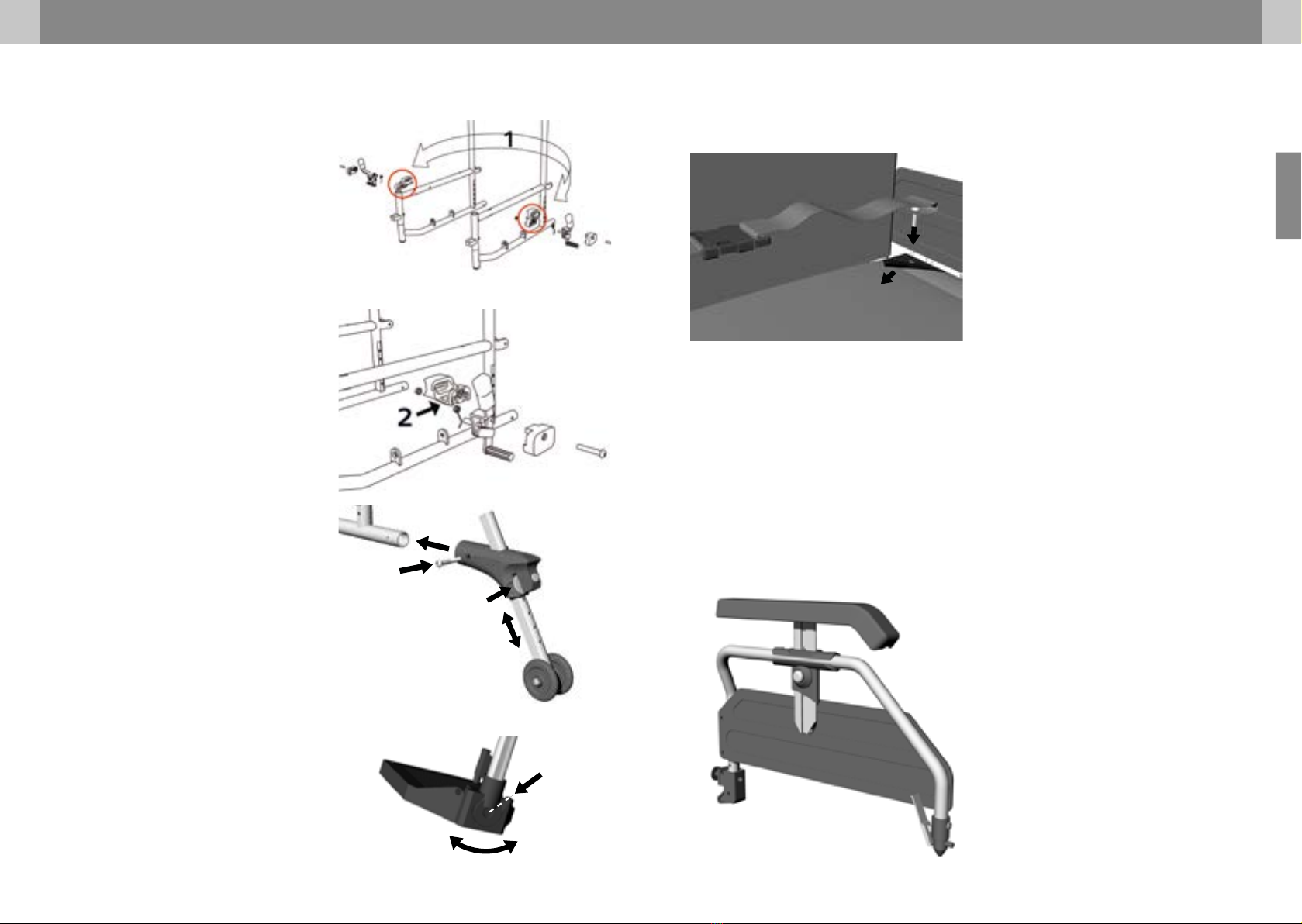
5.10 Anti-tipping supports (optional)
Only to be performed by specialist staff:
(fig. 34) Tool: Open-end wrench AF 10
Remove the rubber tilting aids to insert the attach-
able anti-tipping supports in the lower rear frame
tube (1). The supporting wheels are attached to
the metal tube and secured with a screw (2).
The height of the wheels can be adapted to the
wheelchair and the anti-tipping supports can be
pushed upwards. This is useful if an accompany-
ing person is pushing the wheelchair and needs
to get past obstacles. To do so, pull the red clamp
bracket towards yourself (3) and push the tube
up or down (4) along the fixture.
brake from one side to the other side and rotate
it horizontally by 180°. (1, fig. 32).
The assembly retainer (2, fig. 33) is now posi-
tioned to the rear (180° horizontal). Next, mount
the parking brake on the wheelchair.
Please make sure that the parking brakes are
correct adjusted. (see chapter „Parking brakes“) fig. 32
fig. 33
fig. 34
fig. 35
1
5.13 Height-adjustable side panel
(optional)
To replace the side panel, proceed as described
for the standard side panel in the chapters “Re-
moving the side panels/armrests” and “Swivel-
ling the side panels/armrests”.
You can adjust the armrest height using the ex-
ternal push button (1, fig. 37) by adjusting the
height while pressing the push button. The arm-
rests can be adjusted to 8 heights in 1-cm steps
from 230 mm to 300 mm above the seat’s sur-
face. The length of the armrest pad is 305 mm
measured from the back frame.

34 35
TOMTAR MR-S/MR-LG user manual / version 3.1 EN
EN
05 INDIVIDUAL ADJUSTMENTS
5.16 Therapy tray (optional)
The therapy tray is mounted using a set of rails.
For further information, see the assembly instruc-
tions delivered along with the therapy tray.
fig. 40
fig. 41
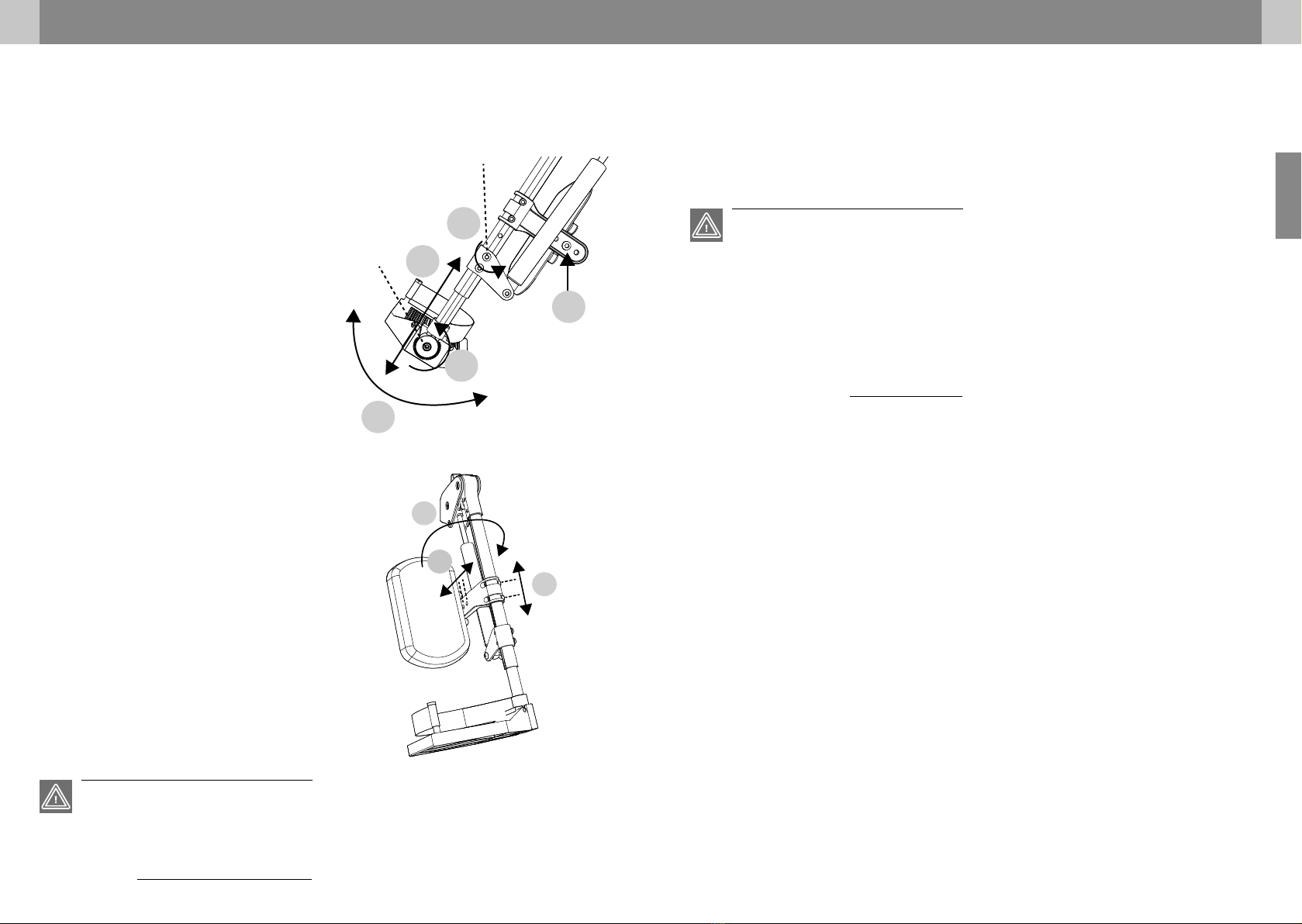
5.14 Amputee support (optional)
1. Remove the leg rest (chapter 4.5).
2. Grasp the amputation board by the cushion
and insert it from above into the frame tube
(1, fig. 38).
Adjusting the amputee board angle:
1. Release the clamping lever counterclockwise
(2, fig. 38).
2. Move the amputee board into the desired
position.
3. Tighten the clamping lever in a clockwise
direction.
Adjusting the height of the amputee board:
1. Loosen the two socket head screws (3, fig.
38).
2. Take hold of the amputee board by the pad
and push it upwards or downwards until the
desired position has been achieved. Finally,
tighten the screws again.
5.15 Brake lever extension (optional)
To be performed by a specialist dealer: The
brake lever extension is used to make it easier to
transfer force to the brake. (fig. 39)
1. Remove the standard brake lever by pulling it
upwards (1). The mounting hole for the brake
lever extension can now be seen.
2. Attach the brake lever extension to the
exposed mounting hole using a Phillips
screwdriver and a size 10 open-end wrench.
05 INDIVIDUAL ADJUSTMENTS
fig. 38
fig. 39
5.17 Elevating leg rest (optional)
The calf pad have to be installed before using for
the fi rst time. Use the enclosed 5 mm Allen
screw and nut and install in the third position
hole on the calf pad holder (see 5, fig. 43/ fig. 44
s. 36/37).
When attaching the leg rest to the wheelchair,
proceed in the same way as with a standard leg
rest (see the wheelchair user manual).To fold the
leg rest, move the locking lever forwards whilst
rotating the leg rest to the side (1/2, fig. 41).
Adjusting the angle of the leg rest 5°- 68°
1. Press the release lever for the pneumati
spring forwards (3/4, fig. 41). The knee angle
falls from 68° to 5° as long as the release
lever is kept pressed.
2. To set an angle, let the release lever of the
pneumatic spring go at the desired position.
3. The grid lines can be used as an orientation
for the set angle (fig. 42).
4. Press the release lever forwards and push the
leg rest down at the same time to increase
the knee angle (fig 41).
21
3
4
5°- 68°
fig. 42
WARNING
Risk of trapping: there is a risk of trapping on
moving parts (e.g. calf pad, pivot lever)
Risk of injury: do not stand on the foot plate or
carry the wheelchair by the leg rests. They are not
intended to bear the full weight of one person.
3
2
1
1
36 37
TOMTAR MR-S/MR-LG user manual / version 3.1 EN
EN
fig. 44
fig. 43
5.18 Accessories and add-ons from
external suppliers
In general only original accessories from DIETZ
may be used. If third-party products are installed
on the wheelchair, responsibility for the safety of
the product passes to the person who installs the
accessories or carries out the installation.
The compliance of the combination of accesso-
ries or add-on and product is then new, and must
be declared by the person who attaches it. The
compliance declared by DIETZ according to MDR
2017/745, Annex II expires.
WARNING
Should add-ons or accessories that are not sold
by DIETZ are used, the safety of the product can
not be guaranteed.
If accessories or add-ons are added to the
wheelchair, then the safety instructions in the
operating instructions for the accessories or
add-ons must be observed.
WARNING
The calf pad can be swivelled outwards with the
holder to relieve the calf and give the leg more
room (3, fig. 44).
Adjusting the lower leg length:
1. To adjust the length, loosen the Allen screw 4
mm (A, fig. 43) by a few rotations (1, fig. 43),
but do not loosen it fully.
2. Then pull/slide the foot plate to the desired
length (2, fig. 43). Pay attention to the min-
imum gap of 40 mm between the foot plate
and the ground.
3. To lock it in place, tighten the screw (A, fig.
43) again fi rmly. Make sure that the screw
engages in the interior carriage.
Adjusting the foot plate angle:
1. Loosen the Allen screw 5 mm (B & 3, Fig.3).
2. Pull the foot plate off on the inside.
3. Re-insert the foot plate at the desired angle
(4, fig. 43).
4. Finally, fasten the foot plate in place again-
with the Allen screw B.
Positioning the calf pad:
1. Loosen the 2 Allen screws 5 mm on the hold-
er to adjust the height. Following adjustment,
fi x the screws back into the hole pattern in
30 mm steps (1, fig. 44).
2. 2. Loosen the Allen screw 5 mm to enable
depth adjustment. Following adjustment, fix
the screws back into the hole pattern in 20
mm steps (2, fig. 44).
1
4
2
3
A
B
5
2
1
3
38 39
TOMTAR MR-S/MR-LG user manual / version 3.1 EN
EN
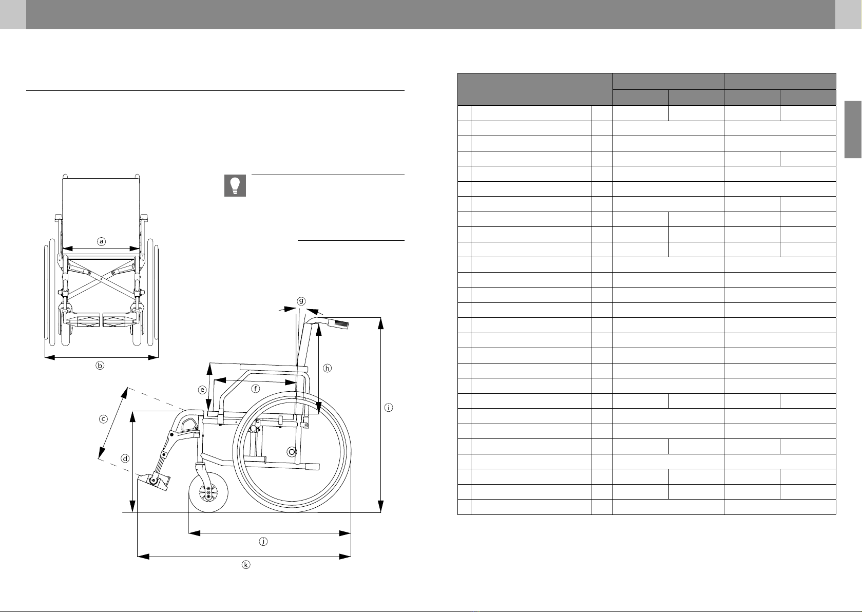
06 TECHNICAL DATA
Technical specifications TOMTAR MR-S TOMTAR MR-LG
Min. Max. Min. Max.
kTotal length with leg rests mm 1052 1108 1052 1108
jTotal length without leg rests mm 800 800
bTotal width1mm 590/620/650/680/710 590/620/650/680/710
iTotal height mm 945 945 1030
jLength folded mm 800 800
Width when folded mm 310 310
iHeight folded mm 945 945 1030
Total mass kg 18.1 20.3 15.2 16.5
Total weight with drum brake kg 19.2 20.5 16.2 17.1
Mass of the heaviest part2kg 10.8 12.0 8.2 9.5
Static stability downhill3°16 16
Static stability uphill3°17 17
Static stability sideways3°15 15
Seat plane angle ° ° 2 2
fEffective seat depth (adjustable) mm 400 (450) 400 (450)
aEffective seat width mm 395-515 395-515
dSeat surface height (front edge) mm 460 / 485 / 510 460 / 485 / 510
gBackrest angle ° 2 2
hBackrest height mm 430 390-480
cFootrest to seat distance mm 362 512 362 512
Leg rest angle relative to seat °110 110
e Armrest to seat distance (adjust.) mm 220 (235/250) 220 (235/250)
Armrest length from back frame mm 280 380 280 380
Push rim diameter mm 525 525
Horizontal position of axle mm -30 30 -30 30
Minimum turning radius mm 1270 1290 1292 1312
Maximum user weight4kg 130 130
1 The total width of 71 cm exceeds the recommended dimension of 70 cm stipulated by DIN EN 12183.
2Wheelchair weight minus removable parts (here without rear wheels, without side panels, without leg rests)
3 The static stability indicates the wheelchair’s tipping resistance on slopes and gradients.
4 Maximum user weight including load/The weight of the load reduces the maximum user weight.
06 TECHNICAL DATA
WHEELCHAIR DIMENSIONS
The dimensions given here refer to the standard configuration of the wheelchair and may vary depend-
ing on the wheelchair model and configuration.
NOTE
All dimensions taken on textile parts (e.g. back
upholstery) are to be understood with a tole-
rance of +/– 1 cm.
Other manuals for MR-S
1
This manual suits for next models
1
Table of contents
Other Tomtar Wheelchair manuals


