TOP DC CUT 20 User manual

PLASMA CUTTER
OPERATOR'S MANUAL
www.topacdc.com Amazon Store Facebook
MODEL: CUT 20

CONTENTS
Please save these instructions. This manual contains important safety and operating
instructions. Read all instructions and follow them with each use of this product.
S
SERVICE
AFETY INFORMATION 1-3
SPECIFICATIONS 4
SET-UP 4-5
OPERATION 5-6
MAINTENANCE 7-8
9-10
TROUBLE SHOOTING
…………...……………………………….…………….…………….
……………………...……………………………….……………….……………….
10
……………………...……………………………….……………….………………
……………...……………………………….………….……
……………...……………………………….…………….…………….
.……………………………….……………….……………….
………………..……………...……………………………….………….……
SAFETY INFORMATION
1
In this manual, on the labeling, and all other information provided with this product:
DANGER indicates a hazardous situation which, if not avoided, will result in death or
serious injury.
WARNING indicates a hazardous situation which, if not avoided, could result in death
or serious injury.
CAUTION indicates a hazardous situation which, if not avoided, could result in minor
or moderate injury.
NOTICE is used to address practices not related to personal injury.
People with pacemakers should consult their physician(s) before using. Electromagnetic
fields in close proximity to heart pacemaker could cause pacemaker interference or
pacemaker failure. In addition, people with pacemakers should:
• Avoid operating alone.
• Do not use with Power Switch locked on.
• Properly maintain and inspect to avoid electrical shock.
• Any Power Cord must be properly grounded. Ground Fault Circuit Interrupter (GFCI)
should also be implemented – it prevents sustained electrical shock.
ELECTRIC SHOCK CAN KILL!
• Do not touch any electrical components that may be live.
• Separate yourself from the Plasma Cutter circuit by using insulating mats to prevent
contact from the work surface.
• Improper use of a Plasma Cutter can cause electric shock, injury and death! Read
all precautions described in this manual to reduce the possibility of electric shock.
READ INSTRUCTIONS!
• Thoroughly read and understand this instruction manual before using the
Plasma Cutter.
• Keep this instruction booklet.

• The Plasma Cutter power switch is to be in the OFF position and the power supply
is to be disconnected when performing any maintenance or consumable changes.
• Always wear dry, protective clothing and leather welding gloves and insulated footwear.
• Always operate the Plasma Cutter in a clean, dry, well-ventilated area. Do not operate
the Plasma Cutter in humid, wet, rainy or poorly ventilated areas.
• Be sure that the work piece is properly supported and grounded prior to beginning an
electric Plasma Cutter operation.
•The electrode and work (or ground) circuits are electrically “hot” when the welder is on.
Do not touch these “hot” parts with your bare skin or wet clothing.
• Disconnect from power supply before assembly, disassembly or maintenance of the
torch or contact tip.
• Always attach the ground clamp to the piece to be welded and as close to the weld
area as possible. This will give the least resistance and best cut.
• Do not breathe fumes that are produced by the cutting operation. These fumes are
dangerous and can cause serious respiratory damage.
Keep your head and face out of cutting fumes.
• Always work in a properly ventilated area. Wearing an OSHA-approved respirator when
cutting is recommended!
ELECTROMAGNETIC FIELDS MAY BE DANGEROUS!
• Anyone with a cardiac pacemaker or other implanted medical device should stay away
•Exposure to electromagnetic fields while plasma cutting may have other health effects
from any plasma cutting before consulting a doctor.
Powerful electromagnetic fields emitted by Plasma Cutters can interfere with
operation, causing malfunction and possible death.
which are not known.
FUMES AND CUTTING GASES CAN BE DANGEROUS!
2
• Never cut coated materials including but not limited to: cadmium plated, galvanized,
lead based paints.

CUTTINGSPARKS CAN CAUSE FIRE OR EXPLOSION!
•Do not operate Plasma Cutter in areas where flammable or explosive vapors are
present.
• Always keep a fire extinguisher nearby while cutting.
• Use welding blankets to protect painted surfaces, dash boards, engines, etc.
• Ensure power supply has properly rated wiring to handle power usage.
• Do not use on or near combustible surfaces.
• Remove all flammable items within 35 feet of the cutting arc.
sparks. To prevent injury, wear approved safety glasses.
• Cutting, brushing, hammering, chipping, and grinding can cause flying metal chips and
3
• Use a shield with the proper filter (a minimum of #11) to protect your eyes from sparks
and the rays of the arc when cutting or when observing open arc cutting (see ANSI
Z49.1 and Z87.1 for safety standards).
• Use suitable clothing made from durable flame-resistant material to protect your skin.
Protect nearby individuals with a non-flammable barrier.
• If other persons are in the area of cutting use welding screens to protect bystanders
from sparks and arc rays.
ARC RAYS CAN BURN EYES AND SKIN!
• Electric cutting operations cause sparks and heat metal to temperatures that will
cause severe burns!
• Use protective gloves and clothing when performing any Plasma Cutter operations.
Always wear long pants, long-sleeved shirts and leather welding gloves.
• Make sure that all persons in the cutting area are protected from heat, sparks and
ultraviolet rays.
• Use additional face shields and flame resistant barriers as needed.
• Never touch work piece until it has completely cooled.
HOT METAL WILL BURN!
FLYING METAL CHIPS CAN CAUSE INJURY!

SPECIFICATIONS
SET-UP
4
Input Voltage 120VAC
15A plug
120VAC
20A plug
Output Range 10-16A 10-20A
Rated Duty Cycle 60%@16A 35%@20A
Maximum OCV 400V
Quality Cutting Thickness 3mm 6mm
Maximum Cutting Thickness 4mm 10mm
Input Air Pressure 45-55 psi
The rated Duty cycle refers to the amount of plasma cutting that can be done within a
measured amount of time. The Plasma Cutter has a duty cycle of 60% at 15 Amps.
It is easiest to look at your cutting time in blocks of 10 Minutes and the Duty Cycle being
a percentage of that 10 Minutes. If cutting at 15 Amps with a 60% Duty Cycle, within a 10
Minute block of time you can cut for 4 Minutes with 6 Minutes of cooling time allowed for
the cutter.
ELECTRIC SHOCK CAN KILL!
Disconnect from power supply before assembly or maintenance
• After a proper 20 Amp, 120 VAC, 60 Hz current source is determined, be sure the
appropriate circuitry and breakers are in place.
• DO NOT plug unit in at this time and make sure the Power Switch located on the upper
right corner of The Rear Panel is in the OFF position.
• Install a quick-disconnect air fitting compatible with your air line into the 1/4” NPT fitting
located on the upper left corner of the Rear Panel.
• Attach the Torch Air Supply Line to the lower right corner of the Front Panel by
threading in place. Note: “Finger-Tighten” securely but do not over tighten.
•Attach the Torch Switch Connector Cable to the Multi-Pin Connector located second
from right of the Lower Front Panel. Note that the semi-circular notch of the inner
female plug must align with the semi-circular male key of the metal shell. Push plug

securely in place then thread the metal locking ring in onto the metal shell. “Finger-
Tighten” securely but do not over tighten.
• Attach the Ground Lead located at the Lower Left Corner of the Front Panel. Note that
the semi-circular notch of the inner female plug must align with the semi-circular male
key of the metal shell. Push plug securely in place then rotate the plug 1/2 turn in a
Clockwise direction until it locks.
OPERATION
1. Before attempting to use this unit on an actual project or object of value, practice on
a similar material as there is a moderate learning curve necessary before achieving
proficiency in cutting.
2. Set the Air Pressure to the appropriate pressure with the Knob located at the rear
panel.
To set: Pull the Knob Shell outward to unlock, rotate it clockwise to raise pressure and
Counter-Clockwise to lower pressure. Push Knob Shell inward to lock in place.
3. The Pressure Indicating Gauge is located at the rearpanel, next to the Air Pressure
Knob and is set at 40 to 55 PSI depending on metal composition and thickness.
ARC RAYS CAN BURN SKIN AND EYES!
• Use a shield with the proper filter (a minimum of #11) to protect your eyes from sparks
and the rays of the arc when cutting or when observing open arc cutting (see ANSI
Z49.1 and Z87.1 for safety standards).
• Use suitable clothing made from durable flame-resistant material to protect your skin.
Protect nearby individuals with a non-flammable barrier.
CUTTING SPARKS CAN CAUSE FIRE OR EXPLOSION!
• Use a shield with the proper filter (a minimum of #11) to protect your eyes from sparks
and the rays of the arc when cutting or when observing open arc cutting (see ANSI
Z49.1 and Z87.1 for safety standards).
• Use suitable clothing made from durable flame-resistant material to protect your skin.
Protect nearby individuals with a non-flammable barrier.
present.
•Always keep a fi re extinguisher nearby while cutting.
• Do not operate Plasma Cutter in areas where flammable or explosive vapors are
5

7. To begin cutting, depress the Torch Trigger to ignite the pilot arc. The RED “ ”
indicator lamp should illuminate the tip of the torch must be
touching or within a short distance to the work piece to begin the cut.
DANGER: Plasma Arc consists of superheated, electrified air which will quickly and
violently vaporize almost anything in its path.
8. With practice, you will be able to exercise precise control over this extremely powerful
device, harnessing its energy to create clean, precise and intricate cuts in many forms of
steel and iron up to 1/8" thick.
9. While you practice, experiment with different speeds. You will find that thinner
materials will allow a faster motion while thicker materials will require a slower motion to
achieve a through cut.
10. A good form of practice is to attempt a series of straight lines while creating the
cleanest edge possible with a minimum of molten material remaining on the cut edge.
This minimizes the cleanup of the edge with a grinder or fi le. Another excellent
technique is to practice cutting your initials out of a piece of steel.
4. Place the Ground Cable Clamp on a clean, bare area of your workpiece. Scrape, wire
brush, fi le or grind a bare area if necessary to achieve a good ground.
5. Make sure the Tip is not making contact with anything or anyone then set the
“ON/OFF” switch to the “ON” position. The GREEN “ON” indicator lamp should illuminate.
6. The best results are achieved by holding the Tip at a 90° angle to the desired cut line
of your work piece.
• Ensure power supply has properly rated wiring to handle power usage.
•Do not use on or near combustible surfaces.
• Remove all flammable items within 35 feet of the cutting arc.
CUT 20 Plasma Cutter-Air Pressure and Amperage Settings
Metal Thickness 1/32" 1/16" 3/32" 1/8"
Amps 15 15 18 20
PSI 40 45 50 55
*NOTE: These settings are guidelines only and may need to be adjusted based on
your techniques and type of metal being cut.
6

MAINTENANCE
POWER UNIT CARE & MAINTENANCE
• The Plasma Cutter has a moisture separator which requires draining each time you
have completed work with the unit. This feature is located on the underside rear corner
and is drained by keeping the unit level and gently pulling down on the drain fitting
• Constantly inspect the torch tip for excessive erosion, molten metal accumulation
burning. If damaged, it must be replaced.
• Before each use, inspect ALL electrical connections, cables, supply line, torch, air
supply, housing and controls for damage. If any damage or wear is noted, DO NOT
USE THE UNIT.
• Always store the unit in a safe, clean and dry environment.
TORCH MAINTENANCE
The Plasma Cutter has a number of consumable parts that will need to be replaced
over time. If wear or slag build up is noticed on any of the torch components, replace
them immediately to avoid damage to the torch. Worn components will also contribute
to poor cutting and difficult arc starting.
7
1
2
3
4
5
6
7
10
8
9
11
12
13
14
15
36
34
33
32
31
27
30
25
26
24
23
22
21
18 17 16
28
29
19
20
35
8
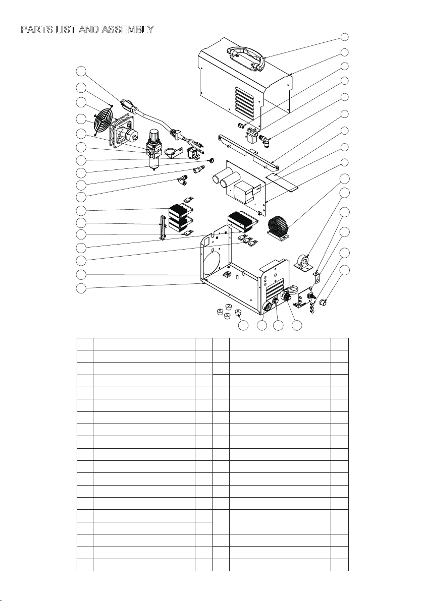
NO. Part Name QTY
1 Handle 1
2 Top Cover 1
3 Pneumatic Joint 1
4 Magnetic valve 1
5 Elbow 1
6 Bracket 1
7 High frequency PCB 1
8 Control PCB 1
9 Main PCB 1
10 Output choke 1
11 ARC PCB 1
12 Angle iron 1
13 Panel PCB 1
14 Chimney 3
15 Knob 1
16 Quick connector 1
17 Aviation plug 1
18 Quick connector 1
19 Foot pad 4
20 Bottom cover 1
21 PCB clip 1
22 Fast recovery diode 3
23 Rectifier heatsink 1
24 IGBT 2
25 Support 1
26 IGBT heatsink 2
27 Elbow 1
28 Connector 1
29 Convenient ring 1
30 Switch 1
31 Bracket 1
32 Reducing Valve 1
33 Header 1
34 DC fan 1
35 Fan cover 1
36 Power cable 1
NO. Part Name QTY
PARTS LIST AND ASSEMBLY

TROUBLESHOOTING
9
Trouble Experienced Possible reasons Likely Solutions
All LEDs OFF when turn
ON the machine
1. No input power
2. Power Switch is OFF
1. Verify that circuit breaker
hasn’t been tripped in
your main power panel.
Resent if needed
2. Ensure “Power Switch”
is in the on “1” position.
Green LED flashing Input voltage too low or too
high Verify input power source
Yellow LED solid, and no
output, fan operating
properly
Machine has reached its
duty cycle
Allow machine to cool down
with fan running.
Yellow LED flashing Insufficient air pressure or
air flow
Make sure input air pressure
is within 45-55psi
Red LED flashing
Shield cup not installed in
position or consumables
missing or consumables
worn badly
Check consumables and
shield cup are installed
properly. Replace
consumables if they are
worn badly.
Improper ground
connection
Make certain that the work
piece is contacted properly
by the Earth Clamp and that
the work piece is properly
cleaned near the Earth
Clamp and the welding
location
Improperly sized or
excessively worn Nozzle
Verify that Nozzle is the
proper size for the Cutting
Torch used. Check that the
hole in the tip is not de-
formed, enlarged, or dirty. If
needed, replace Nozzle with
proper size and type
Output current is too low Increase output current
through clockwise adjusting
the knob. Make sure proper
input power is supplied.
Material being cut is too
thick
Refer to SPECIFICATIONS
to choose material with
proper thickness. Or change
to a more powerful plasma
cutter to cut the material with
thickness exceeds the limit.
Cutting speed is too fast slower torch travel speed
Torch is too tilted
Adjust cutting angle and
make sure torch head is
vertical to the workpiece
Consumables are worn out
Check the consumables
condition and replace the
worn parts if necessary
Insufficient cutting
penetration
does not igniteArc

10
Excessive slag formation
Consumables are worn out
Replace worn consumables,
then reassemble Torch
tightly
Improper cutting speed
Increase cutting speed if
slag formed at the bottom, or
decrease if slag formed at
the top of workpiece.
No gas flow
Nozzle Plugged
Clean Nozzle. If damaged,
replace
Air supply hose blocked
Check air supply hose, and
hose within Cutting Torch
cable
Cutting arc not stable
Loose Torch cable or
Ground Clamp cable
Check to ensure that all
connections are tight.
Unstable line voltage
Check the line voltage and, if
there are problems with the
wires, have a licensed
electrician remedy the
situation.
Cutting current is too low
Increase cutting current
through turning the knob
clockwise.
Torch travels too fast
Slow down the cutting speed
Torch consumables worn
out
Check nozzle, shield cup, or
electrode, replace if needed.
Thank you for purchasing our plasma cutter. Your purchase includes our free 1-year limited
warranty. If you have any questions or issues about your product, Welcome to contact us at
topacdc01@gmail.com
Please have your order number available when asking for support.
SERVICE
Table of contents


