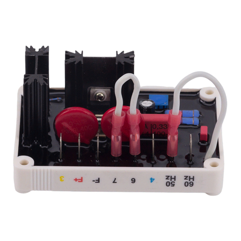
VOLTAGE ADJUST RHEOSTAT (V)
An internal screwdriver preset (V) provides
coarse adjustment of generator output voltage.
A clockwise adjustment of V increases voltage.
Thevoltageregulatorisshippedfromthefactory
with a link across terminals P and Q. If a re-
mote voltage adjust rheostat is used, the link
should be removed and the rheostat connected
to P and Q. A 1 kilo-ohm, 0.5 W potentiometer
will provide a 'fine' voltage range adjustment of
approximately ±10% over most of the coarse
range of adjustment. See Figure 5,
Intercon-
nection Diagram
.
V/HZ "CORNER FREQUENCY" SELECTION
For50 Hzsystems,theregulatoris presetat the
factory for a47 Hz "corner frequency" witha link
fitted across terminals “50". If operation at 60
Hz is required, this link should be removed; the
"corner frequency" is now set to 57 Hz. Do not
operate the system at 60 Hz with the 50 Hz link
still in place.
OVEREXCITATION SHUTDOWN
Overexcitation shutdown is provided to remove
output excitation should the regulator output
voltage exceeds 52 ± 2 Vdc for a sufficient time.
Theinverse-time-delay curve isshownin Figure
2. For voltages above 95 ±5 Vdc, there is a
second and much shorter inverse time curve.
Afteroutputpowerisremoved,theregulatorcan
be reset by decreasing the input voltage to less
than 6 Vac for a minimum of 2 seconds. This
may be accomplished by stopping the prime
mover or interrupting the regulator input by
means of a reset switch.
In cases where the generator is operating in a
parallel mode, it is sometimes considered
undesirable to allow the regulator to shut down,
whichmay cause the generator to be ”motored.”
Terminals N and D may be linked together to
prevent overexcitation shutdown. Note, how-
ever, that continuous running at output levels
greater than the continuous rating may result in
eventual regulator failure, and that other means
should be employed to protect the system.
OPERATION
GENERAL
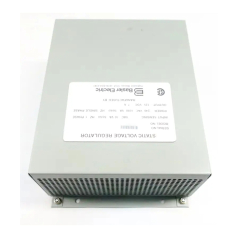
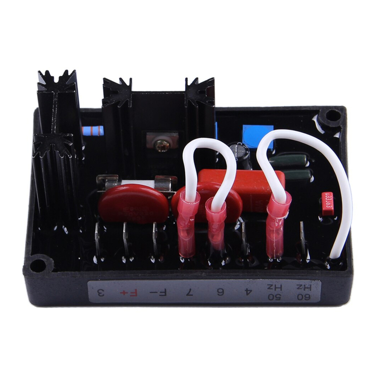
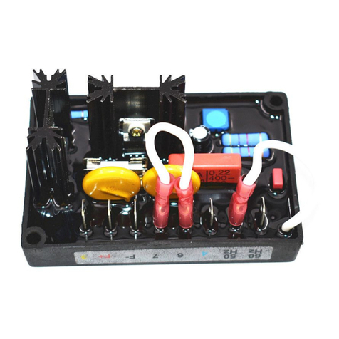
The following system operation procedures
provide instructions for adjusting the AEC 42-7
voltage regulator. Symptoms resulting from a
faulty regulator and certain generator system
problems are included, together with suggested
remedies.
Complete the followingsteps before proceeding
with system startup.
PRELIMINARY SETUP
a. Verify that the voltage regulator
specifications conform with the generator
system requirements.
b. Ensure that the regulator links are fitted
correctly where required, as follows.
(1) If the remote voltage adjust rheostat is
not required, ensure terminals P and
Q are linked together.
(2) If a 57 Hz corner frequency for 60 Hz
systems is desired, ensure the”'50 -
50" link is removed. If a 47 Hz corner
frequency for 50 Hz systems is
desired, ensure the “50 - 50" link is
connected.
(3) If the system is to be run in parallel,
consider whether shutdown of the
generator's excitation is acceptable. If
not, ensure that the link between
terminals N and D is in place.
c. Ensure that the voltage regulator is cor-
rectly connected to the generator system:
F+ to field positive, F- to field negative, and
terminals 3 and 4 to the auxiliary winding
supply. It is vital that the sensing con-
nections are correctly made to all 4 wires
U, V, X, and Y. Ensure that the metal ring
tag at one mounting hole is bonded to
ground via either a metal screw or short
length of cable.
d. Install the fuses as directed in the previous
section.
e. Set the regulator and external voltage
adjust, if used, as follows:
Regulator Volts Adjust 'V' Fully CCW
Remote Volts Adjust Centered
Stability Adjust 'S' Centered
SYSTEM STARTUP
a. Perform the preliminary setup procedure
checking wiring carefully.
b. Start prime mover and bring up to rated
speed.
RESULT: The voltage should build up to less
than nominal value.
c. Slowly adjust the regulator voltage adjust V
until the generator output voltage reaches
the nominal value. Should a low frequency
oscillation or hunting be present on the
generator output voltage, adjust stability
control S to cause this to be damped out.
In general, clockwise increases the
stability. But in some cases, too far CW
may start to reduce stability again, and will
invariably slow the response of the
generator to load changes. An optimum
setting method is to adjust S slowly CCW
until the generator voltage just starts to
become unstable. Then turn it up to ¼ turn
CW from that position.
d. If used, adjust the external voltage adjust
rheostat to fine trim the voltage to the exact
value desired.
RESULT: Voltage should now have built up
and be stable at the desired value. If voltage
does not build up to rated value, check that
there is no short circuit or excessive load
present on the generator lines. If a minimum
residual of 6 Vac is not present, perform “Field
Flashing” as ex-plained later.
e. Check regulator under normal operating
and loading conditions.
RESULT: Voltage regulation should be better
than ±1.0% no-load to full-load. If regulation is
not within this range, check the following:
(1) Voltage reduction under loads of cosq >
0.0 may be due to speed reduction due
to loading of the prime mover. This may
be causing the frequency compensation
(V/Hz) circuit to reduce voltage at a
speed which is less than the "corner
frequency".
(2) Replace voltage regulator.
FIELD FLASHING
When the regulator is operated with the
generator for the first time, the polarity of
residual magnetism may be reversed or too
small to achieve the necessary buildup voltage
for the regulator. If reversing the field con-
nections does not induce buildup, and the
residual voltage is less than the specified value
of 6 Vac, shut down the prime mover and pro-
ceed with the following steps:
a. With the prime-mover at rest and the
regulator field output wires disconnected,
apply a DC source (NOT ground-ed) of not
more than 24 Vdc with Positive to F+ and
Negative to F-, in series with a
current-limiting resistor of 3-5 ohms. (The
set battery is a suitable source.)
b. Allow approximately 3 seconds before
removing the DC source.
c. With the voltage regulator disconnected
(wires 3 and 4), start the prime mover and
measure the “residual” voltage available at
the auxiliary winding. If this voltage is
greater than 6 Vac, reconnect voltage
regulator, and voltage buildup should be
successful.If less than6 Vacis measured,
repeat field flashing procedure.
d. If repeating steps a and b does not result
in generator voltage buildup, and residual
is greater than 6 Vac, replace voltage
regulator.
MAINTENANCE
PREVENTIVE MAINTENANCE
A periodic inspection of the unit should be made
to ensure it is kept clean and free from
accumulations of dust and moisture. It is vital to
ensurethat allthewireandterminalconnections
are kept sound, secure and free of corrosion.
OPERATIONAL TEST
a. Connect the test setup as shown in Figure
6. Do NOT apply power. Ensure the light
bulbs are rated120 volts andless than 100
watts. Alternatively a single 240 V bulb
may be used.
b. Adjust theinternal (V) andexternal voltage
adjust potentiometers fully CCW.
c. Apply 240 Vac, 50/60 Hz power to the
regulator.
d. Slowly turn the internal voltage adjust V in
the CW direction.
WARNING!
If a glass fuse is used, it
should be enclosed for safety.
CAUTION
Meggers and high-potential test
equipment must not be used.
Incorrect use of such equipment could
NOTE
All AC voltage readings are to be taken
with an 'average' reading voltmeter rated
speed.
