manuals.online logo
Brands
  1. Home
  2. •
  3. Brands
  4. •
  5. Topmodel
  6. •
  7. Toy
  8. •
  9. Topmodel PRECISION PRODUCTS E-TRACTOR User manual

Topmodel PRECISION PRODUCTS E-TRACTOR User manual

Order N° 100350
Distribué par / Distributed by:
TOPMODEL S.A.S.
Le jardin d’entreprises de SOLOGNE - F-41300 SELLES SAINT DENIS - www.topmodel.fr
#100350V1.0 ©TOPMODEL 2019
ATTENTION !
Ce modèle à construire n’est pas un jouet, il
ne convient pas aux enfants de moins de 14 ans.
Une mauvaise utilisation de ce matériel peut
provoquer des dommages matériels ou corporels.
Vous êtes pleinement responsable
lorsque vous utilisez votre modèle.
Volez à une distance de sécurité des zones
habitées.
Soyez sûr que personne n’émet sur la même
fréquence que vous.
CAUTION !
This model construction kit is not a toy and is not
suitable for children under the age of 14.
Incorrect use of this material could cause material
damage ou personal injury.
You are fully responsible for your actions when you
use this model.
Fly at a safe distance from occupied zones.
Be sure that no one else is using the same
frequency as you.
Caractéristiques techniques/Technical data:
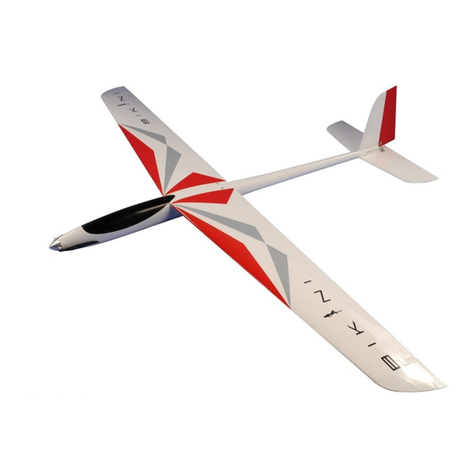
Envergure/wingspan: 2,01m
Longueur/length: 1,55m
Poids/TO weight: 5,8kg
Surface/wing area: 61dm2
Profil/airfoil: NACA 2414
Equipements recommandés/Recommended equipments:
Moteur/motor: XPower EP 35cc
Contrôleur/ESC: HW FLYFUN V5 HV130A
Accu/battery pack: 2x LiPo Hot Lips 18,5V 5000mAh 5S1P XT60
Hélice/prop: APC Electric 20x10”
Cône/spinner: INOVA Ø75mm
Radio/RC set: Emetteur/Transmitter: 10 voies/ 10-channel mini
Récepteur/receiver: JETI DUPLEX R10 EX
Ailerons: 2 servos TOPMODEL S5514
Profondeur/Elevator: 1 servo TOPMODEL S5514
Direction/Rudder: 2 micro servos TOPMODEL MS2810MG
Volets/Flaps: 2 servos TOPMODEL S5514
Crochet RMQ/Tow Hook: 1 servo TOPMODEL S5514
Dirig. roulette queue/TW steering: 1 servo TOPMODEL S5514
Easy
to
build
EP Tow Plane
Remorqueur Electrique
ADV
Pour modélistes
ayant un bon niveau
For advanced
modellers
Kit
découpé laser
Laser Cut
Kit
KIT
Propulsion
Electrique
Electric
Powered
2
MERCI
d’avoir choisi le remorqueur électrique à construire E-TRACTOR PRECISION PRODUCTS!
Nous avons fait un grand effort en dessinant et construisant cet avion pour qu’il soit le meilleur modèle que vous ayez jamais construit et fait
voler.
Nous vous fournissons un kit à construire avec la plus haute qualité et les meilleures performances possibles.
Nous vous souhaitons un grand succès en construisant et en faisant évoluer votre nouveau
E-TRACTOR PRECISION PRODUCTS
Pour concevoir ce modèle, nous nous sommes aidé de notre très grande expérience accumulée avec le BIDULE qui, il faut bien le dire, est
devenu la référence en matière de remorquage dans le monde entier. Ainsi, nous avons repris la même conception aérodynamique et nous
avons adapté la cellule pour qu’elle accepte parfaitement la propulsion électrique. Tout cela donne un avion de 2m d’envergure parfaitement
dimensionné et motorisé pour assurer le remorquage facile de planeurs jusqu’à 10kg. Vous allez apprécier sa mise en œuvre rapide et sa
facilité d’utilisation et les riverains vont apprécier le silence!
IMPORTANT: Merci de bien vouloir lire et étudier cette notice de montage avant de commencer l’assemblage. Faire l’inventaire des pièces à
l’aide de la nomenclature pour contrôler qu’il n’y a pas de manquant ou d’imperfection.
Merci de contacter immédiatement TOPMODEL si vous constatez une pièce manquante ou une pièce endommagée.
GARANTIE: Il est important de notifier à TOPMODEL tous dommages ou problèmes avec ce modèle dans les 14 jours suivant la réception du
kit pour bénéficier de la garantie. En cas de retour du modèle, le client est responsable du transport et le port retour est à sa charge. En cas
de défaut, la pièce sera échangée ou remplacée une fois que celle-ci sera réceptionnée par TOPMODEL pour expertise (transport à la charge
du propriétaire). En cas de problème, n’hésitez pas à contacter TOPMODEL.
TOPMODEL ne peut pas contrôler la dextérité du modéliste et ne peut pas influencer le constructeur durant l’assemblage ou l’utilisation de ce
modèle radio-commandé. Aussi, nous ne pouvons, en aucun cas, être tenus responsables des dégâts matériels, accidents corporels ou décès
pouvant être causés par ce modèle réduit.
L’acheteur/utilisateur accepte toutes les responsabilités en cas de problèmes structurels ou mécaniques.
H THANK YOU for your purchase of the laser kit of the Electric Powered Tow Plane
E-TRACTOR PRECISION PRODUCTS!
We made a main effort while drawing and building this plane so that it is the best model you ever built and fly.
We provide you a kit with the highest quality and the best possible performances.
We wish you a great success while assembling and flying your new
E-TRACTOR PRECISION PRODUCTS.
To design this model, we have used our vast experience accumulated with the BIDULE which, it must be said, has become the benchmark
for towing sailplanes around the world. Thus, we have taken the same aerodynamic design and we adapted the airframe to perfectly fit the
electric power. All this gives a plane of 2m wingspan perfectly sized and powered to ensure the easy towing of gliders up to 10kg. You will
appreciate its rapid implementation and ease of use and local residents around teh airfield will appreciate the silence!
IMPORTANT: Please take a few moments to read this instruction manual before beginning assembly. Do an inventory of the parts using the
parts list, to control that there is no lack or imperfection.
Thank you to contact TOPMODEL immediately, if you note a missing part or a damaged part.
WARRANTY: It is important to notify to TOPMODEL all damages or problems with this model within 14 days following the reception of the kit to
be able to benefit the warranty. In the event of return of the model, the customer is responsible for transport and return shipping cost is at his
expenses. In the event of defect, the part will be exchanged or replaced once this one will be delivered to TOPMODEL for expertise (transport
on your cost). In the event of problem, do not hesitate to contact TOPMODEL.
TOPMODEL cannot control the dexterity of the modeler and cannot influence the builder during the assembly or the use of this
radiocontrolled model, thus TOPMODEL will in no way accept or assume responsability or liability for damages resulting from the use of this
user assembled product.
The purchaser/user accepts all the responsabilities in the event of structural or mechanical problems.
3
POUR ASSEMBLER CE KIT
Pour assembler ce kit, vous aurez besoin des produits énumérés ci-dessous:
n COLLES: Cyano fluide, mi-fluide et épaisse, activateur cyano, colle époxy bi-composants 30mn et 5mn, colle à bois (blanche), micro ballons, floc
de coton.
n OUTILS: Plan de travail parfaitement plan, un étau, scie, couteau de modéliste, tournevis plat et cruciforme (petit et moyen), clés allen, pince à
bec fin, pince coupante, ciseaux, ruban adhésif, ruban adhésif de masquage, perçeuse (foret tous diamètres), Super Z bender (pince à baïonnette),
papier verre, cales à poncer, rabot, épingles modélisme, gros élastiques, réglet métal, équerre, feutre, pinces hobby, lest (vieilles revues par ex.), de la
cordelette, alcool à brûler, fer à solar, décapeur thermique, chiffon, etc.
Principe général de construction des kits PRECISION PRODUCTS TOPMODEL découpés laser
Grâce à la précision et à la finesse de découpe de la machine CNC laser, tous les assemblages sont conçus avec des “tenons-
mortaises” qui permettent d’assembler le kit en l’air à blanc (plus besoin de construire sur le plan comme jadis). A ce stade il est
possible de regarder en détail, tous les ajustements, la rectitude, la symétrie et de rectifier jusqu’à obtenir un assemblage parfait
à blanc. Immobiliser à l’aide de ruban adhésif papier si nécessaire. A ce moment là et à ce moment là seulement, il est possible de
procéder au collage. Ne surtout pas tout redémonter mais sans rien toucher à votre assemblage, faire pénétrer la colle cyano fluide
par infiltration dans les joints. Commencer par coller par points, puis, tout en contrôlant que rien ne bouge et que la symétrie et la
rectitude sont toujours parfaites, parfaire tous les collages.
RAPPEL
Nous prenons grand soin à fournir la meilleure qualité possible.
Toutefois, nous vous rappelons que ce ne sont pas des modèles prêts à voler et que la part du travail restante vous incombant est très importante pour
rendre le modèle apte au vol. Pour cette raison, nous vous demandons de bien vouloir contrôler tous les collages et assemblages.
Sécurité d’abord!
Nous vous remercions pour votre attention lors de l’assemblage de nos kits, et vous souhaitons de bons et nombreux vols!
TOPMODEL SAS
H TO ASSEMBLE THIS KIT
To assemble this kit, you’ll need the items listed below:
n ADHESIVE: CA thin, medium and thick, CA kicker, epoxy 30’ and 5’ adhesives, wood glue, microballons, cotton flocks.
n TOOLS: Perfectly flat working board, a vice, saw, knife (X-acto), Phillips and slotted screwdrivers (small and medium), allen wrenches, needle tip pli-
ers, pliers, scissors, adhesive tape, masking tape, drill (bits all-size set), Z-bender, sanding paper, sanding blocks, balsa plane, modeling pins, big rubber
bands, steel rule, square, ball point pen, hobby clamps, ballast (used magazines for ex.), strings, alcohol, solar iron, heat gun, piece of cloth or rags, etc.
General principles of construction of PRECISION PRODUCTS TOPMODEL Laser-Cut kits
Thanks to the precision and finesse of the laser cutting CNC machine, all assemblies are designed with locking keys which allow
to assemble the kit “in the air” without gluing (no need to build on the plan like before). At this stage it is possible to look in
detail, all adjustments, straightness, symmetry and to adjust until a perfect blend is found out. Immobilize the whole assembly us-
ing paper tape if necessary. At that time and at that time only, it is possible to carry out bonding. Do not disassemble but without
touching anything, apply thin CA into the joints by infiltration. Start gluing by dots, then, while checking that nothing moves and
the symmetry and straightness are always perfect, assure all collages.
REMINDER
We take great care to delivering the best possible quality.
We kindly remind you that these models are not ready to fly and that the remaining work is an important part to get the model flying. For this reason,
please, check all glue joints and assemblies.
Safety first!
We thank you for your attention during the assembly of our kits, and wish you good and numerous flights!
TOPMODEL SAS
4
CONTENU DU KIT/ KIT CONTENT
CTP PEUPLIER 3mm / POPLAR PLYWOOD 3mm
(A) 3.0x1000x100mm................................................................ 1
(B) 3.0x630x150mm .................................................................. 2
(C) 3.0x1000x150mm................................................................ 1
(D) 3.0x1000x150mm................................................................ 1
(E) 3.0x1000x150mm................................................................ 1
(F) 3.0x1000x155mm................................................................ 1
(G) 3.0x1000x150mm................................................................ 1
(H) 3.0x750x150mm .................................................................. 1
A
B
C
D
E
F
G
H
5
CONTENU DU KIT/ KIT CONTENT
BALSA 3mm
(I) 3.0x1000x100mm................................................................ 1
(J) 3.0x1000x100mm................................................................ 2
(K) 3.0x320x100mm .................................................................. 2
BALSA 5mm
(L) 5.0x1000x100mm................................................................ 1
(M) 5.0x1000x100mm................................................................ 1
(N) 5.0x1000x100mm................................................................ 1
BALSA 2mm
(O) 2.0x1000x100mm................................................................ 2
(P) 2.0x1000x100mm................................................................ 2
(Q) 2.0x1000x100mm................................................................ 2
(R) 2.0x1000x100mm................................................................ 2
(S) 2.0x1000x100mm................................................................ 2
(T) 2.0x780x100mm .................................................................. 2
I
J
K
L
M
N
O
P
Q
R
S
T
6
CONTENU DU KIT/ KIT CONTENT
BALSA 1.5mm
(U) 1.5x1000x100mm................................................................ 1
(V) 1.5x1000x100mm................................................................ 1
(W) 1.5x1000x100mm................................................................ 1
(X) 1.5x500x100mm .................................................................. 1
CTP BOULEAU 5mm / BIRCH PLYWOOD 5mm
(Y) 5.0x600x150mm .................................................................. 1
CTP BOULEAU 3mm / BIRCH PLYWOOD 3mm
(Z) 3.0x200x60mm .................................................................... 1
BAGUETTES BOIS DUR/HW STRIPS
(MS) 5x10x1000mm ..................................................................... 4
BAGUETTES BALSA/BALSA STRIPS
(CS) 10x10x1000mm ................................................................... 5
(FR) 8x8x1000mm........................................................................ 2
(LA) 5x10x1000mm ..................................................................... 1
(TE) 10x50x1000mm ................................................................... 1
(TE) 10x50x500mm ..................................................................... 1
TOURILLON HETRE/BEECH DOWEL
(IP) Ø6x330mm ........................................................................... 1
U
W
V
X
MS
CS
FR
LA
TE
TE IP
Y
Z
7
CONTENU DU KIT/ KIT CONTENT
A- Sachet «Fuselage»
Vis Chc tête bombée M4x16.......................................3pcs
Ecrou-griffe M4...........................................................3pcs
Axe de roue Ø5x51mm...............................................1paire
Bague arrêt de roue Ø5mm.......................................2pcs
Vrac
Train fibre 375x180mm..............................................1pc
Roue Ø127x46mm .....................................................1paire
Roulette de queue +accessoires ...............................1set
B- Sachet «Ailes»
Guignol volet et aileron...............................................4sets
Charnière Ø3x48mm ..................................................16pcs
Vis fixation aile nylon M4x14......................................2pcs
Ecrou-griffe M4...........................................................2pcs
C- Sachet «Empennages»
Guignol profondeur.....................................................1set
Guignol dérive.............................................................2sets
Vis nylon fixation stab M5x30mm...............................2pcs
Ecrou-griffe M5...........................................................2pcs
Charnière Ø3x48mm ..................................................11pcs
Vis Chc tête bombée M3x16mm.................................6pcs
Ecrou-griffe M3...........................................................4pcs
Ecrou nylstop M3........................................................2pcs
Vis Chc auto-taraudante 2,5x16mm...........................2pcs
Tube alu Ø6x200mm ..................................................2pcs
Cache servo 90x75mm ..............................................1paire
D- Sachet «Verrière»
Verrou verrière...........................................................1pc
Verrière Fibre de verre moulée..................................1pc
Vrac - Autres accessoires
Clé d’aile carbone Ø20x600mm + fourreau..............1set
Crochet de remorquage + visserie de fixation ..........1set
A- «Fuselage» bag
M4x16 button socket screw .......................................3pcs
M4 tiger nut................................................................3pcs
Ø5x51mm wheel axle .................................................1pair
Ø5mm wheel stopper .................................................2pcs
Bulk
Fiberglass landing gear 375x180mm ........................1pc
Ø127x46mm wheel ....................................................1pair
Tailwheel +hardware..................................................1set
B- «Wings» bag
Flaps and ailerons control horn .................................4sets
Ø3x48mm hinge point................................................16pcs
M4x14 wing bolt.........................................................2pcs
M4 tiger nut................................................................2pcs
C- «Empennages» bag
Elevator control horn .................................................1set
Rudder control horn ...................................................2sets
M5x30mm stab bolt....................................................2pcs
M5 tiger nut................................................................2pcs
Ø3x48mm hinge point................................................11pcs
M3x16mm button socket screw .................................6pcs
M3 tiger nut................................................................4pcs
M3 lock nut.................................................................2pcs
2.5x16mm self-tapping screw....................................2pcs
Ø6x200mm aluminium tube .......................................2pcs
90x75mm servo cover ...............................................1pair
D- «Canopy» bag
Canopy latch ...............................................................1pc
Fiberglass molded canopy..........................................1pc
Bulk - Others accessories:
Ø20x600mm carbon wing joiner + pocket................1set
Remote Tow Hook + attachment screws ...................1set
A B C D
8
Réunir l’ensemble des pièces: le sachet accessoires
«Ailes» + la clé d’aile, les planches CTP (A) et (B), les
planches balsa (L) à (T) ainsi que les baguettes pin
5x10 (MS) et le tourillon hêtre 6mm (IP).
H Gather all the parts: the accessories bag «Wings» +
the wing joiner, the ply boards (A) and (B), the balsa
boards (L) to (T) as well as the 5x10 pine strips (MS)
and the 6mm beech dowel (IP).
Détacher soigneusement toutes les pièces constituant
l’ossature de l’aile, conserver toutefois les évidements
contenant un numéro.
H Carefully detach all the parts constituting the frame
of the wing, however keep the recesses containing a
number.
Coller à la colle époxy les nervures W2 sur les ner-
vures W1. Pensez à travailler de façon symétrique an
de réaliser une aile droite et une aile gauche!
H Glue the ribs W2 on the ribs W1 with epoxy glue.
Think of working symmetrically to achieve a right
wing and a left wing!
Insérer toutes les nervures dans l’ordre sur le longe-
ron L2, puis les supports servo SVA et SVB. Attention
au sens, l’emplacement servo côté emplanture, et la
partie la plus large vers l’avant!
Voir photos suivantes...
H Insert all the ribs by number on the L2 spar, then
the SVA and SVB servo brackets. Beware of the mea-
ning, servo hole on the wing root side, and the widest
part facing forward!
Have a look to the following photos...
AILES/ WINGS
W1 W2
W3
W4
L2
9
AILES/ WINGS
... ensuite la butée de la clé d’aile BC, les pièces L2b,
L1 et L3 et pour nir le longeron supérieur en pin
5x10mm (MS). Maintenir le tout avec quelques
morceaux de scotch, contrôler la géométrie à l’aide
d’équerres, comme montré.
H ... then the end stop BC for the wing joiner, L2b, L1
and L3 parts and nally the main upper spar 5x10mm
(MS). Hold everything with a few adhesive tape pieces,
control the geometry using squares as shown.
Une fois s’être bien assuré que tout est à sa place, poin-
ter à la cyano mi-uide en commençant par les 4 coins
de l’aile, puis bord d’attaque et de fuite ensuite longe-
ron. Retourner l’aile, insérer le longeron inférieur pin
5x10mm (MS).
H Once you have made sure that everything is in place,
point glue to the medium cyano starting at the four
corners of the wing, then leading edge, trailing edge
and then main spar. Flip the wing, insert the lower
spar 5x10mm pine (MS).
Repositionner votre aile, naliser les collages tout en
contrôlant la géométrie.
!!! Attention aussi à la nervure W1/W2 qui doit par-
faitement épouser les longerons pour respecter le
dièdre!
H Reposition your wing, perform and perfect all the
gluings while controlling the main geometry.
!!! Attention: the rib W1 / W2 must perfectly marry
the side of the spar to respect the dihedral angle!
Découper dans le fourreau de la clé d’aile 2 longueurs
de 235mm (le reste sera pour le fuselage).
H Cut the pocket of the wing joiner in 2 lengths of
235mm (the rest will be for the fuselage).
SVA
!!!
L3
BC L1 (MS)L2b
SVB
235 235
10
AILES/ WINGS
Dépolir les fourreaux (235mm) au papier de verre,
puis les insérer dans les ailes jusqu’à la butée BC et
les pointer à la cyano ainsi que les renforts I, II et III.
H Scrape the wing joiner pockets (235mm) with sand-
paper, then insert them into the wings up to end stop
BC and glue point them with cyano as well as reinfor-
cements I, II and III.
Renforcer tous les collages à la colle époxy chargée de
micro-ballon et de oc de coton.
Même opération à l’intrados avec les renforts IV, V et
VI.
H Reinforce all the gluings with epoxy glue loaded
with micro-balloon and cotton oc.
Same operation on the bottom of the wing with rein-
forcements parts IV, V and VI.
Ajuster le bord d’attaque L1 et bord de fuite L3 au pro-
l de l’aile par rabotage et ponçage. Il est recommandé
de protéger les nervures avec du scotch d’emballage.
H Shape the L1 leading edge and L3 trailing edge to
the wing airfoil by planing and sanding. It is recom-
mended to protect the ribs with packing tape.
Assembler au ruban adhésif de masquage puis coller
les pièces CA constituant le corage d’extrados entre-
elles (attention, 1 côté Droit et 1 côté Gauche!) puis
poncer nement la face extérieure.
Repérer et mettre de coté les corages d’ailerons et
volets.
H Assemble with masking tape and glue together the
CA parts forming the top sheeting (be careful, 1 Right
side and 1 Left side!), then sand the outer face nely.
Identify and set aside ap and aileron top sheetings.
BC
I
IV
IV
V
V
VI
VI
II III
L3
L1
Volet/Flap Right UP Aileron Right UP
CA Right UP
CA Left UP
Dessus/Top
Dessous/Bottom
11
AILES/ WINGS
Encoller l’ensemble de la structure de l’aile et y posi-
tionner le corage Extrados CA à l’aide des ergots pré-
sents sur L2.
H Put glue on the entire wing upper structure and
then locate the CA top sheeting using the pins on L2.
Mettre sous presse; des revues sont parfaites pour
épouser le prol. Veiller à ce que le corage soit en
contact avec toute la structure. Maintenir à l’aide de
scotch papier si nécessaire.
H Put under load; magazines are perfect to t the pro-
le. Ensure that the sheeting is in contact with the en-
tire structure. Keep using masking tape if necessary.
Une fois bien sec, retourner l’aile et détacher les ta-
lons des nervures extérieures et aussi ceux des bords
d’attaque L1 et de fuite L3.
Coller les 8 renforts R1 aux endroits des charnières
(trous des charnières déja percés dans le BdF).
H Once dry, ip the wing and remove the building
wedges of the outer ribs and also those of the leading
edges L1 and trailing edge L3.
Glue the 8 reinforcements R1 at the location the
hinges (hinges point holes are already drilled in the
trailing edge).
Ajuster L1, L3 et les renforts R1 au prol de l’aile, pro-
téger les nervures avec du scotch d’emballage.
Pensez à coller l’écrou-grie M4 de maintien des ailes
(trou sur la nervure d’emplanture W1/W2 en arrière
de la clé d’aile).
H Sand shape L1, L3 and R1 to the wing prole, pro-
tect the ribs with packing tape.
Remember to glue the M4 tigernut (hole in the root
rib W1/W2 behind the wing joiner).
Dessus/Top
Dessus/Top
Dessous/Bottom
Dessous/Bottom
R1
R1
L1
L3
L3
L1
12
AILES/ WINGS
De même que pour l’extrados, assembler et coller les
corages d’intrados CAi (attention, 1 Droit 1 Gauche)
et poncer nement le coté extérieur. Repérer et mettre
de coté les corages d’ailerons et volets.
H Assemble with masking tape and glue together the
CAi parts forming the bootom sheeting (be careful, 1
Right side and 1 Left side!), then sand the outer face
nely.
Identify and set aside ap and aileron bottom shee-
tings.
Utiliser le bord de fuite balsa 10x50 TE du kit pour
caler votre aile sur le chantier. Encoller la structure.
Positionner le corage CAi au ras de L3….
H Put the fuselage upside down. Glue with epoxy adhe-
sive RT landing gear reinforcements inside of each
fuse side then the F4R parts that are inserted in the
F4 former. Keep in place using clamps.
Then glue the ST gear plate. The holes for the gear
legs must coincide with those of RT.
Servez vous des trous du logement des servos pour
centrer le corage CAi.
Immobiliser et mettre sous presse.
H Use holes in the servo housing to center the CAi
sheeting.
Immobilize and go to press.
Poncer les corages intrados Cai et extrados CA à
eur de L1 et coller le bord d’attaque (pièce BA). Le
poncer exactement à la forme du prol.
Finir l’aile par un ponçage général soigné.
H Sand the Cai bottom sheeting and AC top sheeting
ush with L1, then glue the leading edge (part BA).
Sand it exactly to the shape of the airfoil.
Finish the wing with a careful and ne general san-
ding.
Volet/Flap Right BottomAileron Right Bottom
Au raz!
Flush
Centrez!
Center!
CAi Right Bottom
CAi Left Bottom
Dessous/BottomDessous/Bottom
TE
CAi
CAi
13
AILES/ WINGS
Découper le tourillon de hêtre Ø6mm IP en 4 mor-
ceaux d’environ 75mm. Enler puis coller dans les
nervures W1/W2 et W3.
H Cut the Ø6mm beech dowel IP into 4 pieces of about
75mm long. Insert and glue into ribs W1 / W2 and W3.
Rassembler les pièces constituant les ailerons et les
volets de courbure, corages intrados et extrados
(réservées à l’étape précédente), nervures NA (toutes
identiques) et bords d’attaque A1 et A2).
H Gather the parts constituting the ailerons and cam-
ber aps, top and bottom sheetings (reserved at the
previous step), ribs NA (all identical) and leading
edges A1 and A2).
Positionner les nervures A2 dans leur encoche sur les
corages d’intrados, puis le bord d’attaque A2.
Attention au sens, voir photo suivante.
H Position the ribs A2 in their notch on the bottom
sheeting, then the leading edge A2.
Beware! Respect the direction of the ribs, see next
photo.
BA
IP
IP
IP
NA
NA
NA
NA
A2
A2
A2A2
A1
A1 A1
A1
W1
75
Volets/Flaps Ailerons
A2
A2
A2
NA
Corage intrados
Bottom Sheeting
14
AILES/ WINGS
La position des nervures doit être en concordance
avec celle de l’aile!
Maintenant, vous pouvez coller.
H All rhe ribs of ap and aileron must face to the ribs
of the wing!
Now, you can glue.
Coller les renforts R2 pour les guignols de volet et d’ai-
leron comme montré sur la photo.
NB: Il s’agit là, de l’aile droite !
Poncer à eur, au ras des nervures, A2 et le renfort R2
et coller ensuite le corage d’extrados.
H Glue the R2 reinforcements for the ap and aileron
control horns as shown at the photo.
NB: This is the right hand wing!
Sand ush with the ribs, A2 and reinforcement R2
and then glue the top sheeting.
Coller ensuite le bord d’attaque A1, vérier avant
que les emplacements des encoches pour les char-
nières correspondent avec ceux de l’aile (dans le cas
contraire, ce n’est pas le bon!).
H Then glue the leading edge A1, check before the loca-
tions of the notches for the hinges point correspond
with those of the wing (otherwise, it is not the good
one!).
Finir les gouvernes par un ponçage général pour ajus-
ter les corages.
Poncer le bord d’attaque de l’aileron en forme de
double biseau.
Celui du volet restant droit (voir ci-contre).
H Sand nish the control surfaces to adjust the shee-
tings.
Bevel sand the leading edge of the aileron in double
bevel.
Leading edge of the ap remains at (see drawings).
Volets/Flaps
Ailerons
A2
R2
R2
Volet/Flap
Aileron
A1
A1
15
AILES/ WINGS
Percer à Ø3mm sur les emplacements des charnières
bâton.
Percer droit pour les charnières d’ailerons.
Celles des volets étant insérées à 45° de part et d’autre,
l’articulation venant aeurer le corage d’intrados.
H Drill to Ø3mm on the hinges point locations.
Drill straight for the ailerons hinges.
Those for aps being inserted at 45° on both sides, the
joint coming ush with the bottom sheeting.
Les gouvernes étant posées, passer un coup de cale à
poncer au bord de fuite pour aligner l’ensemble.
H The control surfaces being completed, align the trai-
ling edges with a long sanding block.
Procéder de la même manière pour construire l’aile
gauche.
H Proceed the same way to build the left hand side
wing.
Volet/Flap
90°
Dessous/Bottom
16
EMPENNAGES
Réunir l’ensemble des pièces : sachet accessoires «Em-
pennages», corages U à X, les pièces RD1, RD2, RD3
et RD4 ainsi que RS1, RS2 et RS3, nervures N1, N2
et N3, supports servo SVD, longerons S1, S2 et S3,
2 baguettes balsa 8x8 (FR) et 1 baguette balsa 5x10
(MS), 1,50m bord de fuite balsa 10x50 (TE).
H Gather all the parts together: bag «Empennages» ,
sheetings U to X, parts RD1, RD2, RD3 and RD4 as
well as RS1, RS2 and RS3, ribs N1, N2 and N3, servo
frames SVD, spars S1, S2 and S3, 2 balsa strips 8x8
(FR) and 1 balsa strip 5x10 (MS), 1.50m balsa trai-
ling edge 10x50 (TE).
Coller les écrous gries M3 sur les renforts RS3 puis
sur les nervures N3. Ajuster la largeur les écrou-
gries en fonction de la nervure (pince coupante ou
mieux, disque à tronçonner).
Attention, 1 nervure droite et 1 nervure gauche!
H Glue the M3 tiger nuts on the RS3 parts then on to
the N3 ribs. Adjust the width of the tiger nut accor-
ding to the rib shape (do it with cutting pliers or bet-
ter, cutting disc).
Be careful, 1 right rib and 1 left rib!
Enler les nervures N1, N2, N3 sur les longerons S1,
S2 et S3, insérer les renforts RS1 et RS2.
Vérier la géométrie et coller.
H Slide the ribs N1, N2, N3 in the spars S1, S2 and S3,
insert the reinforcements RS1 and RS2.
Check the geometry and glue.
Dans des chutes de balsa, réaliser 2 cales destinées à
remplir l’espace entre RS1 et le corage supérieur…
H With balsa scraps, make 2 wedges to ll the space
between RS1 and the upper sheeting ...
RS3
N3
N3 N1N1N2 N2 N3
S1
RS1
RS1RS2 RS2
S2
S3
RS3
Dessus/Top
Dessus/Top
17
EMPENNAGES
... puis les coller sur les renforts RS1.
H ... then glue them on the RS1 reinforcements.!
Ajuster au prol du stab les longerons et les cales de
balsa. Protéger les nervures à l’aide de scotch d’em-
ballage.
H Sand to the stab airfoil the spars and the balsa
wedges. Protect the ribs with packing tape.
Assembler et coller les 2 parties du corage d’extra-
dos S.
Poncer nement la surface extérieure.
H Assemble and glue together the two parts consti-
tuing upper sheeting S.
Sand the outer surface nely.
Encoller la structure du stab.
Se servir des trous de xation du stab pour aligner le
corage et mettre sous presse.
H Apply glue to the whole structure of the stab.
Use the stab attachment holes to align the sheeting
and press.
Dessus/Top
Dessus/Top
Dessus/Top
Poncer
Sand
Poncer
Sand
S
S
18
EMPENNAGES
Une fois bien sec, retourner le stab et détacher les ta-
lons des nervures ainsi que du bord d’attaque et de
fuite.
H Once fully dry, ip the stab over and cut remove the
building wedges from the ribs as well as from leading
edge and trailing edge.
Coller ensuite les supports servo SVD.
Attention au sens, la partie la plus large vers l’avant.
H Then glue the SVD servo frames.
Beware of the direction! the widest part forward.
Découper dans des chutes de balsa, des renforts aux
endroits des 5 charnières (il y a des trous pré-percés
dans S3).
H Cut into balsa scraps, reinforcements at the 5 hinges
point (there are pre-drilled holes in S3).
Ne pas oublier de passer une cordeletet à travers le
stab pour pouvoir ensuite tirer les rallonges de servos.
Comme précédemment, ajuster les longerons au prol
en les poncant.
Caler le stab sur le chantier à l’aide du BdF 10x50.
Assembler le corage Si et corer l’intrados.
H Do not forget to route a wire through the stab so you
can pull the servos extensions.
As before, sand adjust the spars to the shape of the
airfoil of the stab.
Lay down at and level the stab on working bench
with the help of the 10x50 TE strip.
Assemble the bottom sheeting Si and glue it.
Dessous/Bottom
Dessous/Bottom
Chutes balsa/Balsa scraps
Avant
Front
SVD
19
EMPENNAGES
Finir le stab par un ponçage général pour ajuster les
corages à la structure.
Coller le bord d’attaque 5x10 LA sur S1 et poncer au
prol.
Découper le bord de fuite 10x50 TE à la longueur
du stab moins 5mm et en biseau aux extrémités sur
30mm.
H Finish the stab with a general sanding to adjust the
sheetings to the structure.
Glue the 5x10 LA leading edge to S1 and sand to the
airfoil shape.
Cut the trailing edge 10x50 TE to the stab length mi-
nus 5mm and bevel at both ends as shown.
Poncer le bord d’attaque du volet de profondeur en
forme de double biseau. Le centrer par rapport au stab
et repérer la position des charnières. Percer à Ø3mm
et installer les charnières sans les coller.
H Sand the leading edge of the elevator into a double
bevel. Center it in relation to the stab and locate the
position of the hinges point. Drill to Ø3mm and install
the hinges point without glueing them.
Assembler et coller les éléments des corages de dé-
rives D.
Poncer nement les extérieurs.
H Assemble and glue the parts D constituing the shee-
tings of the vertical empennages.
Sand the outer surfaces nely.
Contre-coller les pièces RD1 avec RD2 et RD3 avec
RD4.
Attention, un coté droit et un coté gauche!
H Counter-glue pieces RD1 with RD2 and RD3 with
RD4.
Attention, you should get a right side and a left side!
30 LA
DD
D
RD4
RD3
D
TE
Profondeur
Elevator
Charnières
Hinges
20
EMPENNAGES
Coller l’ensemble RD1/2 sur le corage, de préférence
coté CTP, se servir des vis et des trous de xation des
dérives pour positionner la pièce.
H Glue the RD1/2 assembly to the sheeting, preferably
on the ply side, using the screws and the attachment
holes of the vertical empenange to locate the part.
Coller la baguette balsa 8x8 (FR) sur le pourtour du
corage comme montré.
H Glue the 8x8 balsa strip (FR) around the edge of the
sheeting as shown.
A l’aide d’une vis, positionner puis coller le renfort
RD3/4 sur le corage.
Découper et coller la baguette 8x8 (FR) pour former
la nervure centrale et marginale.
Découper et coller 3 bouts de baguettes 8x8 répartis
équitablement pour renforcer les emplacements des 3
charnières.
H Using a screw, position and then glue the RD3/4
reinforcement to the sheeting.
Cut and glue the 8x8 (FR) strip to form the central
and marginal rib.
Cut and glue 3 pieces of 8x8 strip distributed evenly
to reinforce the locations of the 3 hinges point.
Repérer la dérive droite et la gauche (RD2 en CTP
vers le coté extérieur de la dérive).
Surfacer l’ensemble puis corer.
Découper les volets de direction dans (TE), poncer le
bord d’attaque en forme de double biseau.
Repérer la position des 3 charnières, percer à Ø3mm
et installer sans coller.
H Locate the right and left n (RD2 made in ply facing
towards the outer side of the n).
Sand at the whole assemble and then glue the sheeting.
Cut out the rudders in (TE), sand the leading edge into
a double bevel shape.
Mark the lacation of the 3 hinges, drill to Ø3mm and
install them without glueing.
FR
RD3/4
FR
RD1
RD1
RD1
RD2
FR
FR
FR
TE
FR
D
Renforts charnières
Hinges reinforcement
Dérive gauche
Left n
Dérive gauche
Left n
Dérive gauche
Left n
Dérive droite
Right n
Dérive droite
Right n
Dérive droite
Right n

Other Topmodel Toy manuals

Topmodel Saturn Evolution Biplan de competition... Operation and maintenance manual

Topmodel

Topmodel Saturn Evolution Biplan de competition... Operation and maintenance manual

Topmodel XPOWER DISCOVERY User manual

Topmodel

Topmodel XPOWER DISCOVERY User manual

Topmodel Discus 2c User manual

Topmodel

Topmodel Discus 2c User manual

Topmodel Grafas User manual

Topmodel

Topmodel Grafas User manual

Topmodel Joy2Fly User manual

Topmodel

Topmodel Joy2Fly User manual

Topmodel XPower mercury EVOLUTION User manual

Topmodel

Topmodel XPower mercury EVOLUTION User manual

Topmodel ExtraCT ECOTOP User manual

Topmodel

Topmodel ExtraCT ECOTOP User manual

Topmodel ECOTOP CHARLIE WHISKY User manual

Topmodel

Topmodel ECOTOP CHARLIE WHISKY User manual

Topmodel viking 02007 User manual

Topmodel

Topmodel viking 02007 User manual

Topmodel BIDULE 170 ECOTOP User manual

Topmodel

Topmodel BIDULE 170 ECOTOP User manual

Topmodel Ecotop Scale Series User manual

Topmodel

Topmodel Ecotop Scale Series User manual

Topmodel Scale Series User manual

Topmodel

Topmodel Scale Series User manual

Topmodel XPower Krasivo 2 User manual

Topmodel

Topmodel XPower Krasivo 2 User manual

Topmodel Pegasus 2E F5J/ALES User manual

Topmodel

Topmodel Pegasus 2E F5J/ALES User manual

Topmodel ECOTOP MAKSIM User manual

Topmodel

Topmodel ECOTOP MAKSIM User manual

Topmodel Maracana User manual

Topmodel

Topmodel Maracana User manual

Topmodel Precision Products micro Bullit User manual

Topmodel

Topmodel Precision Products micro Bullit User manual

Topmodel PILATUS B4 User manual

Topmodel

Topmodel PILATUS B4 User manual

Topmodel SKY WING SLICK 360 User manual

Topmodel

Topmodel SKY WING SLICK 360 User manual

Topmodel IPANEMA II XPower User manual

Topmodel

Topmodel IPANEMA II XPower User manual

Topmodel Condor User manual

Topmodel

Topmodel Condor User manual

Topmodel F3K FLITZ 2 User manual

Topmodel

Topmodel F3K FLITZ 2 User manual

Topmodel Baia User manual

Topmodel

Topmodel Baia User manual

Topmodel Ecotop Waka User manual

Topmodel

Topmodel Ecotop Waka User manual

Popular Toy manuals by other brands

Eduard P-51B/C Assembly instructions

Eduard

Eduard P-51B/C Assembly instructions

Faller 293027 manual

Faller

Faller 293027 manual

Star Wars BOOM BOOM BALLOON instructions

Star Wars

Star Wars BOOM BOOM BALLOON instructions

MTHTrains RAILKING GS-4 operating instructions

MTHTrains

MTHTrains RAILKING GS-4 operating instructions

Swalkertech S1 user manual

Swalkertech

Swalkertech S1 user manual

LeapFrog On-the-Go Story Pal instruction manual

LeapFrog

LeapFrog On-the-Go Story Pal instruction manual

MCD Racing RR5 Competition instruction manual

MCD Racing

MCD Racing RR5 Competition instruction manual

War Wing Ultimate Combat Delta Assembly instructions

War Wing

War Wing Ultimate Combat Delta Assembly instructions

Fisher-Price RC Stunt Raceway 72911 instructions

Fisher-Price

Fisher-Price RC Stunt Raceway 72911 instructions

MTHTrains Rail King Trolley Car Set operating instructions

MTHTrains

MTHTrains Rail King Trolley Car Set operating instructions

marklin baureihe 144 instruction manual

marklin

marklin baureihe 144 instruction manual

Eduard Gloster Javelin FAW.9/9R undercarriage quick start guide

Eduard

Eduard Gloster Javelin FAW.9/9R undercarriage quick start guide

The Learning Journey Techno Gears Dizzy Droid 2.0 instruction manual

The Learning Journey

The Learning Journey Techno Gears Dizzy Droid 2.0 instruction manual

Modeltech 123600 Instructions for final assembly

Modeltech

Modeltech 123600 Instructions for final assembly

ACME Zoopa 350 manual

ACME

ACME Zoopa 350 manual

Eduard Crusader F-8E Assembly instructions

Eduard

Eduard Crusader F-8E Assembly instructions

Mega Bloks HALO CNG69 manual

Mega Bloks

Mega Bloks HALO CNG69 manual

Bowaters MODELS BME-009 instructions

Bowaters MODELS

Bowaters MODELS BME-009 instructions

manuals.online logo
manuals.online logoBrands
  • About & Mission
  • Contact us
  • Privacy Policy
  • Terms and Conditions

Copyright 2025 Manuals.Online. All Rights Reserved.