Torc SafeStop SS03TX04 User manual

, Version #
UNCLASSIFIED // FOR OFFICIAL USE ONLY Torc Proprietary
torc.ai 1
[SS-UM] SafeStop User
Manual
Date: 2023.08.24
Version: 2023.08.24.1
Submitted to:
Prepared by: TORC Robotics
405 Partnership Drive
Blacksburg, VA 24060
FOR OFFICIAL USE ONLY
DISTRIBUTION STATEMENT D. Distribution authorized to Department of Defense
(DoD) and U.S. DoD contractors only (Administrative and Operational Use, Export
Controlled; 01 October 2014). Other requests for this document shall be referred to
PdM ALUGS, Building 1414 West Perimeter Road, SFAE- CSS-FP-RA; MS 901,
Harrison Township MI 48045
WARNING – This document contains technical data whose export is restricted by the
Arms Export Control Act (Title 22, U.S.C., Sec 2751, et seq.) Violations of these export
laws are subject to severe criminal penalties. Disseminate in accordance with
provisions of DoD Directive 5230.25.
DESTRUCTION NOTICE: Destroy by any method that will prevent the disclosure of
contents or reconstruction of the document.
This document contains information that may be exempt from mandatory disclosure
under the Freedom of Information Act.

, Version #
405
Partnership
Drive.
Blacksburg
VA
24060
Ph:
800.530.9285
torc.ai
0

SafeStop®User Manual, Version 2.0
3
Table of Contents
1. Assignment of Liability.................................................................................................................. 5
2. Technical Support......................................................................................................................... 5
3. General Safety Information .......................................................................................................... 6
4. Package Contents ......................................................................................................................... 7
4.1 Included Items .......................................................................................................................7
4.2 Optional Accessories..............................................................................................................8
5. Product Overview........................................................................................................................ 10
6. Product Specifications................................................................................................................ 12
7. SafeStop® Transmitter ................................................................................................................ 14
7.1 Transmitter Switch Detail....................................................................................................15
7.2 Transmitter Power Receptacle............................................................................................15
7.3 Transmitter LED Indicator Detail.........................................................................................17
7.4 Transmitter Audible Alarm ..................................................................................................18
8. SafeStop® OEM Transmitter........................................................................................................ 19
8.1 OEM Transmitter User Interface Connector Detail.............................................................20
8.2 OEM Transmitter DIP Switch Detail.....................................................................................20
8.3 OEM Transmitter LED Detail ................................................................................................21
8.4 OEM Transmitter Serial Commands....................................................................................21
9. SafeStop® Receiver...................................................................................................................... 24
9.1 Receiver Bypass Button Detail ............................................................................................25
9.2 Receiver Power Receptacle Detail.......................................................................................27
9.3 Receiver Safety Receptacle Detail.......................................................................................28
9.4 Receiver Output Circuit Schematic .....................................................................................29
9.5 Receiver LED Indicator Detail ..............................................................................................30
10. TCP (Telnet) Communications.................................................................................................... 31
10.1 Telnet Testing ......................................................................................................................35
11. RS-232 Receiver Serial Communications ................................................................................... 37

SafeStop®User Manual, Version 2.0
Manual, Version 2.0
4
12. Web Configuration ...................................................................................................................... 38
12.1 System Status ......................................................................................................................38
12.2 System Configuration ..........................................................................................................39
12.3 External Watchdogs .............................................................................................................41
12.4 Network Settings .................................................................................................................42
12.5 Multipoint Transmitters.......................................................................................................43
12.6 Firmware Updates................................................................................................................46
13. Restore Network and System Defaults....................................................................................... 48
14. System Integration...................................................................................................................... 49
14.1 Charging the Transmitter Battery .......................................................................................49
14.2 Installing the Antennas........................................................................................................49
14.3 Installing the Receiver Cables into the Vehicle System......................................................50
14.4 System Wiring ......................................................................................................................50
14.5 SafeStop Vehicle Wiring.......................................................................................................50
14.6 Example External Button Wiring Schematics .....................................................................52
14.7 Verify Operation of the System............................................................................................52
14.8 Intended SafeStop® Transmitter Usage and Examples......................................................55
15. Physical Dimensions ................................................................................................................... 59
15.1 SafeStop® Transmitter Dimensions ....................................................................................59
15.2 Transmitter Mount Dimensions ..........................................................................................60
15.3 SafeStop® Receiver Dimensions..........................................................................................61
15.4 SafeStop® Receiver Mounting Template.............................................................................61
16. FCC Compliance .......................................................................................................................... 63
17. Limited Warranty......................................................................................................................... 63
18. Revision ....................................................................................................................................... 64

SafeStop®User Manual, Version 2.0
Manual, Version 2.0
5
1. Assignment of Liability
WARNING: DO NOT OPERATE UNTIL USER MANUAL IS REVIEWED AND UNDERSTOOD. PRODUCT
USE IS SUBJECT TO STRICT TERMS AND CONDITIONS. SEE TERMS AND CONDITIONS DOCUMENT
FOR ADDITIONAL USE RESTRICTIONS. OPERATING PRODUCT IN VIOLATION OF USER
RESTRICTIONS COULD RESULT IN PRODUCT MALFUNCTION, PROPERTY DAMAGE, AND PERSONAL
INJURY INCLUDING DEATH.
NOTICE: USER ASSUMES ALL RISKS ASSOCIATED WITH POSSESSION OR USE OF PRODUCT AND
RELATED SYSTEMS. USER AGREES TO INDEMNIFY, DEFEND AND HOLD HARMLESS TORC
ROBOTICS, INC (“TORC”) FROM ANY DAMAGES ARISING OUT OF POSSESSION OR USE OF
PRODUCT AND RELATED SYSTEMS. Torc IS NOT LIABLE FOR DAMAGES OF ANY KIND.
NOTICE: SEE TERMS AND CONDITIONS FOR ALL TERMS APPLICABLE TO USE OF THE PRODUCT OR
RELATED SOFTWARE.
2. Technical Support
For technical assistance and repairs, please use the following contact information:
Mailing Address Email and Phone Support
Torc Product Support
405 Partnership Drive
Blacksburg, VA 24060
support@torcrobotics.com
torc.ai
Phone: (800) 530-9285
Copyright © 2023 Torc Robotics, Inc. All Rights Reserved.
All information contained in this manual is believed to be accurate at the time of printing, however, Torc Robotics, Inc. reserves
the right to make modifications to the specifications and operation of this product without obligation to notify any person or
entity of such revision.

SafeStop®User Manual, Version 2.0
Manual, Version 2.0
6
3. General Safety Information
The following symbols are used throughout the user manual to indicate a particularly hazardous
condition.
WARNING: Indicates a hazardous condition that could result in serious injury or
loss of life if not performed properly.
CAUTION:Indicates a hazardous condition or procedure that could result in
damage to this product, or loss related to equipment malfunction.
NOTE:A note indicates information that may not be applicable regarding system
safety but needs to be known for best system performance.
Use Redundant Safety Measures
This product is not intended to be used as the only safety stop device. It is the user’s
responsibility to ensure that adequate and redundant safety measures are implemented.
Use Proper Supplied Accessories
To prevent damage to the product, use only the recommended accessories, including power
adapters, antennas, and cables.
Observe All Connector Ratings
To avoid shock hazard and/or damage to the product, do not exceed any voltage, current, or
environmental ratings on any of the connectors.
Do Not Charge Unattended
To avoid fire hazard and/or damage to the product, monitor the SafeStop® transmitter when
connected to an external power supply.
Do Not Operate with Suspected Failures
If you suspect damage to the product, contact Torc to have it inspected before further use.
Do Not Modify or Disassemble
To avoid shock hazard and/or damage to the product, do not attempt to open the case, make
modifications, or repair the device. Opening, modifying, or repairing this device will void any
applicable warranty and could prevent the device from operating properly.
Do Not Operate in Explosive Atmosphere
To avoid a fire hazard, do not operate in an explosive atmosphere, such as in the presence of
flammable liquids or gases.
SafeStop®User Manual, Version 2.0
Manual, Version 2.0
7
Use Within Range
To prevent unreliable operation, do not use this product outside of its specified range. A range
check should be performed before using the SafeStop system.
4. Package Contents
4.1 Included Items
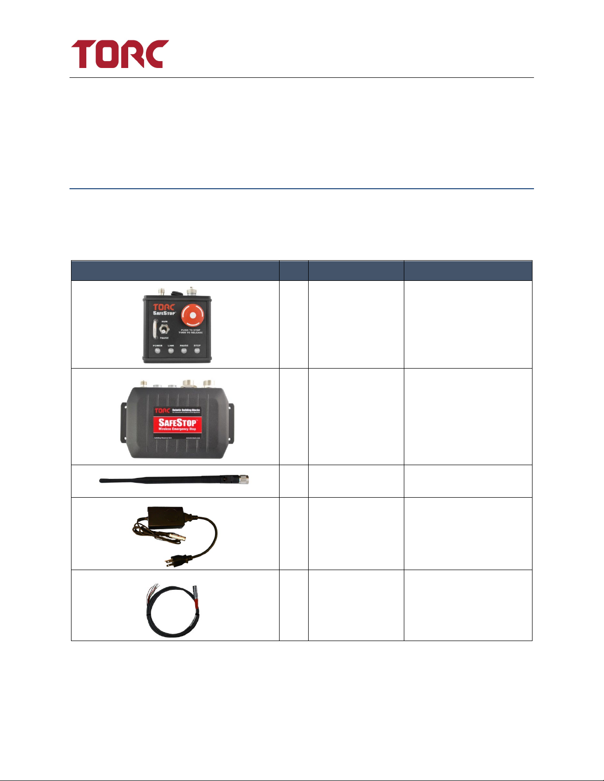
After unpacking the contents, verify the contents of the package includes the following items:
Qty Part Number Description
1 SS03TX** SafeStop® Transmitter unit
1 SS03RX** SafeStop® Receiver unit
2 ANT**01 Flexible Antenna (900 MHz
antenna shown)
1 SS03ACC-1 AC Power Adapter /
Charger for SafeStop®
Transmitter
1 SS03SFT 60” Safety Cable for
SafeStop™ Receiver

SafeStop®User Manual, Version 2.0
Manual, Version 2.0
8
Qty Part Number Description
1 SS03PWR 60” Power Cable for
SafeStop™ Receiver
2 SS03ETH Ethernet Plugs for
SafeStop Receiver
2 SS03ECP Ethernet Caps for SafeStop
Receiver
** Designates the frequency band: 04= 400 MHz, 09= 900 MHz, 13= 1.3 GHz, 24= 2.4 GHz
4.2 Optional Accessories
Accessory Part Number Function
External Emergency Stop Button
SS03A001 Allows the user to place an
Emergency Stop button on the
exterior of a vehicle. Magnetic
base with hard mount points.
External Emergency Override Button
SS03A002 Allows the user to place an
Emergency Override button on
the exterior of a vehicle. Magnetic
base with hard mount points.
Transmitter Car Charger
SS03A003 Provides the user the ability to
conveniently charge the
SafeStop® transmitter from any
standard 12V automobile outlet.

SafeStop®User Manual, Version 2.0
Manual, Version 2.0
9
Accessory Part Number Function
Transmitter Bind Plug
SS03A004 Allows the pairing of a transmitter
unit to any receiver.
Serial Interface Cable
SS03A005 Allows the user to interface with
the receiver using the legacy RS-
232 interface.
ANT**02 External high gain antenna with
magnetic mount. (900 MHz
antenna shown)
*Standard RAM mount accessories are available for a variety of transmitter mounting options.
SafeStop®User Manual, Version 2.0
Manual, Version 2.0
10
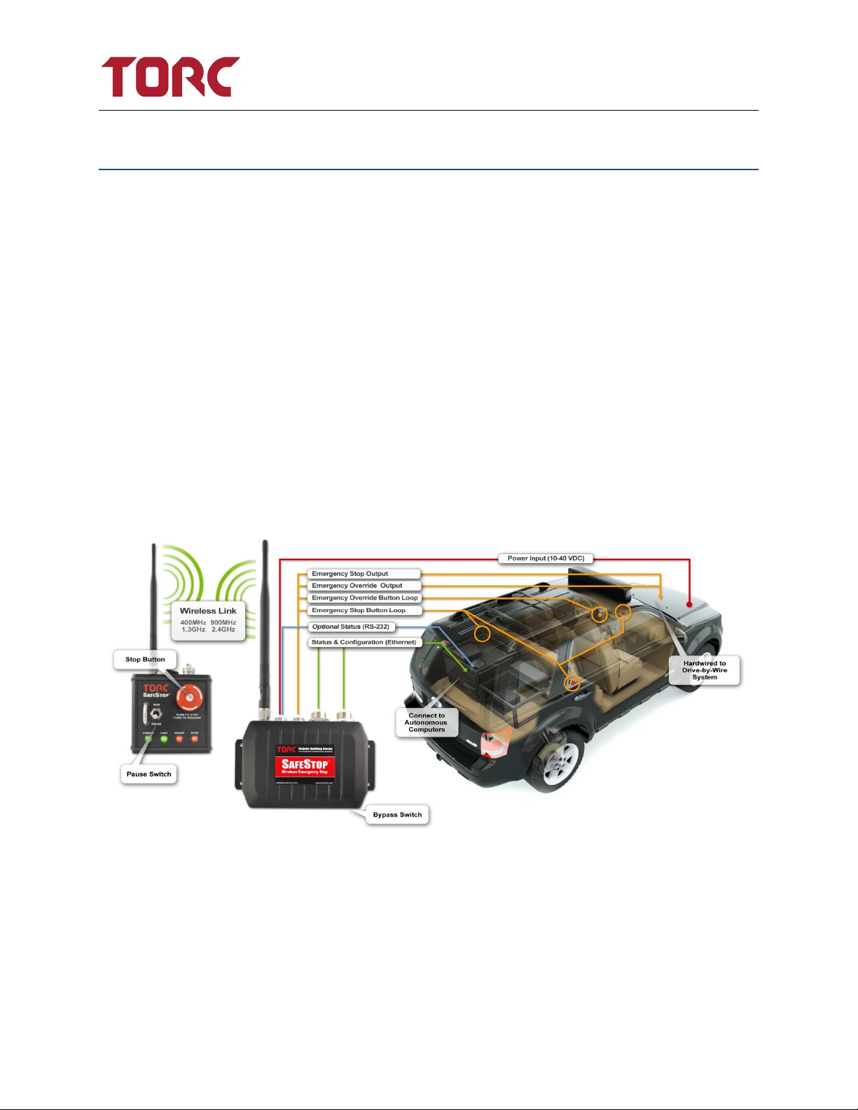
5. Product Overview
The SafeStop® is a multi-level wireless emergency stop system, consisting of the SS03TX
transmitter and the SS03RX receiver. The SafeStop system provides the ability to safely command
an unmanned or autonomous ground vehicle to pause or stop from a remote location up to six
miles away. SafeStop is not intended to be used outside of an unmanned or autonomous ground
vehicle application and should always be used in combination with procedural and physical
safety measures. The compact and lightweight transmitter contains an internal rechargeable
battery that enables continuous operation for up to 12 hours. Two hardware outputs are
available for use on the SS03RX receiver: an emergency stop output and an emergency override
output. Each of these outputs can be overridden with hardwired external buttons, however only
the emergency stop output is remotely controlled by the SS03TX transmitter. The status of all of
the outputs and inputs can be read from a simple TCP interface through either of the two
Ethernet ports on the receiver. An audible alarm and indicator lights provide user feedback of
system state, link status, and battery life. System configuration and firmware updates are
accessed using a web-based configuration interface. For manned operation, the wireless link may
also be disabled using a bypass switch on the receiver.
Figure 5-1: System Integration Example

SafeStop®User Manual, Version 2.0
Manual, Version 2.0
11
The SafeStop has three safety modes: pause, emergency stop, and emergency override. Pause
mode is intended to indicate a temporary pause in autonomous or unmanned vehicle operation
and is considered to be a software only condition. There is no hardware output associated with
the pause state. Emergency stop mode is intended to indicate a serious hardware or software
condition that should cause the vehicle to be immediately disabled. The hardware emergency
stop output is controlled by a red emergency stop button on the transmitter. Emergency override
mode is intended to be used to be a hardware only condition that entirely bypasses the SafeStop
embedded software to disable the system.
The safety architecture of the SafeStop receiver implements the use of two independent
processors that continuously monitor the system. For a vehicle to be placed in a running state,
both processors must be in agreement. If a discrepancy is detected, each processor has the ability
to individually place the system in an emergency stop state. In addition, the code on the
secondary processor on the receiver meets the Motor Industry Software Reliability Association
Guidelines for the use of the C language in critical systems (MISRA-C:2004). The SafeStop receiver
also includes redundant network ports and power inputs.
Multiple SS03 transmitters may be used to control a single SS03 SafeStop™ receiver. Configured
through the webpage, you may select up to 10 SafeStop™ transmitters to simultaneously control
a single SafeStop™ receiver. The effective range of the SafeStop™ system can be increased by
utilizing multiple transmitters. See Section 14.8 for examples on proper usage with multiple
transmitters.
WARNING: If multiple transmitters are connected to a SafeStop receiver, all
transmitters must lose communication with the receiver for the Timeout Action to
trigger. Do not leave any SafeStop transmitters on and unattended.

SafeStop®User Manual, Version 2.0
Manual, Version 2.0
12
6. Product Specifications
Wireless Performance
Operating Distance with Single Transmitter:6 miles(1) (line-of-sight)
Update Rate: 20 Hz
Wireless Link
Frequency Band: 902-928MHz(2) (Other frequencies available)
Modulation: FHSS GFSK
Hopping Channels: 112(2)
Transmit Power: 1W(3)
FCC Approved: Yes
Transmitter Electrical
SS03TX Battery Life: 12 hours(1)
SS03TX Input Voltage (charging):
SS03TX Power Consumption (12 VDC):
12/24 VDC, +/- 10%
15 W
OEM Transmitter Electrical
SS03OT Input Voltage (VIN): 10 - 32 VDC
SS03OT Power Consumption (12 VDC): 2.5 W
Receiver Electrical
SS03RX Input Voltage (VIN):
SS03RX Power Consumption (12 VDC):
10 - 40 VDC
8 W (Typical), Max power dependent on output load
Vehicle Interface /Output Ratings
Digital Communications: TCP/IP over Ethernet
(serial optionally available)
Emergency Stop Output Rating: 1.5A Continuous (sink or source)
Emergency Override Output Rating:
Emergency Stop Output Min Voltage:
Emergency Override Output Min Voltage:
1.5A Continuous (sink or source)
VIN – 2.4V
VIN – 2.4V

SafeStop®User Manual, Version 2.0
Manual, Version 2.0
13
User Interface
User Settings: Web browser configuration interface
Stop Input: Standard mushroom type stop button
(50,000 Operations Minimum)
Pause Input: Guarded toggle switch
(50,000 Operations Minimum)
Bypass Mode: Momentary pushbutton sequence
Visual Indicators: Bicolor LEDs for Power, Link, Pause, and Stop
Audible Alarm: Tone emitted for link lost and low battery
Environmental
Operational Temperature: -20°C to 70°C
Operational Humidity: 10% to 90%, non-condensing
Operational Shock Rating: 15 g
______________________________
1: Performance data based on optimal conditions
2: Australian / New Zealand units (SS03**09-AU) are frequency limited to 915 – 928 MHz with 55 hopping channels

SafeStop®User Manual, Version 2.0
Manual, Version 2.0
14
7. SafeStop® Transmitter
Item Description
1 Power Status Indicator
2 Link Status Indicator
3 Pause Status Indicator
4 Stop Output Indicator
5 Emergency Stop Button
6 Run/Pause Toggle Switch
7 Flexible Antenna (900 MHz antenna shown)
8 Power Switch
9 Charging Receptacle
10 Charge Status Indicator
Figure 7-1: SafeStop™ Transmitter Callouts

SafeStop®User Manual, Version 2.0
Manual, Version 2.0
15
7.1 Transmitter Switch Detail
There are three switches located on the transmitter: the Power rocker switch, the Pause/Run toggle
switch, and the Emergency Stop button.
When the Power rocker switch is in the “1” position, the transmitter is powered. With the switch in
the “0” position, the transmitter is shut down and will no longer receive or transmit data.
The Pause/Run toggle switch is used to update the status message sent over TCP/IP or serial by the
receiver. Flip the switch up to put the system in run mode, and down to put the system in pause
mode. For details of this message, see section 9.
The Emergency Stop button is a push-to-stop/turn-to-release style mushroom button and controls
the emergency stop output line on the receiver. When pushed, the emergency stop output is pulled
to GND, and when released the emergency stop output is connected to VIN.
7.2 Transmitter Power Receptacle
The transmitter Power Receptacle is used for charging the internal rechargeable battery and
powering the transmitter from an external power source such as the transmitter car charger (P/N:
SS03A003).
WARNING: Do not leave the SafeStop™ transmitter
unattended while
charging the battery.
WARNING: Only charge the battery using an approved power adapter.
WARNING: Only charge the battery at room temperature.
WARNING: Replace the included connector end cap when finished
charging the transmitter. The transmitter environmental ratings are only
valid when mated to the charger or the end cap is installed.

SafeStop®User Manual, Version 2.0
Manual, Version 2.0
16
Pin Description
1 Power Input
2 Factory Use Only
3 Ground (GND)
4 Factory Use Only
5 Factory Use Only
6 Factory Use Only
7 Factory Use Only
8 Factory Use Only
Figure 7-2: Transmitter Power Receptacle Detail

SafeStop®User Manual, Version 2.0
Manual, Version 2.0
17
7.3 Transmitter LED Indicator Detail
Table 7-1: Transmitter LED Detail
Indicator Status Meaning
Power Off Unit power is off
Red Less than 20% battery life remaining
Green Unit power is on
Link Red Communications link has been lost
Green Communications link is active
Pause Off Pause message state is unknown due to lost link
Red Receiver is in Pause mode
Green Receiver is in Run mode
Stop Off State of Stop output is unknown due to lost link
Red Stop output on receiver is pulled to GND
Green Stop output on receiver is connected to Vin
Charge Status Off Charger Disconnected / Error
Orange Charging
Green Charge Complete
Red Charge Error

SafeStop®User Manual, Version 2.0
Manual, Version 2.0
18
7.4 Transmitter Audible Alarm
The SafeStop™ transmitter features an audible alarm to indicate an error condition that requires
immediate user intervention. If the communication link is lost, the SafeStop transmitter is no
longer in communication with the receiver, and the transmitter will emit a constant tone. The
transmitter needs to be brought back within range of the receiver before operation can resume.
If the battery drops to approximately 20% of its total capacity, the audible alarm will start to
sound 3 short tones every 5 seconds. If this occurs, power the transmitter off external power using
either the supplied AC adapter (P/N: SS03ACC) or optional DC adapter (P/N: SS03DCA) to charge
the battery. The low battery audible alarm will turn off shortly after the transmitter is powered off
external power.
Table 7-2: Transmitter Audible Alarm Detail
Alarm Meaning
Continuous Communication link with receiver has been lost
Three Short Tones Less than 20% battery life remaining

SafeStop®User Manual, Version 2.0
Manual, Version 2.0
19
8. SafeStop® OEM Transmitter
NOTE: The OEM Transmitter has been discontinued on newer models and may
not be present in the newer systems.
Item Description
1 Power Status Indicator
2 Link Status Indicator
3 Pause State Indicator
4 Stop Output Indicator
5 User Interface Connector
6 Wireless Modem
7 MMCX RF Connection
8 External Modem Connector
9 DIP Switches
Figure 8-1: OEM Transmitter

SafeStop®User Manual, Version 2.0
Manual, Version 2.0
20
8.1 OEM Transmitter User Interface Connector Detail
Mating Connector Manufacturer: JST
Mating Connector Manufacturer Part Number: PADP-16V-1-S
Table 8-1: Transmitter User Interface Connector Detail
PIN Function
1 POWER
2 GROUND
3 POWER
4 GROUND
5 Factory Use Only (Connect Directly to Power Pin)
6 STOP LOOP LOW
7 N.C.
8 STOP LOOP HIGH
9 Factory Use Only
10 Factory Use Only
11 Factory Use Only
12 Factory Use Only
13 PRIMARY RS-232 RX, RS-422 RX-
14 PRIMARY RS-422 RX+
15 PRIMARY RS-232 TX, RS-422 TX-
16 PRIMARY RS-422 TX+
8.2 OEM Transmitter DIP Switch Detail
Table 8-2: OEM Transmitter DIP Switch Detail
Dip Switch Function Off On
1 RESERVED (Keep in OFF position) NORMAL NONE
2 PRIMARY SERIAL MODE RS-232 RS-422
3 BIND MODE DISABLED ENABLED
4 RESERVED (Keep in OFF position) NORMAL NONE
5 RESERVED (Keep in OFF position) NORMAL NONE
This manual suits for next models
5
Table of contents
Popular Protection Device manuals by other brands


dol sensors
dol sensors 140245 Technical user guide

Textron
Textron GREENLEE 01761-03XL quick start guide

SILENTex
SILENTex Natural User instructions

Orascoptic
Orascoptic EASE-IN-SHIELDS Instructions for use

Aquadistri
Aquadistri SuperFish Bird & Cat Protector user manual

Intermatic
Intermatic IG3240FMP33 installation instructions