Tormatic Novotron 171 User manual
Supply Voltage
230VAC +/- 10%
1,2VA
Relay Outputs
230VAC / 3A
50VDC / 1A
Channel 2
Channel 1
Novotron 171
Novotron 172
E 43-1
E 43-2
BB
D
CA
Novotron 172
E43-2
3b
Channel 1
Channel 2
F
G
E
g
+
E F D
Relay Output
1 x 1 x
2 x 2 x Flip-Flop
3 x 3 x
4 x 4 x
5 x 5 x t
5
2 sec
5 Sec.
1.
2. 3.
4.
1 x
10 sec.
3.1.
2.
6 x.
0 - 59 sec.
1 x
1. 2. 3.
0 - 90 min.
4.
1 x
E F D
Relay Output
t
6 x 1 x t = 0 ... 60 sec.
7 x 2 x t = 0 ... 90 min.
5.
45a
5c
1
ABB
D
C
Novotron 171
E43-1
2a
2b
6
7 8
WN 919002-25-6-50 11/17
2 sec. 2 sec. 2 sec.
Code 01
Code 02
. . .
. . .
Code 99
5b
2 x
3a

Empfangsfrequenz: 433,92MHz,AM
Receiver category: 3 der EN 300 220-1
Speicherplätze: 99 Codes
Codierung: 12Bit, Multibit und KeeLoq
Temperaturbereich: + 60°C
-20°C
Schutzart: IP54
EU-Konformitätserklärung
Diese Funkfernsteuerung entspricht den
Anforderungen der
EMV-Richtlinie 2014/30/EU und
Niederspannungsrichtlinie 2014/35/EU.
Hiermit erklärt TORMATIC, dass der
Funkanlagentyp der Richtlinie 2014/53/EU
entspricht. Der vollständige Text der EU-
Konformitätserklärung ist unter der folgenden
Internetadresse verfügbar:
www.tormatic.de/nc/downloads.html
Dirk Gößling Dortmund, 01.06.2017
- Geschäftsführer -
TORMATIC
Eisenhüttenweg 6, D-44145 Dortmund
www.tormatic.de
• Installationsanweisung
Die Installation ist nur durch entsprechend
qualifizierte Fachkräfte bzw. qualifizierten
Elektroinstallateur durchzuführen!
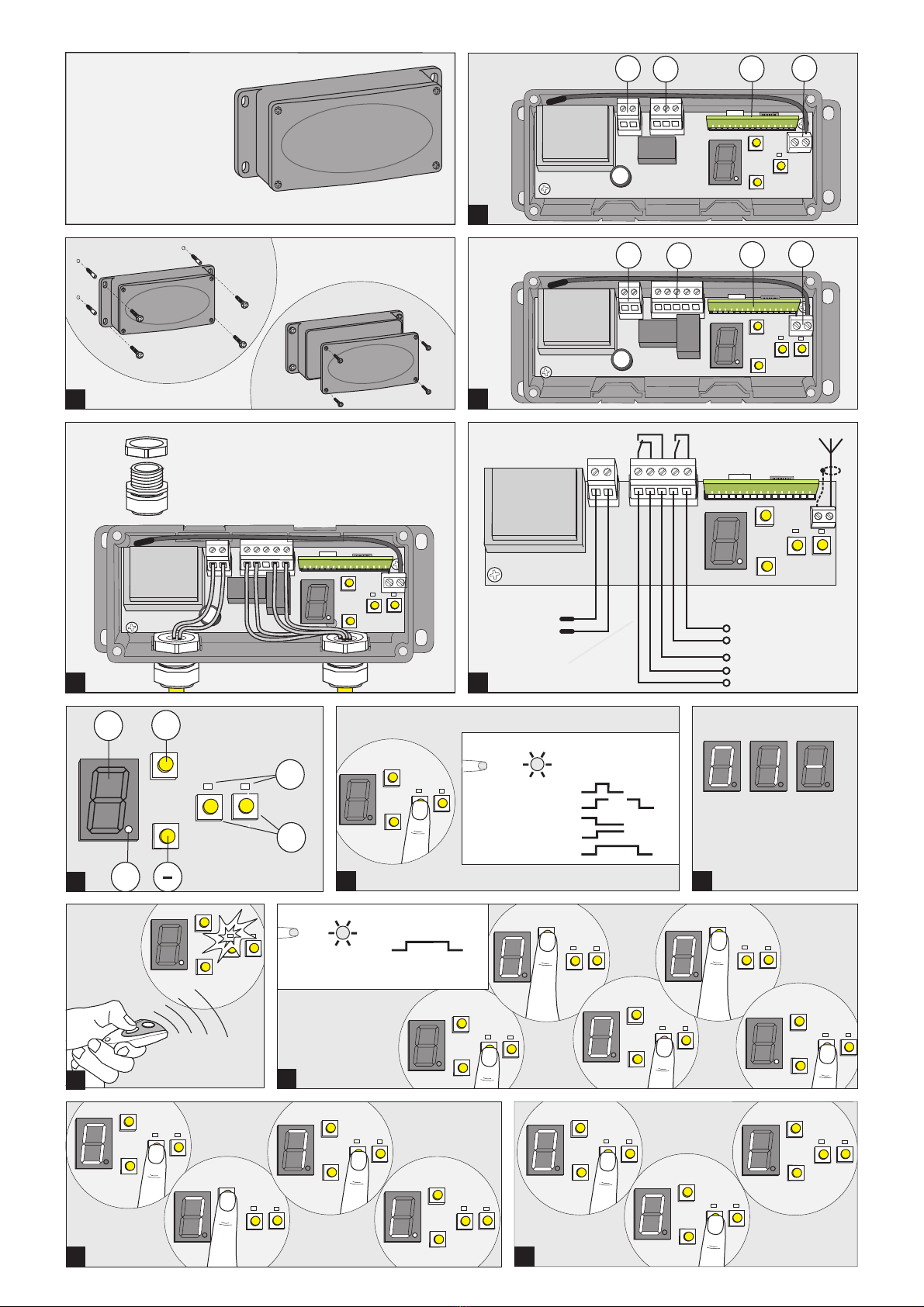
Montage
Übersicht Komponenten
AEmpfängermodul
BAnschluss Antenne, linker Anschluss für
Abschirmung
CVersorgungsspannung
DRelaisausgänge
Anschließen
Nur geeignete Leitungen verwenden.
Anschlusswerte beachten.
Dichtigkeit im Außenbereich gewährleiten.
- Nur mit kompletten Gehäuse montieren
- Leitungen nur von unten her einführen
- passende Durchführung am Würgenippel
sorgfältig mit dem Cutter scheiden.
- ggf. Kabelverschraubungen M16 verwenden.
- Die Stromversorgung muss über eine allpolige
Abschaltung verfügen (z.B. Netzstecker).
Programmierung
EProgrammier-Tasten für Kanal 1, Kanal 2
FLED Kanal 1, LED Kanal 2
GZiffernanzeige dient zur Anzeige des
Speicherplatzes
g. Punktanzeige, leuchtet bei Betriebsbereitschaft
Tasten zum Auswählen der Speicherplätze.+/-
1
2
3
4
• Allgemeine Informationen
• Sicherheit
Achtung wichtige Sicherheitsanweisungen:
Für die Sicherheit von Personen ist es wichtig,
diesen Anweisungen Folge zu leisten. Diese An-
weisungen sind aufzubewahren. Alle Anweisungen
beachten, falsche Montage kann zu ernsthaften
Verletzungen führen.
Vor Beginn sämtlicher Arbeiten am Produkt die
Betriebsanleitung, insbesondere das Kapitel
Sicherheit und die jeweiligen Sicherheitshinweise,
vollständig lesen. Das Gelesene muss verstanden
worden sein. Es könnten von diesem Produkt
Gefahren ausgehen, wenn es nicht fachgerecht,
unsachgemäß oder nicht bestimmungsgemäß
verwendet wird. Bei Schäden, die aufgrund der
Nichtbeachtung dieser Anleitung entstehen, erlischt
die Herstellerhaftung.
• Anwendungsbereich
Empfänger in 1- oder 2-Kanalausführung in 433,92
MHz. Umstellung der Frequenz in 40,685 oder
868,3MHz ist durch Tauschen des Empfangsmoduls
möglich.
Die Funkfernsteuerung eignet sich besonders zum
Schalten von Beleuchtungen, Torantrieben,
Alarmanlagen, Springbrunnen usw.
Der Empfänger darf nicht für Steuerung von
Geräten, die der Sicherheit oder dem K omf ort f ür
Personen dienen, eingesetzt werden (z.B.: Notruf,
Kräne).
• Gefahren, die vom Produkt ausgehen können
Das Produkt ist bei bestimmungsgemäßer
Verwendung betriebssicher. Dennoch bleibt ein
Restrisiko bestehen!
Das Produkt arbeitet mit hoher elektrischer
Spannung. Vor Beginn der Arbeiten an elektrischen
Anlagen ist folgendes zu beachten:
1. Freischalten
2. Gegen Wiedereinschalten sichern
3. Spannungsfreiheit feststellen
• Veränderungen und Umbauten am Produkt
Zur Vermeidung von Gefährdungen und zur
Sicherung der optimalen Leistung dürfen am Pro-
dukt weder Veränderungen noch An- und Umbau-
ten vorgenommen werden, die durch den Hersteller
nicht ausdrücklich genehmigt worden sind.
• Demontage
Vor Demontage ist das Gerät stromlos zu schalten.
• Entsorgung
Es sind die entsprechenden Ländervorschriften zu
beachten. Elektro- und Kunststoffteile entsprechend
sortieren.
• Typenschild
Das Typenschild befindet auf dem Gehäuse. Die
angegebenenAnschlusswerte sind zu beachten.
• Verpackung
Entsorgung der Verpackungsmaterialien stets
umweltgerecht und nach den geltenden örtlichen
Entsorgungsvorschriften vornehmen.
• Technische Daten
Typ: E43-1, E43-2
Anschlusswerte: 230 V / 50 Hz / 1,2VA
Schutzklasse: II, schutzisoliert
Schaltausgänge: potentialfrei
Kanal 1 1 x Wechsler
Kanal 2(E43-2) 1 x Schließer
SchaltleistungAC 250 V / 3A
Schaltleistung DC 50 V / 1A
4
13
Mit Betätigung der Programmiertaste wird in denE
Programmiermodus gewechselt. Die Punktanzeige
gerlischt.
Es gibt 5 unterschiedliche Relais-Funktionen, die
über die Anzahl der Betätigungen der Taste für denE
entsprechenden Kanal und Speicherplatz auszu-
wählen sind.
Relais-Funktionen:
1. Impuls
2. Flip-Flop
3. gezieltAus
4. gezielt Ein
5. Timerfunktion, Zeit kann von 1 Sek. bis zu 90
Minuten eingestellt werden.
Handsender einlernen
5a Taste entsprechend gewünschter Funktion xE
mal betätigen. LED blinkt x mal.
5b Ziffernanzeige zeigt den Speicherplatz an.G
Notieren Sie die den Speicherplatz, Kanal und
den Handsender.
5c Taste am Handsender betätigen.
LED Flackert auf. Punktanzeige leuchtet.E g
Der Code vom Handsender wurde erfolgreich
eingelernt.
Timer einstellen
Die Laufzeit des Timers setzt sich aus der
Einstellung von Sekunden und Minuten zusammen.
1. Betätigen Sie die Taste 6x. LED blinkt 6x.E
2. Sie können mit den Tasten +/- die Sekunden
für den Timer einstellen.
3. Betätigen Sie die Taste . LED blinkt 7x.E
4. Sie können mit den Tasten +/- die Minuten für
den Timer einstellen.
5. Taste betätigen. Punktanzeige leuchtet.E g
Löschen eines Speicherplatzes
Aus den Aufzeichnungen wählen Sie den Kanal und
den Speicherplatz aus.
1. Betätigen Sie kurz die Taste E
2. Wählen Sie mit den Tasten den zu löschenden+/-
Speicherplatz aus.
3. Betätigen Sie die Taste erneut und halten SieE
sie für 5 Sekunden gedrückt. LED flackert,
Punktanzeige leuchtet wieder.g
Der Speicherplatz ist gelöscht und kann wieder neu
belegt werden. Gelöschte Speicherplätze werden
mit der Punktanzeige angezeigt.g
Löschen aller Speicherplätze
Für jeden Kanal können alle eingelernten Codes
komplett gelöscht werden.
1. Taste kurz betätigen.E
2. Betätigen Sie die Taste erneut und halten SieE
sie für 10 Sekunden gedrückt. LED flackert,
Punktanzeige leuchtet.
Alle Speicherplätze wurden gelöscht und können
wieder neu belegt werden.
Abhilfe bei Empfangsproblemen
Die Antenne kann im Gehäuse bleiben. Bei
schwierigen Empfangslagen (z.B. Keller) muss eine
externeAntenne (Zubehör) angeschlossen werden.
Bei gestörtem Frequenzband kann durch Tauschen
des Empfängermoduls ein anderer Frequenz-A
bereich 40,685MHz oder 868,3MHz benutzt werden.
- Versorgungsspannung abschalten
- Empfängermodul abziehen
- neues Modul seitenrichtig aufstecken
- Wiedereinschalten und neue Handsender
einlernen.
5
6
7
8
D
Diese Montage-, Bedienungs- und Wartungsanleitung ist während der gesamten Nutzungsdauer aufzubewahren!
Temperature range: + 60°C
-20°C
Protection type: IP 54
EU Declaration of Conformity
The radio remote control device complies with the
requirements of
EMC directive 20 4/ /E , and1 30 U
L 14 3 Uow voltage directive 20 / 5/E .
TORMATIC hereby declares that the type of radio
equipment conforms to Directive 2014/53/EU.
Please refer to the Internet for the full text of the EU
De c l a r a t i o n of C o nf o r m i t y : w w w. t or m a-
tic.de/nc/downloads.html
Dirk Gößling Dortmund, 01.06.2017
- Managing Director -
TORMATIC
Eisenhüttenweg 6, D-44145 Dortmund
www.tormatic.de
• Installation instructions
The device must be installed by persons with
appropriate professional qualification or by a
qualified electrical fitter.
Installation
Component overview
AReceiver module
BAerial socket, socket on the left for
screening
CSupply voltage
DRelay outputs
Connection
Use only suitable cables.
Be sure that the connection data match the
nameplate data.
Ensure tightness when installed outdoors.
- Install only with the complete housing
- Install cables only from below
- Carefully prepare a suitable leadthrough at
the self-sealing grommet with the cutter.
- Use M16 screw cable glands if necessary.
- The power supply must include an all-pole
disconnect (e.g., a mains plug).
Programming
EProgramming keys for channel 1,
channel 2
FLED channel 1, LED channel 2
GDigits specify the memory location
g. Point display signals that the device is
ready for service
+/- Keys for selecting a memory location.
Pressing the programming key activates theE
programming mode. The point light extinguishes.g
1
2
3
4
• General Information
• Safety
Before commencing any work on the product,
carefully read through the operating instructions
from start to finish, in particular the section entitled
“Safety”and the related safety advice. It is important
for you to have understood what you have read. This
product could prove hazardous if not used properly
as directed or in accordance with the regulations.
Any damage occurring as a result of non-compliance
with these instructions shall render the manufactu-
rer’s liability null and void.
• Application
Receivers of 1- or 2-channel design operating at
433.92 MHz. Frequency conversion to 40.685 or
868.3 MHz is possible by replacing the receiver
module.
The radio remote control function is particularly
suitable for switching lamps, door drives, alarm
systems, fountains, etc.
The receiver must not be used for controlling devices
used for applications involving the safety or comfort
of persons (e.g., emergency call, cranes).
• Hazards that may emanate from the product
When used properly as intended, the product is safe
and reliable to operate.
Nevertheless, a residual risk will always remain!
The product runs on a high electrical voltage. Before
commencing any work on electrical systems, please
observe the following:
1. Disconnect from the power supply
2. Safeguard to prevent a power restart
3. Check that the electricity supply is cut off.
• Changes and modifications to the product
In order to prevent hazards and ensure optimum
performance, no changes, modifications or
conversions may be made to the product that have
not been expressly approved by the manufacturer.
• Removal
Disconnect the device from the power source before
removing it.
• Disposal
Observe the corresponding country-specific
regulations.
• Data plate
The date plate is located under the control panel
cover. Observe the specified power rating.
•Packaging
Always dispose of the packaging in an
environmentlly-friendly manner and in accordance
with the local regulations on disposal.
• Technical data
Type: E43-1, E43-2
Connections: 230 V / 50 Hz / 1.2VA
Protection class: II, with protective insulation
Switching outputs: floating
Channel 1 1 x CO contact
Channel 2 (E43-2) 1 x make contact
Switching capacity
2 3AC 50 V / A
Switching capacity
DC 50 V / 1A
Receiving frequency: 433.92 MHz, AM
Receiver category: 3 of EN 300 220-1
Memory locations: 99 codes
Encoding: 12 bit, multibit and KeeLoq
4
13
There are 5 different relay functions which can be
selected with by presses of the key for theE
appropriate channel and memory location.
Relay functions:
1. Impulse
2. Flip-flop
3. selective Off
4. selective On
5. Timer function, the time can be set from
1 second to 90 minutes.
Teaching the handheld transmitter
5a Press key as many times as requiredE
for the function you want to use. The key
flashes x times.
5b Digit display indicates the memoryG
location. Take down the memory
location, channel and handheld
transmitter.
5c Press the button at the handheld
transmitter.
LED flashes momentarily. PointE
display lights.g
The code teaching of the handheld
transmitter was successful.
Setting the timer
The timer setting comprises seconds and minutes.
1. Press key 6 times. LED flashes 6E
times.
2. You can set the timer seconds with the
keys .+/-
3. Press key . LED flashes 7 times.E
4. You can set the timer minutes with the
keys .+/-
5. Press key . Point display lights.E g
Deleting a memory location
Select the channel and the memory location from the
records.
1. Briefly press key .E
2. Select the memory location you want to
delete with keys .+/-
3. Press key again and hold it depressedE
for about 5 seconds. LED flickers.
Point display lights again.g
The memory location is deleted and new data can
be stored there. Deleted memory locations can be
displayed by point display .g
Deleting all memory locations
All taught codes can be deleted completely for each
channel.
1. Briefly press key .E
2. Press key again and hold it depressedE
for about 10 seconds. LED flickers,
Point display lights.g
All memory locations have been deleted and new
data can be stored.
Remedying reception problems
The antenna can remain in the housing. If reception
is poor (e.g., in the basement of a house), connect an
external antenna.
If the frequency band is disturbed, the reception
module can be replaced and another frequencyA
range 40.685 MHz or 868.3 MHz used.
- Disconnect the power supply
- Pull off the reception module
- Install the new module; make sure the
side is correct
- Turn on the device and teach the new
handheld transmitter.
5
6
7
8
GB
Retain these installation, operating and maintenance instructions for the full duration of the operator’s service life!
FR
Conserver cette notice de montage, d'utilisation et de maintenance pendant toute la durée d'utilisation !
Fréquence de réception : 433,92MHz, AM
Catégorie de récepteur : 3 de EN 300220-1
Emplacements mémoire : 99 Codes
Codage : 12 bits, multibit et
KeeLoq
Plage de températures : + 60°C
-20°C
Types de protection : Ip54
Déclaration de conformité UE
La télécommande radio répond aux exigences
d 1 30es directives CEM 20 4/ /CE et de la directive
sur les basses tensions 20 / 5/CE14 3 .
Par la présente, TORMATIC déclare que le type
d'installation radioélectrique se conforme à la
directive 2014/53/UE.
Le texte complet de la déclaration de conformité
UE est disponible à l'adresse internet suivante :
www.tormatic.de/nc/downloads.html
Dirk Gößling Dortmund, 01.06.2017
- Managing Director -
TORMATIC
Eisenhüttenweg 6, D-44145 Dortmund
www.tormatic.de
• Instructions d'installation
L'installation est exclusivement réservée à des
spécialistes qualifiés ou à un électricien installateur
qualifié !
Montage
Vue d'ensemble des composants
AModule récepteur
BRaccord d'antenne, raccord gauche du blindage
CTension d'alimentation
DSortie de relais
Branchement
N'utiliser que des lignes appropriées.
Respecter les paramètres de branchement.
À l'extérieur, garantir l'étanchéité.
- Toujours monter le boîtier complet.
- Les lignes ne doivent arriver que par le bas.
- Au niveau du nipple d'étranglement, découper le
passage soigneusement avec un cutter.
- Utiliser le cas échéant des presse-étoupes M16.
- L'alimentation électrique doit comporter un
moyen permettant de couper tous
les pôles (une fiche mâle par exemple.
Programmation
ETouches de programmation pour les canaux 1
et 2
LED Canal 1, LED Canal 2F
L'afficheur numérique indique l'emplacementG
mémoire
g. Affichage de point, s'allume en veille
Touche pour choisir les emplacements+/-
mémoire.
1
2
3
4
• Informations générales
• Sécurité
Attention, consignes de sécurité importantes :
Pour assurer la sécurité des personnes, il est
important de respecter les présentes instructions. Il
faut conserver ces instructions. Respecter toutes les
instructions ; un montage erroné peut entraîner des
blessures graves.
Avant d'entamer tous travaux sur le produit, veuillez
lire intégralement la notice d'instructions et en
particulier le chapitre Sécurité plus les consignes de
sécurité respectives. Il faut avoir compris le contenu
de la notice d'instructions. Du produit peuvent
émaner des risques s'il n'est pas utiliser
p r o f e s s i o n n e l l e m e n t , c o r r e c t e m e n t o u
conformément à l'usage prévu. En cas de
dommages dus au non-respect de cette notice, la
responsabilité du fabricant devient caduque.
• Champ d'application
Récepteur, version à 1 ou 2 canaux, en 433,92 MHz.
Il est possible d'utiliser d'autres fréquences (40,685
ou 868,3 MHz) en changeant le module récepteur.
La télécommande radio convient particulièrement
pour commuter des éclairages, téléouvertures de
portails, installations d'alarme, fontaines, etc.
Le récepteur ne doit pas être utilisé pour piloter des
appareils affectés à la sécurité et au confort de
personnes (par ex. appel d'urgence, grues).
• Dangers susceptibles d'émaner du produit
Le produit est d'une utilisation sûre en service à
condition qu'elle soit conforme. Un risque résiduel
n'en demeure pas moins.
Le produit fonctionne sous une tension électrique
élevée. Consignes à respecter avant de travailler sur
des installations électriques :
1. Mettre hors tension
2. Sécuriser pour empêcher un réenclenchement
3. Vérifier l'absence de tension
• Modifications et transformations du produit
Pour éviter des risques et assurer une performance
optimale, il ne faut pas modifier le produit, ne rien
rapporter contre lui et ne rien convertir si le fabricant
n'a pas expressément autorisé ces opérations.
• Démontage
Avant le démontage, mettre l'appareil hors tension.
• Élimination
Il faut respecter les règlements nationaux
correspondants. Trier les pièces électr(on)iques et
en plastique.
• Plaque signalétique
La plaque signalétique est sur le boîtier. Tenir
compte du paramétrage de branchement.
• Emballage
Éliminer les matériaux d'emballage en respectant
toujours l'environnement et les prescriptions
d'élimination localement applicables.
• Caractéristiques techniques
Type : E43-1, E43-2
Puissances raccordées : 230 V / 50 Hz /
1,2VA
Classe de protection : II, avec isolation
protectrice
Sorties de commutation : sans potentiel
Canal 1 1 x inverseur
Canal 2 (E43-2) 1 x contact de
travail
Puissance de commutation CA 250V/3A
Puissance de commutation CC 50V/1A
13
Pour entrer en mode de programmation, appuyer sur
la touche . Le point affiché s'éteint.E g
Il y a 5 fonctions relais différentes à choisir en
actionnant la touche le nombre de foisE
correspondant pour le canal et l'emplacement
mémoire correspondants.
Fonctions relais :
1. Impulsion
2. Flip-Flop
3. eArrêt ciblé
4. Marche ciblée
5. Fonction minuteur, temps réglable entre 1 sec.
et 90 minutes.
Programmation de la télécommande portative
5a Actionner la touche x fois suivant la fonctionE
souhaitée. La LED clignote x fois.
5b L'affichage de point indique l'emplacementG
mémoire. Notez l'emplacement mémoire, le
canal et la télécommande manuelle.
5c Actionnez la touche de la télécommande
manuelle.
La LED vacille. L'affichage du point s'allumeE
g. e code de la télécommande manuelle a étéL
programmé avec succès.
Réglage du minuteur
La durée du minuteur résulte du réglage des
secondes et des minutes.
1. Actionnez la touche 6 fois. La LED clignoteE
6 fois.
2. Avec les touches , vous pouvez régler les+/-
secondes du minuteur.
3. Actionnez la touche . La LED clignote 7 fois.E
4. Avec les touches , vous pouvez régler les+/-
minutes du minuteur.
5. Actionner la touche . L'affichage du pointE g
s'allume.
Effacer un emplacement mémoire
Dans les enregistrements, choisissez le canal et
l'emplacement mémoire.
1. Actionnez brièvement la touche E
2. À l'aide des touches , choisissez+/-
l'emplacement mémoire à effacer.
3. Actionnez à nouveau la touche etE
maintenez-la appuyée 5 secondes. La LED
vacille, l'affichage de point se rallume.g
L'emplacement mémoire est effacé et peut être
réaffecté. Les emplacements mémoire effacés sont
affichés à l'aide du point .g
Effacer tous les emplacements mémoire
Il est possible d'effacer tous les codes programmés
pour chaque canal.
1. Actionner brièvement la touche .E
2. Actionnez à nouveau la touche etE
maintenez-la appuyée 10 secondes. La LED
vacille, l'affichage de point s'allume.
Tous les emplacements mémoire ont été effacés et
peuvent être réaffectés.
Remèdes si problèmes de réception
L'antenne peut rester dans le boîtier. Si la réception
est mauvaise (cave par ex.), il faut raccorder une
antenne externe (accessoire).
Si la bande de fréquences est perturbée, le
changement du module récepteur permet d'utiliserA
une autre plage de fréquences (40,685MHz ou
868,3MHz).
- Couper la tension d'alimentation
- Retirer le module récepteur
- Enficher le nouveau module dans le bon sens
- Rallumer et programmer les nouvelles
télécommandes manuelles.
5
6
7
8
This manual suits for next models
3
Table of contents
Languages:
Other Tormatic Gate Opener manuals


