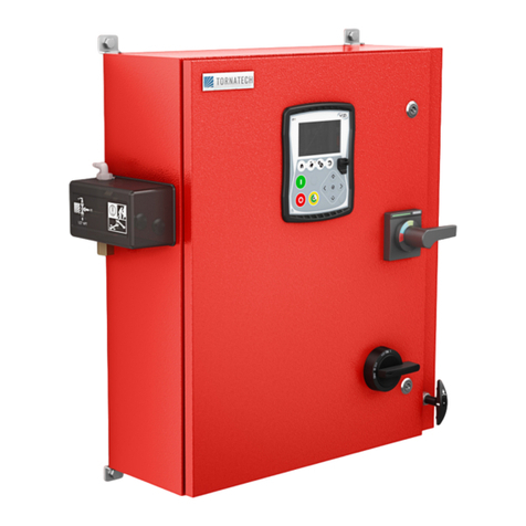
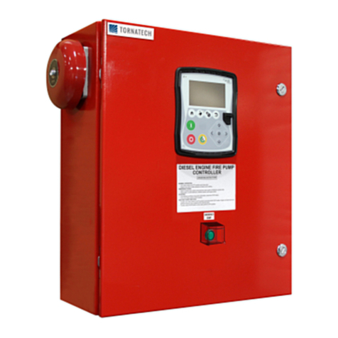
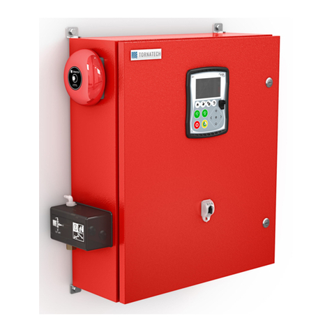
Tornatech VP series Manual

2018/10 1 VPX-MAN002-E REV4.DOCX4
INSTALLATION AND MAINTENANCE MANUAL FOR
ELECTRIC FIRE PUMP CONTROLLERS WITH
AUTOMATIC TRANSFER SWITCH
MODEL VPx + VPU

2018/10 2 VPX-MAN002-E REV4.DOCX4

2018/10 3 VPX-MAN002-E REV4.DOCX4
Table of content
GENERAL DESCRIPTION ............................................................................................................................. 6
1. TYPES OF ELECTRIC FIRE PUMP CONTROLLERS........................................................................... 6
1.1. ACROSS-THE-LINE STARTER..................................................................................................... 6
1.1.1. Model VPA: .............................................................................................................................. 6
1.2. REDUCED VOLTAGE STARTER.................................................................................................. 6
1.2.1. Model VPR: AUTOTRANSFORMER STARTER...................................................................... 6
1.2.2. Model VPS: SOLID STATE STARTER..................................................................................... 6
2. TYPES OF AUTOMATIC TRANSFER SWITCH .................................................................................... 7
2.1. Model VPU..................................................................................................................................... 7
3. METHODS OF STARTING / STOPPING............................................................................................... 8
3.1. methods of starting......................................................................................................................... 8
3.1.1. automatic start.......................................................................................................................... 8
3.1.2. manual start.............................................................................................................................. 8
3.1.3. remote manual start.................................................................................................................. 8
3.1.4. emergency start........................................................................................................................ 8
3.1.5. sequential start......................................................................................................................... 8
3.1.6. weekly start .............................................................................................................................. 8
3.2. methods of stopping....................................................................................................................... 8
3.2.1. manual stop.............................................................................................................................. 8
3.2.2. automatic stop.......................................................................................................................... 8
3.2.3. emergency stop........................................................................................................................ 8
4. variable speed pressure limiting control ................................................................................................. 9
4.1. General.......................................................................................................................................... 9
4.2. VARIABLE speed MODE............................................................................................................... 9
4.3. Preset speed mode........................................................................................................................ 9
4.4. bypass mode.................................................................................................................................. 9
4.5. STOP PUSH BUTTONS................................................................................................................ 9
5. TRANSFER SWITCH OPERATION SEQUENCE.................................................................................10
5.1. TRANSFER TO ALTERNATE POWER SOURCE........................................................................10
5.2. RETRANSFER TO NORMAL .......................................................................................................10
6. front panel .............................................................................................................................................11
6.1. generals........................................................................................................................................11
6.2. PRS DISPLAY ..............................................................................................................................11
6.3. PRS ANNUNCIATORs..................................................................................................................11
6.3.1. NORMAL POWER AVAILABLE ..............................................................................................11
6.3.2. SYSTEM Trouble.....................................................................................................................11
6.3.3. PHASE REVERSAL................................................................................................................12
6.3.4. Low system pressure...............................................................................................................12
6.4. Flange annunciators......................................................................................................................12
6.4.1. BYPASS MODE ......................................................................................................................12
6.4.2. VFD FAILURE.........................................................................................................................12
6.5. Audible alarm................................................................................................................................12
6.6. transfer switch –monitoring..........................................................................................................12
6.6.1. Alarm bell ................................................................................................................................12
6.6.2. Alternate POWER AVAILABLE ...............................................................................................12
6.6.3. Normal position........................................................................................................................12
6.6.4. Alternate position.....................................................................................................................12
6.6.5. Isolating switch in off position................................................................................................12
7. alarm contacts.......................................................................................................................................13
8. INSTALLATION.....................................................................................................................................14
9. LOCATION............................................................................................................................................14

2018/10 4 VPX-MAN002-E REV4.DOCX4
10. Mounting................................................................................................................................................14
10.1. wall mounting................................................................................................................................14
10.2. floor mounting...............................................................................................................................14
11. connections...........................................................................................................................................15
11.1. WATER CONNECTIONS..............................................................................................................15
11.2. ELECTRICAL CONNECTIONS ....................................................................................................15
11.2.1. ELECTRICAL WIRING............................................................................................................15
11.2.2. enclosure drilling......................................................................................................................15
11.2.3. INCOMING POWER CONNECTIONS ....................................................................................15
11.2.4. MOTOR CONNECTIONS........................................................................................................15
11.2.5. alarm contact connection.........................................................................................................15
11.2.6. connection to external device..................................................................................................16
12. START-UP AND TEST PROCEDURES................................................................................................17
12.1. VeRIFICATIONS...........................................................................................................................17
12.1.1. ELECTRICAL INSTALLATION................................................................................................17
12.1.2. PIPING INSTALLATION..........................................................................................................17
12.2. SETTINGS on the electronic boards.............................................................................................18
12.3. DIPSWITCH..................................................................................................................................18
12.3.1. PHASE REVERSAL(Ph Rev)..................................................................................................18
12.3.2. RUN PERIOD TIMER (RPT) ...................................................................................................18
12.3.3. SEQUENTIAL START TIMER (Seq Timer).............................................................................18
12.3.4. TEST (Test).............................................................................................................................18
12.3.5. PRESSURE UNIT (Pr Unit).....................................................................................................18
12.3.6. SERIAL (Serial).......................................................................................................................18
12.4. PRS...............................................................................................................................................19
12.4.1. pressure adjustment................................................................................................................19
12.5. SETTINGS on the sequential module (SM1) ................................................................................19
12.6. Timers...........................................................................................................................................19
12.6.1. T1 : Sequential start timer .......................................................................................................19
12.6.2. T2 : minimum run period timer.................................................................................................19
13. Variable speed drive (VFD) settings......................................................................................................20
13.1. NON-critical parameters................................................................................................................20
13.1.1. VFD power up / shutdown.......................................................................................................20
13.1.2. minimum speed.......................................................................................................................20
13.1.3. PRESET speed .......................................................................................................................20
13.1.4. Pressure SETPOINT...............................................................................................................21
13.1.5. gain..........................................................................................................................................21
13.1.6. INTEGRAL TIME.....................................................................................................................21
14. ACTUAL START-UP .............................................................................................................................22
14.1. CHECK MOTOR ROTATION........................................................................................................22
14.2. CHECK WRONG PHASE ROTATION INDICATION....................................................................22
15. PUMP START TEST.............................................................................................................................23
15.1. START FROM START PUSHBUTTON PB1.................................................................................23
15.2. START FROM REMOTE START STATION .................................................................................23
15.3. WATER PRESSURE CONTROL..................................................................................................23
15.3.1. MANUAL SHUTDOWN MODE................................................................................................23
15.3.2. AUTOMATIC SHUTDOWN MODE..........................................................................................24
15.4. START FROM EMERGENCY START HANDLE ..........................................................................24
16. Sequential module Programming instructions.......................................................................................25
16.1. How to adjust date ........................................................................................................................25
16.2. how to program a weekly test .......................................................................................................25
16.3. How to set SM1 in run mode.........................................................................................................26
16.4. How to set run period timer...........................................................................................................26
16.5. How to set SEQUENTIAL START timer........................................................................................26
17. PRS99 Programming instructions..........................................................................................................27

2018/10 5 VPX-MAN002-E REV4.DOCX4
17.1. How to read the display.................................................................................................................27
17.1.1. Top Line ..................................................................................................................................27
17.1.2. SECOND LINE........................................................................................................................27
17.1.3. THIRD LINE ............................................................................................................................27
17.1.4. FOURTH LINE.........................................................................................................................27
17.2. How to adjust the cut in / cut out pressure....................................................................................27
17.3. What is the flashing symbol on the second line ............................................................................28
17.4. Why 'Low System Pressure' LED is flashing.................................................................................28
17.5. How to adjust the date and time....................................................................................................28
17.6. How to print reports.......................................................................................................................29
17.7. How to replace the paper..............................................................................................................30
17.8. How to replace the ribbon.............................................................................................................30
17.9. How TO RETRIEVE PRESSURE DATA’S FROM RS232 PORT .................................................30
17.10. transfer switch section –VeRIFICATION......................................................................................32
17.10.1. INSTALLATION AND MECHANICAL CHECK.........................................................................33
17.10.2. CHECK GENERATOR STARTING AND TRANSFER ............................................................34
17.10.3. CHECK GENERATOR STOPPING AND RETRANSFER FROM ALTERNATE TO NORMAL POWER
SOURCE................................................................................................................................................36
17.10.4. MANUAL TRANSFER AND RETRANSFER TEST .................................................................37
17.10.5. AUTOMATIC TRANSFER AND RETRANSFER TEST...........................................................37
17.11. preventive and maintenance test ..................................................................................................38
17.12. VISUAL INSPECTION ..................................................................................................................38
17.13. OPERATIONAL INSPECTION......................................................................................................38

2018/10 6 VPX-MAN002-E REV4.DOCX4
GENERAL DESCRIPTION
Model VPx electric fire pump controllers are
designed to automatically start an electric
driven fire pump upon detection of a
pressure drop in the fire protection system. It
is intended to control 3-phase squirrel cage
induction motors and is arranged for
electrical or manual starting and stopping
and for automatic start, controlled by the
pressure sensor. The combination
automatic/non-automatic option provides a
10-minute automatic stop after automatic
start but only after all starting causes have
returned to normal
1. TYPES OF ELECTRIC FIRE PUMP CONTROLLERS
FIRE PUMP CATALOGUE NUMBER
MODEL n° EXAMPLE: VPA-208 / 50 / 3 / 60
VPA
208
50
3
60
Model prefix
Voltage
HP rating
Phase
Frequency
1.1.ACROSS-THE-LINE
STARTER
1.1.1.MODEL VPA:
This model is intended to be used where the
local utility or the capacity of the power
source permits across-the-line starting.
Upon a start command, the controller
connects the variable speed frequency drive
to the motor. The motor ramps up and
adjusts its speed. When the variable speed
drive is bypassed, full voltage is applied to
the motor as soon as the controller receives
a start command.
1.2.REDUCED VOLTAGE
STARTER
These models are intended to be used
where the local utility or the capacity of the
power source does not permit full voltage
starting.
1.2.1.MODEL VPR:
AUTOTRANSFORMER
STARTER
The manual “EMERGENCY RUN” device
will initiate across-the-line starting.
Upon a start command, the controller
connects the variable speed frequency drive
to the motor. The motor ramps up and
adjusts its speed. With any starting method,
and when the variable speed drive is
bypassed, an autotransformer is used to
start the motor at reduced voltage. After a
time delay, the autotransformer is shunted
out and the motor is connected to full
voltage by a closed transition switching
sequence.
1.2.2.MODEL VPS: SOLID
STATE STARTER
The manual “EMERGENCY RUN” device
will initiate across-the-line starting.
Upon a start command, the controller
connects the variable speed frequency drive
to the motor. The motor ramps up and
adjusts its speed.
With any starting method, and when the
variable speed drive is bypassed, a soft
starter is used to supply a ramp-up voltage
to the motor until the motor reaches its full
speed. If the soft starter fails, an across-the-
line starting will be initiated.

2018/10 7 VPX-MAN002-E REV4.DOCX4
2. TYPES OF AUTOMATIC TRANSFER SWITCH
TRANSFER SWITCH CATALOGUE NUMBER
MODEL n° EXAMPLE: VPU-480 / 20 / 3 / 60
VPU
480
20
3
60
Model prefix
Voltage
HP rating
Phase
Frequency
2.1.MODEL VPU
This model is used when the alternate
power source is fed from a second utility or
from a generator set having a capacity
exceeding 225 % of the fire pump motor’s
rated full load current.
A contact is provided to start the generator
set.

2018/10 8 VPX-MAN002-E REV4.DOCX4
3. METHODS OF STARTING / STOPPING
The controllers are available as combination automatic / non-automatic with provision for manual
or automatic shutdown (automatic shutdown only possible after automatic start)
3.1.METHODS OF STARTING
3.1.1.AUTOMATIC START
The controller will start automatically on low
pressure detection by the pressure sensor
when pressure drops below cut-in threshold.
The controller must be in automatic mode
(Remove jumper IJ2 to disable automatic
start).
3.1.2.MANUAL START
The motor can be started by depressing the
START push button whatever the system
pressure.
3.1.3.REMOTE MANUAL
START
The motor can be started from a remote
location by momentarily closing a contact of
a manual push button.
3.1.4.EMERGENCY START
The motor can be started manually by using
the emergency handle. This handle can be
maintained in a closed position.
Important: to avoid damaging the contactor,
it is recommended to start the motor in the
manor:
1) shutdown the main power by using
the main disconnect means,
2) pull the emergency handle and lock
it in closed position,
3) turn the power back on by using the
main disconnect means.
3.1.5.SEQUENTIAL START
In case of multiple pump application, it may
be necessary to delay the starting of each
motor in case of water pressure drop to
prevent simultaneous starting of all motors.
3.1.6.WEEKLY START
The motor can be started (and stopped)
automatically at the preprogrammed time.
3.2.METHODS OF STOPPING
3.2.1.MANUAL STOP
Manual stop is done by depressing the
INSTANT STOP or DELAYED STOP push
button.
Note : All start conditions must be
disappeared to stop the pump.
3.2.2.AUTOMATIC STOP
The automatic stop is possible only after an
automatic start, and this function must be
activated. When this function is enabled,
the motor is automatically stopped 10
minutes (factory setting) after the restoration
of the pressure (above the cut-out
threshold).
3.2.3.EMERGENCY STOP
The emergency stop is always possible in
any starting conditions and is done by using
the main disconnecting means located on
the door.

2018/10 9 VPX-MAN002-E REV4.DOCX4
4. VARIABLE SPEED PRESSURE LIMITING CONTROL
4.1.GENERAL
The variable speed pressure limiting control
is enabled if the speed selector switch is in
‘VARIABLE’ or ‘PRESET’position.
While in ‘VARIABLE’ position, the motor
speed varies depending of the pump flow in
order to maintain the pressure at constant
value.
While in ‘PRESET’ position, the motor runs
at a predetermined constant speed.
The variable speed pressure limiting control
is disabled either if the speed selector switch
is in ‘BYPASS’ mode, either if the
emergency start handle is used to start the
motor, or if the variable speed pressure
limiting system failed. In those cases, the
motor is directly connected to the main
power source and motor runs at its
maximum speed.
The speed selector switch is located behind
a breakable and lockable window.
4.2.VARIABLE SPEED MODE
This mode is the normal mode of the
controller and permits the system to work at
its full capability.
The speed selector switch must be in
‘VARIABLE’position. Upon a start demand
(pressure drops below the PRS pressure
threshold, manual start, remote start), the
variable speed drive is energized and the
motor speed ramps up to its minimal speed
in several seconds. Then, the motor speed
is automatically adjusted depending of the
system pressure.
This mode is automatically replaced by the
bypass mode if failure occurs in the variable
speed drive path or if emergency handle is
activated or if the pressure stays below the
PRS pressure threshold for more than 15
seconds.
4.3.PRESET SPEED MODE
In this mode, the speed of the motor is
constant
The speed selector switch must be in
‘PRESET’ position. Upon a start demand
(pressure drops below the PSR threshold,
manual start, remote start), the variable
speed drive is energized and the motor
speed ramps up to the predetermined speed
in several seconds. The speed is constant
and is independent of the system pressure.
This mode is automatically replaced by the
bypass mode if failure occurs in the variable
speed drive path or if emergency handle is
activated.
4.4.BYPASS MODE
This mode is activated when the speed
selector switch is in ‘BYPASS’ position.
Upon a start demand (pressure drops below
the PSR threshold, manual start, remote
start), the variable speed drive is
disconnected and the bypass contactor is
activated to connect the motor to the main
power supply.
This mode is also activated, even if the
selector switch is in variable or preset
position in case of drive failure or
emergency start.
4.5.STOP PUSH BUTTONS
In ‘VARIABLE’or ‘PRESET’ position the
motor stop can be progressive by
depressing the DELAYED STOP push
button. It can be instantaneous too, by
depressing the INSTANT STOP push
button.
Note : In BYPASS mode , the motor can
only be stopped instantaneously, no matter
what push button is used. All start conditions
must be disappeared to stop the pump.

2018/10 10 VPX-MAN002-E REV4.DOCX4
5. TRANSFER SWITCH OPERATION SEQUENCE
5.1.TRANSFER TO
ALTERNATE POWER
SOURCE
The Transfer to Alternate Power Source
starts automatically when at least one of the
following conditions applies:
-Normal Power voltage falls below 85%
of nominal voltage,
-Normal Power Phase Reversal is
detected,
-‘Reset-Test’push button (located on the
front display) is maintained depressed
for over 10 seconds.
When an under voltage condition on any
phase of the Normal Power source is
detected by the sensor the 3 second normal
power source outage delay timer starts
counting.
If the normal source voltage rises above the
sensor dropout setting before the 3 second
time delay expires, the transfer sequence is
cancelled.
If the Normal Power source voltage is still
below the sensor dropout setting (85%)
when the time delay expires, the relay is
deactivated to start the generator set. At the
same time, a voltage and frequency sensor
begins monitoring the Alternate Power
Source. The sensor will accept the alternate
power source only when both voltage and
frequency reach pre-set pickup value. An
approximate 15 second time span occurs
because the engine-driven generator
cranks, starts, and runs up to nominal
pickup value. For this reason, if the Transfer
switch ‘Reset-Test’ push button is pressed, it
must be held until transfer is initiated.
When the Alternate Power Source is within
acceptable limits (above 90% of the nominal
voltage), the transfer to alternate power
source is initiated.
The transfer switch will remain in the
alternate power source position until the
normal source is restored. If the ‘Reset-
Test’ button is used, the transfer switch will
remain on alternate power source until the
retransfer to normal delay times out (5
minutes).
5.2.RETRANSFER TO
NORMAL
Important: the transfer switch stays in
alternate position if motor is running.
Retransfer sequence is enabled if motor is
not running.
The Retransfer to the Normal Power source
starts when the voltage sensor detects
restoration of the Normal Power Source
within acceptable limits. The voltage level
must rise above the pre-set pickup value
(90%) on all phases before the sensor will
accept the normal source.
When the normal source is accepted by the
sensor, the retransfer to normal delay timer
starts counting (factory set at 5 minutes).
This delay prevents immediate load
retransfer to the normal source. The delay
insures that the normal source has stabilized
before reconnection of Fire Pump Motor. If
the normal source voltage falls below the
pre-set dropout value before the time delay
expires, the timing cycle is reset to zero. If
the alternate power source fails during the
timing cycle, the load is immediately
retransferred to the normal source, if that
source is acceptable.
The Automatic Transfer Switch is now
feeding the Fire Pump Motor from the
Normal Power Source again.
Upon retransfer to the normal source, the 5
minute cooling timer starts counting to keep
the engine running for a cool-down period.
After the time delay, the relay is re-activated
to shut down the engine-driven generator.
All circuits are reset for any future normal
source failure.

2018/10 11 VPX-MAN002-E REV4.DOCX4
6. FRONT PANEL
6.1.GENERALS
A display located on the left side is used to
monitor the electrical parameters of the
incoming power and to set the automatic
start pressure threshold. See PRS display
and PRS annunciators. Some others
annunciators are located on the flange of the
controller.
6.2.PRS DISPLAY
The first line shows the normal source
status.
The three line-to-line voltages and the
frequency of the normal source are
displayed. The last two digits are reserved
to write a status symbol.
The status symbol "W" indicates the source
is in wrong phase sequence.
The status symbol "n" indicates the source
is not acceptable. This non-acceptability
occurs when :
any line voltage drops below 85%,
the frequency is too high or too low,
an unbalance occurs between the three
phases.
If the controller is supplied with a VPU
transfer switch, the second line is dedicated
to the alternate source. If the controller is
not supplied with a transfer switch, the
second line stays blank.
When shown, the second line has the same
functions as the first line. The second line is
blank when the generator set is shut down,
or when the alternate source is not present.
The third line is dedicated for the motor and
trouble status. When no trouble, the three
line currents are shown followed by the
elapse time meter of the motor. The elapse
time meter is expressed in hours and tenths
of hours.
If trouble occurs the two last digits of the
elapse time meter are replaced by a status
symbol. The symbol can be :
P for Pump starting failure (see below)
O for Overcurrent problem (see below)
U for Undercurrent (see below)
T for Transducer problem (see below)
The fourth line is dedicated for the pressure
system status. The first section shows the
cut-out threshold, the second section shows
the cut-in threshold, the third section shows
the system pressure.
'O' means cut-Out which is the value where
the pump has to stop,
'I' means cut-In which is the value where the
pump has to start.
Those values are adjustable on the field by
removing the adjustment cover plate with a
Philips screwdriver. When removed, it is
possible to have access to small switch. The
pressure unit (PSI or kPa) can be selected
on the field.
6.3.PRS ANNUNCIATORS
6.3.1.NORMAL POWER
AVAILABLE
This LED indicates power acceptable on all
3 phases and phase sequence is correct for
the normal side.
6.3.2.SYSTEM TROUBLE
This LED indicates unexpected situation
occurring. This LED is flashing and a
flashing symbol appears on the last digit of
the third line. To help the user, the trouble
legend is written on the display (See
troubleshooting hint).
oPfor pump starting failure. This trouble
occurs when the low system pressure
is detected but the current did not
reach 10% of the nominal current after
20 seconds.
oOindicates an over current. This
trouble occurs when the current is over
130% of the nominal current for more
than 20 seconds.
oUindicates an undercurrent. This
trouble occurs when the detected
current is under 30% of the nominal
current for more than 20 seconds.
oTindicates a pressure transducer
problem (PT1 only).
This can occur if :
- the pressure transducer is not
connected (atmospheric pressure)
- the transducer does not send a
correct signal
- a wire to the transducer is cut.

2018/10 12 VPX-MAN002-E REV4.DOCX4
The last trouble is recorded and displayed.
To clear the symbol and the LED, the Reset
Push button must be depressed.
Note : this LED is not activated under drive
failure condition.
6.3.3.PHASE REVERSAL
This LED indicates phase reversal of the
power source.
6.3.4.LOW SYSTEM
PRESSURE
This LED indicates that pressure drops
below the lowest threshold.
6.4.FLANGE
ANNUNCIATORS
6.4.1.BYPASS MODE
This pilot light indicates when the selector
switch is in bypass mode or when the
bypass contactor is activated.
6.4.2.VFD FAILURE
This pilot light indicates when the drive
failed. This pilot light is reset if the VFD is
reset. To reset the VFD failure, press the
Reset/Silence push button.
A drive failure is initiated by one of the
following conditions :
If the variable speed drive fails for
overload, over-temperature, or other
internal failure;
Within the first 30 seconds of powering
on the controller;
If the variable speed drive is not in
‘ready’ condition in the first 5 seconds
after power up;
If the system pressure has not been
recovered after 15 seconds;
6.5.AUDIBLE ALARM
The audible alarm is triggered when the
bypass mode light or when the VFD failure
light is activated. The alarm can be silenced
by the SILENCE push button. If the alarm is
present more than 24 hours, the audible
alarm will restart sounding.
The audible alarm is also activated when
sequential module is in STOP mode. In this
case, there is no possibility of silencing the
buzzer. The sequential module must be
restarted in RUN mode.
6.6.TRANSFER SWITCH –
MONITORING
6.6.1.ALARM BELL
The alarm bell located on the door of the
controller is sounding when the alternate
isolating switch is in OFF position.
6.6.2.ALTERNATE POWER
AVAILABLE
This LED indicates power acceptable on all
3 phases and phase sequence is correct for
the alternate side.
6.6.3.NORMAL POSITION
This indicator is present when pump
contactor is connected to normal power.
6.6.4.ALTERNATE POSITION
This indicator is present when pump
contactor is connected to alternate power.
6.6.5.ISOLATING SWITCH IN
OFF POSITION
This indicator is present when the alternate
isolating switch is in OFF position.

2018/10 13 VPX-MAN002-E REV4.DOCX4
7. ALARM CONTACTS
The following alarm contacts are available
on all controllers:
-motor run
-power available (loss of phase)
-phase reversal
-motor trouble
-bypass mode
-VFD failure
The following alarm contacts are available in
the transfer switch compartment
-transfer switch in normal position
-transfer switch in alternate position
-alternate isolating switch in off
position

2018/10 14 VPX-MAN002-E REV4.DOCX4
8. INSTALLATION
The VPx electric fire pump controller is listed
cULus, CSA and is intended to be installed
in accordance with the Standard of the
National Fire Protection Association for the
Installation of Centrifugal Fire Pumps, NFPA
n°20-2007 (Centrifugal Fire Pumps) and
in USA
National Electrical Code NFPA 70
in Canada
Canadian Electrical Code, Part 1
others *
Local Electrical Codes *
Only American and Canadian applicable codes have been considered during the
design of the controllers and the selection of components.
9. LOCATION
Controller shall be located as close as
practical to the motor it controls and shall be
within sight of the motor.
Controller shall be so located or so
protected that it will not be damaged by
water escaping from pump or pump
connections.
Working clearances around controller shall
comply with NFPA 70, National Electrical
Code, Article 110 or C22.1, Canadian
Electrical Code, Article 26.302 or other local
codes.
Controller shall be suitable for use in
locations subject to a moderate degree of
moisture, such as a damp basement. The
pump room ambient temperature shall be
between 41°F (5°C) and 122°F (50°C).
The standard controller enclosure is rated
NEMA 2. It is the installer’s responsibility to
assure that either the standard enclosure
meets the ambient conditions or that an
enclosure with an appropriate rating has
been provided.
Controllers shall be located in a building;
they are not designed for outside location.
The paint color may change if controller is
exposed to Ultraviolet rays during long
period of time.
10. MOUNTING
10.1. WALL MOUNTING
The fire pump controller shall be mounted in
a substantial manner on a single
noncombustible supporting structure.
Wall mounted controller shall be attached to
the structure or wall using all mounting ears
provided on the controller with hardware
designed to support the weight of the
controller at a height not less than 12 in.
above floor level.
10.2. FLOOR MOUNTING
Floor mounted controller shall be attached to
the floor using all holes provided on the
mounting brackets with hardware designed
to support the weight of the controller. A
concrete slab is recommended to avoid
water accumulation on the controller’s feet.

2018/10 15 VPX-MAN002-E REV4.DOCX4
11. CONNECTIONS
11.1. WATER CONNECTIONS
The pipe connection for the pressure sensor
is 1/2”. The pressure sensor connection is
located on the side of the controller.
The pump start - stop pressure sensor shall
be connected to the system as per NFPA
20-2007, Chapter 10-5.2.1.6 (b) and (c) and
figure A-10-5.2.1 (a) and (b).
11.2. ELECTRICAL
CONNECTIONS
11.2.1. ELECTRICAL
WIRING
The electrical wiring between the power
source and the fire pump controller shall
meet the NFPA 20-2007, Chapter 9-3,
NFPA 70 National Electrical Code Article
695 or C22.1 Canadian Electrical Code,
Section 32-200 or other local codes.
Electrical wiring shall be typically sized to
carry at least 125% of the full load current of
the fire pump motor.
Incoming power terminals on the controller
are suitable to accept wire based on that
selection with insulation not less than 60°C.
(Refer to terminal diagram for terminal
sizes.)
The electrical wiring between the fire pump
controller and the pump motor shall be in
rigid, intermediate, or liquid tight flexible
metal conduit or Type MI cable and meet the
requirements of NFPA 70 National Electrical
Code or C22.1 Canadian Electrical Code or
other local codes.
The number of conductors required varies
depending on the model of starter:
3-wires plus ground sized at 125%
of full load current for models VPA,
VPR, VPS.
11.2.2. ENCLOSURE
DRILLING
The dimension drawings show the area
suitable for incoming power and motor
connections. No other location shall be
used. Only watertight hub fittings shall be
used when entering the cabinet to preserve
the NEMA rating of the cabinet.
The installer is responsible for adequate
protection of fire pump controller
components against metallic debris or
drilling chips. Failure to do so may cause
injuries to personnel, damage the controller
and subsequently void warranty.
11.2.3. INCOMING
POWER
CONNECTIONS
Incoming normal power is to be connected
to terminals identified L1-L2 and L3 located
on the disconnecting means IS. If the
controller is supplied with a transfer switch,
incoming alternate power is to be connected
to terminals identified AL1-AL2-AL3 located
on the disconnecting means AIS (transfer
switch side).
The electronic board is phase sensitive, thus
the incoming power leads must be
connected in the correct phase order.
11.2.4. MOTOR
CONNECTIONS
Motor connections are connected to
terminals identified by:
-T1-T2 and T3 located on main
contactor (1R) for models VPA,
VPR, VPS
It is the responsibility of the installer to
obtain connection information on the motor
and to assure that the motor is connected as
per motor manufacturer recommendations.
Failure to do so may cause injuries to
personnel, damage the motor and/or the
controller and subsequently void warranty
on both items.
11.2.5. ALARM CONTACT
CONNECTION
Since these alarm connections are derived
from control relays or motor contactor
auxiliary contacts located inside a metallic
enclosure with wiring that can pick up
induction from the line voltage, an induced
voltage can be present at the terminal
connections. It is the responsibility of the
alarm contractor to evaluate the potential
danger for their equipment. A remote alarm
panel Type APE with interface relays may

2018/10 16 VPX-MAN002-E REV4.DOCX4
be required if induced voltages cause
problems to electronic equipment.
(NOTE: This induction problem is more likely
to occur in 600 V. models.)
11.2.6. CONNECTION TO
EXTERNAL DEVICE
REMOTE MANUAL START SIGNAL
Each electric fire pump controller has
provision for connection to a manual remote
start station (manually operated). This
remote start contact must be normally open.
Change of state of this contact will initiate a
manual start of the pump.

2018/10 17 VPX-MAN002-E REV4.DOCX4
12. START-UP AND TEST PROCEDURES
DANGER
HAZARDOUS VOLTAGE IS PRESENT IN THE
ENCLOSURE WHICH WILL CAUSE SEVERE
PERSONAL INJURY OR DEATH.
MAINTENANCE OR START UP SHOULD BE
PERFORMED ONLY BY EXPERIENCED LICENSED
ELECTRICIANS.
ONLY QUALIFIED PERSONNEL SHOULD WORK
ON OR AROUND THIS EQUIPMENT.
12.1. VERIFICATIONS
12.1.1. ELECTRICAL
INSTALLATION
A representative for the electrical contractor
responsible for the installation shall be
available on-site to assist during the
verification of the following points and the
actual start-up.
All electrical label ratings meet incoming
power voltage and frequency as well as
motor voltage, HP and frequency.
All electrical connections in controller are
tight. Retighten if necessary.
All electrical connections are properly
completed and power is available.
12.1.2. PIPING
INSTALLATION
A representative for the sprinkler contractor
responsible for the installation shall be
available on-site to assist during the
verification of the following points and the
actual start-up.
All water connections are properly
completed; water is available and free of dirt
and/or contamination.
NOTE: Standard controllers have pressure
sensor rated for fresh water only. If other
conditions exist, make sure that the
controller pressure sensor is compatible.
WARNING
Water lines must be flushed before
connecting pressure switch or pressure
transducer. Failure to do so will void
warranty.

2018/10 18 VPX-MAN002-E REV4.DOCX4
12.2. SETTINGS ON THE ELECTRONIC BOARDS
ATS99 is the name of the internal circuit board located on the controller (left side).
PRS99 is the name of the electronic circuit board located on the controller door (left side)
Sequencial module (SM1) is the name of the control unit located on the controller (left side)
12.3. DIPSWITCH
Required
N/A
The Dipswitch S2 is located on the middle top of the electronic board.
Select the appropriate dipswitch for the setting that needs to be changed.
Use a small screwdriver or a pencil to change the position of the dipswitch.
The factory setting is shown in figure 1.
12.3.1. PHASE REVERSAL(PH REV)
The S2-1 dip switch is used to change the reference phase sequence (see
page 19 –“Check wrong phase rotation indication”).
12.3.2. RUN PERIOD TIMER (RPT)
The S2-2 dip switch must be set to the left. The run period timer is set in the
sequential module (SM1) if necessary.
12.3.3. SEQUENTIAL START TIMER (SEQ TIMER)
The S2-3 & S2-4 dip switches must be set to the left. Sequential start timer
is set in the sequential module (SM1) if necessary.
12.3.4. TEST (TEST)
This Dip switch (S2-5) is used by factory and must be set to the left.
12.3.5. PRESSURE UNIT (PR UNIT)
The S2-6 dipswitch is set to the right if PSI is required as pressure unit.
The S2-6 dipswitch is set to the left if kPa (kilo Pascal) is required as
pressure unit.
12.3.6. SERIAL (SERIAL)
The S2-7 and S2-8 dipswitches are used by factory. S2-7 must be set to
the left, S2-8 must be set to the right.
Ph Rev
RPT
Seq
Timer
Test
Pr Unit
Serial
Figure 1

2018/10 19 VPX-MAN002-E REV4.DOCX4
12.4. PRS
Required
N/A
DANGER.
Hazardous
voltage is
present in the
enclosure and
will cause
severe
personal
injury or
cause death
12.4.1. PRESSURE ADJUSTMENT
Set the cut-out and cut-in threshold on the PRS board. It is recommended
to set the cut-out threshold 5 psi above the cut-in threshold. If the cut-out
threshold is set above the maximum pump pressure, it is impossible to stop
the pump with ‘stop’ push button.
12.5. SETTINGS ON THE SEQUENTIAL MODULE (SM1)
The chapter 17 provides the instructions to adjust the Sequential module parameters.
The adjustments can only be done when the power is on and the door is open.
DANGER : Hazardous voltage is present
in the enclosure and will cause severe
personal injury or cause death.
12.6. TIMERS
Requis
N/D
12.6.1. T1 : SEQUENTIAL START TIMER
The sequential start can be adjusted with T1 timer. The value is in seconds.
(ex : 002.5 = 2 sec ½).
12.6.2. T2 : MINIMUM RUN PERIOD TIMER
The minimum run period timer can be adjusted with T2 timer. The value is
in minutes and seconds ( ex : 12 :30 = 12 minutes 30 seconds). Timer is
set at 10 minutes in factory.

2018/10 20 VPX-MAN002-E REV4.DOCX4
13. VARIABLE SPEED DRIVE (VFD) SETTINGS
13.1. NON-CRITICAL PARAMETERS
Required
N/A
The Variable speed drive (VFD) is factory set to start the system. Some
adjustments must be done on the field to improve the performance of the
system.
A list of all VFD parameters is attached on the inside of the enclosure.
The non-critical parameters can be adjusted on the field by the Tornatech
technician. Critical parameters shall not be changed.
13.1.1. VFD POWER UP / SHUTDOWN
On the sequential module (SM1), press any gray key to energize the VFD.
Note, the VFD will be automatically de-energized after 15 minutes. The
VFD can also be shut down before the expiration of the 15 minutes delay
by depressing a second time any gray key on SM1.
13.1.2. MINIMUM SPEED
To adjust the minimum speed,
- start the controller with manual start push button - main
switch in ‘preset’ position,
- create a very small water flow (almost 0 gpm flow) by
opening a valve,- shutdown jockey pump.
- select on VFD the “Minimum Speed” parameter and adjust
it until the pressure is at requested value.
13.1.3. PRESET SPEED
The preset speed is expressed in percentage of motor speed.
To adjust the preset speed,
- start the controller with manual start push button - main
switch in ‘preset’ position,
- select on VFD parameter “Fixed speed setpoint” and adjust
it until the preset speed is at requested value.
Note : preset speed must be greater than minimum speed.
Other manuals for VP series
1
This manual suits for next models
4
Table of contents
Other Tornatech Controllers manuals
