Hardi COMMANDER 5500 User manual

1
HARDI CONTROLLER 5500
HARDI
CONTROLLER 5500
version 2.0
Instruction book
679027-GB-2003/08
HARDI INTERNATIONAL A/S is without any obligation in relation to implements purchased before or after such
changes.
HARDI INTERNATIONAL A/S cannot undertake any responsibility for possible omissions or inaccuracies in this
publication, although everything possible has been done to make it complete and correct.
Published and printed by HARDI INTERNATIONAL A/S.

2
HARDI CONTROLLER 5500
TT
TT
Taa
aa
abb
bb
ble ofle of
le ofle of
le of ContentsContents
ContentsContents
Contents
Glossary and pictorials symbols ............................................................................................ 3
Operator safety ......................................................................................................................... 4
Description ................................................................................................................................ 4
System description .................................................................................................................. 6
Power supply ............................................................................................................................ 6
Tractor installation ................................................................................................................... 7
Speed transducer for tractor ................................................................................................... 9
Foot pedal remote ON/OFF (optional) .................................................................................... 9
Start-up .................................................................................................................................... 10
Menu 2.4 Set clock ................................................................................................................ 10
Navigation keys ...................................................................................................................... 11
General keystrokes and menu system ................................................................................. 11
Menu 1 Daily settings ............................................................................................................. 13
Menu 1.1 Volume rate ............................................................................................................13
Menu 1.2 Tank contents ......................................................................................................... 14
Menu 1.3.1 Register readout and selection .......................................................................... 15
Keystroke menu tree chart (ver. 2.0) .................................................................................... 16
Menu 2 Setup .......................................................................................................................... 13
Menu 2.1 Display readout ...................................................................................................... 17
Menu 2.2 Auto ........................................................................................................................ 18
Menu 2.3 Variable Rate Application (VRA) / Remote ............................................................ 18
Menu 2.4 Set clock ................................................................................................................ 19
Menu 2.5 Alarms .................................................................................................................... 19
Menu 2.6 Register names ...................................................................................................... 20
Menu 3 Calibration ................................................................................................................. 22
Menu 3.1 Speed calibration ................................................................................................... 22
Menu 3.2 Flow calibration ...................................................................................................... 24
Menu 3.3 Boom ...................................................................................................................... 28
Menu 3.4 Regulation constant ............................................................................................... 29
Menu 3.5 Tank gauge ............................................................................................................ 29
Menu 4 Toolbox ...................................................................................................................... 32
Menu 4.1 Measure ................................................................................................................. 32
Menu 4.2 Service intervals .................................................................................................... 32
Service interval reset ............................................................................................................. 32
Menu 4.3 Stop watch .............................................................................................................33
Menu 4.4 Alarm clock ............................................................................................................33
Menu 4.5 Test ......................................................................................................................... 33
Menu 4.6 Speed simulation ................................................................................................... 33
Menu 5 Logbook ..................................................................................................................... 34
Menu 5.1 Print ........................................................................................................................ 34
Menu 5.2 Data dump ............................................................................................................. 34
Mistblowers and Controller 5500 .......................................................................................... 35
Storage ..................................................................................................................................... 38
Emergency operation .............................................................................................................38
Fault finding ............................................................................................................................ 39
Testing and fine tuning .......................................................................................................... 40
Technical specifications ........................................................................................................42
Chart for recording values .................................................................................................... 43
Extended menu chart (ver. 2.0) ............................................................................................. 44
EC Declaration of Conformity ............................................................................................... 46
Quick guide ............................................................................................................................. 47
Spare parts .............................................................................................................................. 49

3
HARDI CONTROLLER 5500
1
MAIN MENU
Daily settings
We congratulate you for choosing a HARDI plant protection product. The
reliability and efficiency of this product depend on your care.
Read and pay attention to this instruction book. It contains information for
the efficient use and long life of this quality product.
Glossary and pictorials symbols
Controller HARDI Controller 5500 with display.
Spray Box HARDI Control Box with all basic control functions.
Junction box Box on the sprayer for Controller and Control Box.
Transducer Device that transforms variations to a signal.
Also called a sensor.
[ abc ] Text shown on the Controller display.
[ X ] or [ Y ] Variable figures.
PPU Pulses per unit. For speed and flow calibration, the unit
measure is metre and litre respectively.
EVCD Electric valve control unit with pressure dump.
VRA Variable Rate Application (often refered to “GPS”).
UCR Unit Canopy Row, an application unit used on
mistblowers.
Text shown in the shaded rectangular window will be seen on the Controller
display.
NOTE: Only the three lowest lines of the display are shown, except where
first line is relevant.
E.g.

4
HARDI CONTROLLER 5500
Operator safety
Watch for the WARNING symbol . Your safety is involved so be
alert!
Note the following recommended precautions and safe operating
practices.
Read and understand this instruction book before using the equipment.
It is equally important that other operators of this equipment read and
understand this book.
Turn electrical power off before connecting and disconnecting the
display and transducers, servicing or using a battery charger.
If an arc welder is used on the equipment or anything connected to the
equipment, disconnect power leads before welding.
Test with clean water prior to filling with chemicals.
Keep children away from the equipment.
Do not use a high pressure cleaner to clean the electronic components.
Press the keys with the underside of your finger. Avoid using your
fingernail.
If any portion of this instruction book remains unclear after reading it,
contact your HARDI dealer or HARDI service personnel for further
explanation before using the equipment.
Description
The HARDI Controller 5500 is for use in agricultural and horticultural pro-
duction. The Controller permits automatic control of application rate.
Main components are:
• Controller
• Spray Box
• Junction box (on sprayer)
• Flow transducer (on sprayer)
• Speed transducer (on sprayer or tractor)
The Controller has a four line display permitting much information to be
shown at the same time. Display readout includes volume rate, speed, liquid
rate per minute, total covered area, total volume sprayed and 99 trip regis-
ters. It includes a total register that summarizes data from the 98 trip regis-
ters. It is illuminated internally so readout is possible even for night-time
work.

5
HARDI CONTROLLER 5500
If used on a mistblower, volume applied can also be set up as “Unit Canopy
Row”. Tree width and height can be changed on the go.
Functions include correct area with closure of up to 7 spray boom sections,
alarm functions for volume rate, minimum tank contents, speed min./max.
and possibility for audio/visual alarm.
The Spray Box has intergrated controls for the spray functions, foam
marker, end nozzles and two electric valves.
The transducers utilised are chosen for long service life and good signal
quality. The speed and flow transducer has a diode built into the housing to
aid servicing. As the wheel or rotor turns, the diode will flash thereby indicat-
ing it functions.
The Controller is also compatible for Variable Rate Application and is
prepared for communication with Precision Farming tools.
Data dump of registers and configuration to a personal computer is possi-
ble.
The system has a non-volatile memory with no battery which simplifies
storage. All parameters in the menus are saved in the Controllers memory
and are not lost when the power is disconnected.
The components are rain and dust proof and have been developed to last
many years under agricultural conditions.
Optional transducers include pressure, revolutions and area meter. Other
options include a 12 Volt printer and a foot operated remote ON/OFF for the
Main ON/OFF.

6
HARDI CONTROLLER 5500
System description
1. Controller
2. Spray Box
3. To 12 Volt power supply
4. Multi wire plug and cable
5. Junction box (on sprayer)
6. Flow transducer
7. Speed transducer
8. Tank contents transducer (optional)
9. Printer (optional)
10. Harness for tractor speed/area switch/foot remote ON/OFF
Power supply
The power supply is 12 Volt DC.
Brown wire is positive “⊕”.
Blue wire is negative “-”.
Power supply must come directly from the battery. The wires must have a
cross-sectional area of at least 1.0 mm2to ensure sufficient power supply.
NOTE: Do not connect to the starter motor or generator/alternator.
Warranty is void if this is done.
Use the HARDI Electric distribution box (Ref. no. 817925) if the tractor has
a doubtful wiring.
T165-0002

7
HARDI CONTROLLER 5500
Tractor installation
Brackets
The supplied tractor pillar
bracket (A) has a hole spac-
ing of 100 and 120 mm.
Check tractor instructions
manual for information re-
garding attachment points.
Three tubes (B) are supplied.
One, two or all 3 may be
used.
They can be bent and short-
ened.
A spacer (C) is also supplied
to allow further attachment
possibilities.
Find the best solution for your
tractor or vehicle.
See the different suggestions
on the next page.
Spray Box
Best placement is to the right of
the driver seat and in combi-
nation with the Controller.
It should be secured from
movement.
Controller
Mount it in the tractor cabin
at a convenient place.
NOTE: An extension cable is
available as an option if the
Controller is to be placed
further away from the Spray
Box. (Ref. no. 261933)

8
HARDI CONTROLLER 5500
Printer
If the 12 Volt printer is fitted, the supplied tube can be utilised to fit the
printer on the Controller/Spray Box brackets.
NOTE: The Controller and Spray Box should be protected from moisture
and should be removed if the tractor does not have a cabin.

9
HARDI CONTROLLER 5500
Speed transducer for tractor
Note the following if the speed transducer is
fitted to the tractor or vehicle.
The speed transducer is an inductive type. It
requires a metallic protrusion (e.g. bolt head)
to pass by it to trigger a signal.
Recommended distance between protrusion
and transducer is 3 to 5 mm.
Foot pedal remote ON/OFF (optional)
Note the following if the Foot pedal remote is to be fitted.
Remote ON/OFF switch has to be activated from the extended menu at
installation. The HARDI Service centre does this.
NOTE: The main ON/OFF
valve switch at Spray Box
overrides all remote switches.
It must be set to ON for the
optional Remote ON/OFF
switch to function.
The speed/switch harness (A)
is connected to the Controller.
Connect the plug from the
Foot pedal ON/OFF to the correct connector on harness (A).
A speed/switch harness (A)
and extension cable are
needed to connect the speed
transducer to the Controller.

10
HARDI CONTROLLER 5500
Start-up
When connecting the 39 pin
plug from the sprayer, note
the lock pal (A) clicks in
place to secure the plug in
the socket.
When disconnecting the
plug, the metallic pal must be
pushed back before the plug
is pulled out.
After connecting the plugs,
the power is turned on at the Spray Box. Model, software version number,
number of sections and size are displayed briefly. At initial start up, Control-
ler also promts for input of time and date. [Set clock to enable register].
Press to continue.
Menu 2.4 Set clock
If the Controller prompts for date and time, [Set clock to enable register]:
This must be done before the Controller is put into operation for the first
time, otherwise no start and stop time will be recorded in the registers.
NOTE: If no prompt, the dealer may already have done this.
Press .
Press to menu [2 Setup].
Press .
Press to menu [2.4 Set clock].
Press to enter menu [2.4.1 SET CLOCK].
Now you can choose between 24 hour or 12 hour clock with .
Press .
Set minutes, hours, year, month, day with and .
Press to confirm.
Press and hold to exit menu system.

11
HARDI CONTROLLER 5500
Navigation keys
The navigation keys are initially used for set up in the menu system.
Press to start this process.
NOTE: Some keys have other functions that can be used whilst spraying.
General keystrokes and menu system
The following is a general description in keystrokes and display readout.
The following example, of changing the Tank contents value, is used to
illustrate this. Try it! The same method is used in all the menus.
NOTE: When a menu is open, the blinking number or value is the one that
can be altered.

12
HARDI CONTROLLER 5500
1
MAIN MENU
Daily settings
Menu numberMenu number
Menu numberMenu number
Menu number
(blinking)(blinking)
(blinking)(blinking)
(blinking)
Present menuPresent menu
Present menuPresent menu
Present menu
ChoiceChoice
ChoiceChoice
Choice
1.2
DAILY SETTINGS
Tank contents
“2” blinking“2” blinking
“2” blinking“2” blinking
“2” blinking
1.2
TANK CONTENTS
XXXX L BlinkingBlinking
BlinkingBlinking
Blinking
Press to enter the menu system [1 MAIN MENU].
The 2nd line will show the menu number.
The 3rd line will read the present menu.
The 4th line will show a choice.
Note the menu number [1] is blinking.
Press to enter menu [1.1 Daily settings].
Press or to scroll to [1.2 Tank contents].
Note the last digit of the menu number [1.2] is blinking.
Press to enter [1.2 TANK CONTENTS].
Note the value that can be changed is blinking.
Press or to move the cursor.
Press or to set the desired value.
Press to confirm.
Press and hold, to exit the menu system.

13
HARDI CONTROLLER 5500
1.1
VOLUME RATE
XXXX L/ha
Menu 1.1 Volume rate
The volume rate can be changed by:
1. Setting the desired rate in the Controller.
2. Manually raising or lowering the pressure via the Spray Box.
3. Pressing or to apply over or under in a preset percentage,
e.g. 10% (the 3rd line indicates when this is active)
or
4. Pressing or to change to one of 3 preset volume rates.
Items 3 or 4 are only possible for broad-acre spraying.
To read the Volume rate:
Shortcut .
Press and hold until menu [1.1 VOLUME RATE] is shown.
To change volume rate:
Move cursor with or to the value to be changed.
Use or to change the value.
Press to confirm.
Press and hold to exit the menu system.
If the volume rate is set up with 3 programmable rates, there are three
possibilities to enter volume rate.
[1.1.1 Rate 1] (Default)
[1.1.2 Rate 2]
[1.1.3 Rate 3]
NOTE: Normally, under 0.5 km/h, the Controller will not regulate automatically.
Manual dosageManual dosage
Manual dosageManual dosage
Manual dosage
To dose in manual mode, use the pressure switch on the Spray Box. The
manual mode is indicated by the symbol at the top of the display.
To go from manual to preset volume rate, press .

14
HARDI CONTROLLER 5500
1.2
TANK CONTENTS
XXXX L
Menu 1.2 Tank contents
To change the displayed Tank contents:
Shortcut .
Press and hold until menu [1.2 TANK CONTENTS] is shown.
The maximum size of the tank is displayed
Press or to move the cursor to the value to be changed.
Press or to set the desired value.
Press to confirm.
Press and hold, to exit the menu system.
If the sprayer is fitted with one or more of the following, please see section
“Tank contents options”.
•HARDI FILLMETER
•HARDI tank gauge
•Tank Control

15
HARDI CONTROLLER 5500
Menu 1.3.1 Register readout and selection
Register 1 to 98 can be used for individual areas.
Register 99 is a tally of register trips 1 to 98. They are identified with a
number and it is also possible to name them. The data is memorised when
the system is switched off.
To read the data in the active register:To read the data in the active register:
To read the data in the active register:To read the data in the active register:
To read the data in the active register:
Shortcut .
Press and hold until menu [1.3.1 Register XX] is shown.
Press to enter register.
Press to scroll through the data.
Press and hold to exit the menu system.
To reset register:To reset register:
To reset register:To reset register:
To reset register:
Press and hold until the countdown has ended.
Reset of a register can be stopped if the key is released before count-
down has ended.
To change the register:To change the register:
To change the register:To change the register:
To change the register:
Shortcut .
Press and hold until menu [1.3.1 Register XX] is shown.
Press or to change the register.
The number is shown on the 1st line and if present, the name on the 4th line.
Press . If necessary, the register can be reset.
Press until the countdown has ended.
Press and hold to exit the menu system.
XX
1.3.1
SELECT REGISTER
Register XXXXX

16
HARDI CONTROLLER 5500
Keystroke menu tree chart (ver. 2.0)
The first steps to choose a menu are shown below.
Press to proceed into the menu. See the relevant section in the book.
Press and hold to exit the menu system.

17
HARDI CONTROLLER 5500
2.1.5.2
WORK RATE
Show here
2.1.5.1
WORK RATE
Show above
The following menu explanations assume you have mastered the general
keystrokes and you can “find your way” to the specific menu.
If this is not so, please re-read “ Navigation keys” and “General keystrokes
and menu system”.
Menu 2.1 Display readout
It is possible to freely choose which function is to be shown on the 3rd or 4th
line of the display. Choose the submenus of menu [2.1 Display readout].
Menu [2.1 Display readout]Menu [2.1 Display readout]
Menu [2.1 Display readout]Menu [2.1 Display readout]
Menu [2.1 Display readout]
Choose a submenu e.g. menu [2.1.5 Work rate].
Press to confirm.
Use or to choose which line is to show data.
Press to confirm.
To show the work rate in 4th line.
To show the work rate rate in the 3rd line of display.
Choices are listed as follows.
Display text Description
[2.1.1 Program: Actual] Programmed and actual application rate
[2.1.2 Flow rate] Flow rate out to the boom
[2.1.3 Optional sensor] There are 8 sub-choices
[2.1.4 Time] Actual time
[2.1.5 Work rate] Rate shown in hectares per hour
[2.1.6 Volume rate] Actual rate in Litres per hectare
[2.1.7 Tank contents] Main tank contents
[2.1.8 Speed] Driving speed
[2.1.9 Volume: Area] 2 readouts on the same line
[2.1.10 Active boom size] Active boom size including end nozzle.

18
HARDI CONTROLLER 5500
Menu 2.2 Auto functions
Menu [2.2.1 ON/OFF]Menu [2.2.1 ON/OFF]
Menu [2.2.1 ON/OFF]Menu [2.2.1 ON/OFF]
Menu [2.2.1 ON/OFF]
The Controller can be set to open the main ON/OFF function above a
certain speed and close it below the same speed. This allows the user to
concentrate on driving. If the speed is set at zero the function is deactivated.
Suggested speed setting is spraying speed less 20%.
When the Auto ON/OFF is active and the main switch and boom section
switches are on, the boom status symbol on the 1st line will blink when
speed is under the trigger value.
WARNING: Remember to set the main ON/OFF switch to OFF before
leaving the field, otherwise the main ON/OFF will open under transport.
Menu [2.2.2 Foam marker]Menu [2.2.2 Foam marker]
Menu [2.2.2 Foam marker]Menu [2.2.2 Foam marker]
Menu [2.2.2 Foam marker]
The Controller can be set to operate the HARDI Foam marker automatically
through the main ON/OFF valve. When the main ON/OFF is ON, it will
automatically start the Foam marker.
Furthermore, the Foam marker can be set for up and back spraying or race-
track (round and round) spraying.
Setting Activity
[Disable] The marker will only follow the setting of the switch on the
Spray Box.
[Same side] The Controller will automatically activate the same side for
race-track spraying.
[Change side] The Controller will automatically change side for up and
back spraying.
Foam marker status is shown on the line 4 of the screen every 5 seconds.
Menu 2.3 Variable Rate Application (VRA) / Remote
If the volume rate is to come from an external source (e.g. a site specific
application map or a remote sensor), this menu has to be enabled.
NOTE: If using UCR for mistblowers:
• Readout is only possible on the 4th line.
• Readout changes as listed below.
[2.1.1 Program: Actual] Programmed and corrected rate
[2.1.5 Work rate] Rate shown in metres per hour
[2.1.6 Volume rate] Actual rate in Litres per UCR
[2.1.9 Volume: Area] 2 readouts on the same line

19
HARDI CONTROLLER 5500
2.5.6
AUDIO LEVEL
Sound step X
Activated at XX %
2.5.1
ALARMS
Volume rate
Menu 2.5 Alarms
Six different alarms can be set up. Choices are listed as follows.
Display text Notes
[2.5.1 Volume rate] Suggested setting is 10%
[2.5.2 Tank contents] Measured in Litres
[2.5.3 Optional sensor X] High/low pressure
[2.5.4 Optional sensor Y] High/low rpm
[2.5.5 Speed] Speed max./min.
[2.5.6 Audio level] 0 = no sound, 5 is max. volume
[2.5.7 Sections off] Sections switched to OFF
When outside the alarm parameters, the relevant warning will flash. The
alarm beep can also be adjusted in audio level in menu [2.5.6 Audio level].
Volume rate alarm for over or under application
for more than 20 seconds.
Suggested setting is 10%. For no alarm, set at 0.
The symbol on the 1st line is now visible. Manual pressure regulation
and stepped over/under application is still possible.
The external source is connected to the COM 1 or COM 2 via a 9 pin sub D
connector.
Menu 2.4 Set clock
See page 10.

20
HARDI CONTROLLER 5500
Menu 2.6 Register names
If desired, the registers can be given names. Once set up, a name can be
copied and edited.
Press or to toggle between [Yes] or [No].
Press if the name can not be copied or edited.
A “?” will blink on the 3rd line.
Menu [2.6.XX Copy name]Menu [2.6.XX Copy name]
Menu [2.6.XX Copy name]Menu [2.6.XX Copy name]
Menu [2.6.XX Copy name]
Moves “?” one step to right.
Moves “?” one step to left.
or Changes character set.
Activates cursor in 4th line exchanging with “?” in 3rd line.
Leaves the menu.
No effect.
2.6.XX
A
ABCDEFGHIJKLMNOP
XX
2.6.XX
?
ABCDEFGHIJKLMNOP
Register number
Menu number
Character set
3rd line blinking
Table of contents
Other Hardi Controllers manuals
Hardi
Hardi ISOBUS VT User manual
Hardi
Hardi HC5500 User manual

Hardi
Hardi HC5500 User manual
Hardi
Hardi HC 6500 User manual
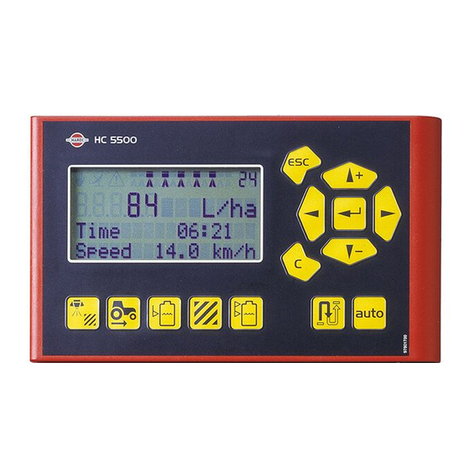
Hardi
Hardi HC 5500 SPRAY BOX III User manual

Hardi
Hardi HC5500 User manual

Hardi
Hardi HC5500 User manual
Hardi
Hardi HC 8500 User manual
Hardi
Hardi HC 6500 User manual
Hardi
Hardi HC 9600 User manual


