Tornatech LFX Manual

1
INSTALLATION AND MAINTENANCE MANUAL FOR
ELECTRIC FIRE PUMP CONTROLLERS
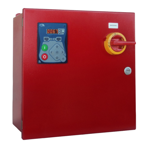
MODEL LFX

2
LFX-Manual-EN v1.1.0.0
1. Introduction
Table of Contents
2. Installation
3. Main Features
4. Alarms
5. Technical Documents

3
Table of Contents
Introduction......................................................................................................................................................................4
Types of Electric Fire Pump Controllers ....................................................................................................................4
Methods of Starting/Stopping.....................................................................................................................................4
Installation.......................................................................................................................................................................5
Location......................................................................................................................................................................5
Mounting ....................................................................................................................................................................5
Storage.......................................................................................................................................................................5
Wiring and Connections.............................................................................................................................................5
Electrical Wiring .........................................................................................................................................................5
Electrical Connections................................................................................................................................................5
Sizing..........................................................................................................................................................................5
Incoming Power Connections ....................................................................................................................................6
Motor Connections.....................................................................................................................................................6
Terminal Strip Descriptions........................................................................................................................................7
Quick Start-Up Guide.................................................................................................................................................8
Maintenance...............................................................................................................................................................9
Main Features ...............................................................................................................................................................10
Inputs........................................................................................................................................................................10
Outputs.....................................................................................................................................................................10
Alarms...........................................................................................................................................................................11
Alarms (Remote Alarm Panel) .................................................................................................................................11
Troubleshooting .......................................................................................................................................................11
Technical Documents....................................................................................................................................................12
Pre-Field Acceptance Test.......................................................................................................................................13
Field Acceptance Test Report..................................................................................................................................15

4
Electric fire pump controllers are designed to start an electric motor driven fire pump. It can either start the fire
pump manually through the local start pushbutton or automatically through the sensing of a pressure drop in the
sprinkler system. The fire pump can be stopped manually with the local stop pushbutton or automatically after the
restauration of the pressure in the sprinkler system. In both cases, stopping is only allowed if all starting causes
have disappeared.
Types of Electric Fire Pump Controllers
FIRE PUMP CATALOG NUMBER
MODEL No. EXAMPLE: LFY - 380 / 50KW / 3 / 50
Model Prefix: LFY
Voltage: 380 V
HP/KW Rating: 50 / 50KW
Phase: 3
Frequency: 50 Hz
ACROSS-THE-LINE STARTER
MODEL LFA:
This model is intended to be used where the local utility or the capacity of the power source permits across-
the-line starting.
Full voltage is applied to the motor as soon as the controller receives a start command.
REDUCED VOLTAGE STARTERS
These models are intended to be used where the local utility or the capacity of the power source does not permit full
voltage starting.
MODEL LFY: WYE-DELTA OPEN TRANSITION STARTER
This type of starter requires a multi-connection motor and 6 conductors between the controller and the
motor.
Upon a start command, the motor is connected to the line in the Wye connection. After a time delay, the
motor is reconnected to the line in the Delta configuration applying full voltage to the motor windings. This
controller is of the open transition type. The motor is disconnected from the line during the transition from
start (wye) to run (delta) mode.
Methods of Starting/Stopping
The controllers are available as combination automatic / non-automatic.
METHODS OF STARTING
AUTOMATIC START
The controller will start automatically on low pressure detection by the pressure switch when the pressure drops
below the cut-in threshold.
MANUAL START
The motor can be started by pressing the EMERGENCY START push button, regardless of the system pressure.
METHODS OF STOPPING
MANUAL STOP
Manual stop is done by pressing the priority STOP push button. Note that pressing the stop push button will
prevent the motor from restarting as long as the button is pressed.
Introduction

5
The LFX electric fire pump controller is intended to be installed in accordance with the Loss Prevention Standard
1237 Requirements for control panels for electric motor driven pumps used in automatic sprinkler installations and
the Local Electrical Codes.
Location
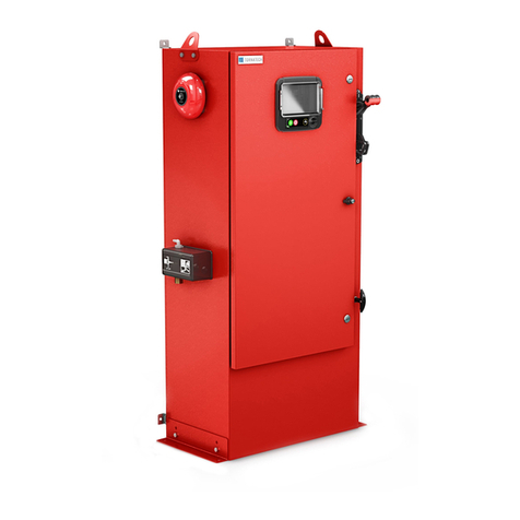
The controller shall be located as close as practical to the engine/motor it controls and shall be within sight of the
engine/motor. The controller shall be located or protected such that it will not be damaged by water escaping from
pump or pump connections. Current carrying parts of the controller shall be not less than 12 in. (305 mm) above the
floor level.
Working clearances around controller shall comply with local codes.
The controller is suitable for use in locations subject to a moderate degree of moisture, such as a damp basement.
The pump room ambient temperature shall be between 32°F (0°C) and 122°F (50°C).
The standard controller enclosure is rated IP55. It is the installer’s responsibility to insure that either the standard
enclosure meets the ambient conditions or that an enclosure with an appropriate rating has been provided.
Controllers must be installed inside a building and they are not designed for outside environment. The paint color
may change if the controller is exposed to ultraviolet rays for a long period of time.
Mounting
The fire pump controller shall be mounted in a substantial manner on a single incombustible supporting structure.
Wall mounted controllers shall be attached to the structure or wall using all four (4) mounting ears provided on the
controller with hardware designed to support the weight of the controller at a height not less than 12 in. (305 mm)
above floor level. Floor mounted controllers shall be attached to the floor using all holes provided on the mounting
feet with hardware designed to support the weight of the controller. The mounting feet provide the necessary 12 in.
(305 mm) clearance for current carrying parts.
Storage
If the controller is not installed and energized immediately, Tornatech recommend following the instructions from the
chapter 3 of the NEMA ICS 15 standard.
Wiring and Connections
Electrical Wiring
The electrical wiring between the power source and the fire pump controller shall meet the local codes. Electrical
wiring shall be typically sized to carry at least 125% of the full load current (FLC or FLA) of the fire pump motor.
Electrical Connections
A licensed electrician must supervise the electrical connections. The dimension drawings show the area suitable for
incoming power and motor connections. No other location shall be used. Only watertight hub fittings shall be used
when entering the cabinet to preserve the IP rating of the cabinet. The installer is responsible for adequate
protection of the fire pump controller components against metallic debris or drilling chips. Failure to do so may
cause injuries to personnel, damage the controller and subsequently void warranty.
Sizing
Incoming power terminals on the controller are suitable to accept wire based on that selection with insulation not
less than 60°C. (Refer to terminal diagram for terminal sizes.)
The electrical wiring between the fire pump controller and the pump motor shall be in rigid, intermediate, or liquid
tight flexible metal conduit or Type MI cable and meet the requirements of local codes.
Installation

6
The number of conductors required varies depending on the model of starter:
3-wires plus ground sized at 125% of full load current for model LFA.
6-wires plus ground sized at 125% of 58% of the motor full load current for model LFY.
Incoming Power Connections
Incoming normal power is to be connected to terminals identified L1 - L2 and L3 located on the disconnecting
means IS. The neutral wire is to be connected to the terminal reserved to this mean.
Motor Connections
The motor wires U1-V1-W1 (and U2-V2-W2 for LFY model) shall be connected to terminals identified by:
- U1-V1 and W1 are located on main contactor (1M) for model LFA.
- U1-V1 and W1 are located on contactor (1M) and U2-V2 and W2 are located on contactor (2M) for model LFY.
It is the responsibility of the installer to obtain connection information on the motor and to assure that the motor is
connected as per motor manufacturer recommendations. Failure to do so may cause injuries to personnel, damage
the motor and/or the controller and subsequently void warranty on both items.

7
Terminal Strip Descriptions
B-F: Alarms output terminals and pressure switch
(Pump Running)
B: Start Failure alarm
C: AC Phase Failure alarm
D: Pump Running alarm
E: Pump On Demand alarm
F: Pump Running pressure switch
Field input terminal:
G: Starting Pressure Switch (1-2-3)
Factory IO:
A: Lamps and pushbuttons connections
H: Starter Contactor Connections
I: Power inputs
J: Testing connector (factory use only)

8
Quick Start-Up Guide
The rating label is the most important label. It must be read carefully to ensure the compatibility between the
controller and the installation.
Verify that the controller is installed securely on the wall.

9
Make sure to drill holes for the motor and power connections and run the cables inside the panel, all in accordance
with the specifications in order to minimize interference with other equipment.
Connect the input power and the motor on their respective terminals. Secure with the appropriate torque as
indicated on the torque label and verify all connections. Secure the door in closed position then put the fuse
isolating switch disconnecting means in ON position.
Verify the motor rotation to ensure that the pump is turning in the right direction. The START and STOP push
buttons can be used to toggle the motor ON/OFF.
Maintenance
Periodically, do this procedure:
1- Verify that the “Main Supply Healthy” lamp is lit.
2- Press the lamp test button and verify that the other 3 lamps are working.
3- Open the plastic hinged cover on the “Emergency Start” pushbutton and press it.
4- Verify that the pump is starting and that the “Pump on Demand” lamp and “Pump Running” lamp are lit.
5- Let the pump run for 5 minutes, then press the “Stop/Reset” pushbutton.
6- Verify that the pump did stop.
7- Replace the cover on the Emergency Start button.

10
Inputs
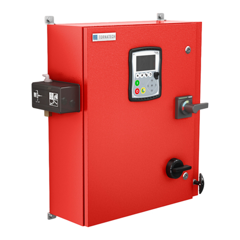
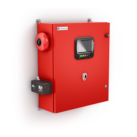
Buttons: This controller is equipped with 3 pushbuttons and an Isolation Switch on the outside of the door.
-Emergency Start (PB1-Green): This button is used to open the sensing circuit and trigger the start of the pump. It is
protected by a plastic cover and should be used only in case of a real fire.
-Stop/Reset (PB2-Red): This button is used to close the sensing circuit and stop the pump. If the demand is still
active, the pump will start again on the release of this button.
-Lamp Test (PB3-Black): This button is used to test 3 of the indication lights (Pump on demand, Start Failure and
Pump Running). The other light (Main Supply Healthy), can’t be tested with this button, but should always be active
if the controller is under power with 3 phases.
-Isolation Switch (IS): Used to power the controller and the pump by closing or opening the 3 phases. It is not
possible to open the controller door without turning OFF the Isolation Switch.
Ammeter: A current transformer on L2 and a display on the controller door enable the user to monitor the Ampere
consumption on one phase.
Pressure Switches (PS1-PS2-PS3): This controller can be equipped with 3 pressure switches. These switches will
open the starting circuit on a pressure drop and activate the starting of the pump. Connect PS1 between 1-1A, PS2
between 1A-1B and PS3 between 1B-2. If one of these switches is not used or removed, place a jumper between
the corresponding connecting points.
Pressure Switch (PS4): This switch is intended to be installed at the pump discharge. The switch contact will open
at low pressure when the pump is not running and trigger the “Start Failure” alarm. At working pressure this switch
will close. Install this switch between 40-41 input on the relay board.
Outputs
Lamps: This controller is equipped with 4 lights to indicate the state of the controller and the pump.
-AC Supply Healthy (Green): This light indicates that the main power is healthy on all 3 phases and that the control
supply is available.
-Pump on Demand (Green): This light indicates that a demand signal is active from either the Emergency Start
button or from a Pressure Switch. The motor should be either starting or running.
-Pump Running (Green): This light indicates that the motor is running.
-Start Failure (Red): This light indicates that the pump is powered but that the discharge pressure is low.
Alarms: See Alarm section for more details
Main Features

11
Alarms (Remote Alarm Panel)
The LFX control panel provides four alarm light. Those alarms are also four output signals on the relay board that
can activate alarms on a remote panel.
- Pump On Demand: Activates when a pressure switch’s contact on the sprinkler system is open by a drop of
pressure or when the Emergency Start button is pushed. The pressure switch’s contact open at low pressure.
- Pump Running: Activates when the contact of the pressure switch on the pump discharge closes. This pressure
switch contacts open at low pressure.
- AC Failure: Activates when either one of the three phases is unpowered.
- Start Failure: Activates when the starter contactors are in the final position and the pressure switch on the pump
discharge is open (low pressure).
Troubleshooting
For any unusual behavior of the controller panel, please contact the manufacturer.
Alarms

12
Patents
Country
Title
Grant No
CA
Mechanical activator for contactor
2741881
US
Mechanical activator for contactor
US8399788B2
CA
Mechanical activator for electrical contactor
165512
CA
Mechanical activator for electrical contactor
165514
US
Mechanical activator for electrical contactor
D803794
US
Mechanical activator for electrical contactor
Patent pending
EP
Mechanical activator for electrical contactor
002955393-
0001/2
AE
Mechanical activator for electrical contactor
Patent pending
AE
Mechanical activator for electrical contactor
Patent pending
CA
Fire pump digital operator
163254
US
Fire pump digital operator interface
D770313
AE
Fire pump digital operator interface
Patent pending
EP
Fire pump digital operator interface
002937250-0001
CA
System and method for detecting failure in a pressure sensor of a fire pump system
Patent pending
US
System and method for detecting failure of a pressure sensor in a fire pump system
Patent pending
Technical Documents

13
Pre-Field Acceptance Test
TORNATECH MODEL LFX
ELECTRIC FIRE PUMP CONTROLLER
PRE- FIELD ACCEPTANCE TEST
CHECK LIST
Note: This document should be an official indication of whether or not the installation and general
condition of the equipment is adequate for a field acceptance test. This document should also aid the
individual responsible for executing the field acceptance test to decide whether or not to carry out the field
acceptance test of the equipment.
Installation Check List:
YES
NO
1
Verify that the nameplate of the Fire Pump Controller corresponds with the AC voltage
available.
2
Procede to a visual inspection for any damage done to the exterior of the Fire Pump
Controller. Make sure the enclosure, the indication lamps and the pushbuttons are not
damaged.
3
Verify that the Fire Pump Controller has been installed within sight of the pump and
engine or motor.
4
Verify that the Fire Pump Controller has been installed not less than 12 inches from the
floor of the mechanical room.
5
Verify that all electrical connections to the Fire Pump Controller are done using liquid
tight conduit and connectors.
6
With the Fire Pump Controller door open, visually inspect for any drill chips, dirt or
foreign objects in the bottom of the enclosure, loose wires, broken components and
general proper electrician workmanship.
7
Verify that the correct Normal Power AC voltage is supplied to the controller by taking a
voltage reading at the incoming terminals of the isolating switch (IS).
8
Verify that the motor leads are connected for the corresponding starting method.
Initial Power-Up Check List:
YES
NO
1
Controller door must be closed and latched, with Disconnecting Means handle in the
OFF position.
2
Verify that the Normal Power voltage and hertz displayed on the rating label are the
same as measured in point 7 of the Installation Checklist above.
Note: A manual or automatic start must only be executed if the motor and the pump
have been cleared to be started by their respective official service technicians.
YES
NO
1
Place the Disconnecting Means handle in the ON position.
2
Press the EMERGENCY START pushbutton. The motor will start.
3
Verify the motor rotation:
• If the motor rotation is correct, no adjustment is required.
• To correct the motor rotation, change the motor connection leads U1 with W1 (and V2
with W2 for LFY model) at the run contactor M1 (and M2 for LFY model)
4
Verify any alarms that would appear on the remote alarm panel. Correct any alarm
condition.
5
Verify the automatic start by dropping the system pressure.
6
Stop the motor by pressing the “stop” button. Note: the motor will stop whether or not
the demand is still active. If the demand is still active, the motor will restart upon
release of the pushbutton.

14
Tornatech Controller S/N: _________________________________________
Installation address: _________________________________________
_________________________________________
_________________________________________
Check list completed? _____________Yes _____________ No
Check list completed by: __________________________________________
Company: __________________________________________
Date: __________________________________________
Witnessed By: __________________________________________
Comments: ___________________________________________________________________________
___________________________________________________________________________
___________________________________________________________________________
___________________________________________________________________________
___________________________________________________________________________
___________________________________________________________________________

15
Field Acceptance Test Report
TORNATECH MODEL LFX
ELECTRIC FIRE PUMP CONTROLLER
FIELD ACCEPTANCE TEST REPORT
Complete this first section if it was not completed during the Pre-Field Acceptance test
Note: A manual or automatic start must only be executed if the motor and the pump
have been cleared to be started by their respective official service technicians.
YES
NO
1
Place the Disconnecting Means handle in the ON position.
2
Press the EMERGENCY START pushbutton. The motor will start.
3
Verify the motor rotation:
• If the motor rotation is correct, no adjustment is required.
• To correct the motor rotation, change the motor connection leads U1 with W1 (and
V2 with W2 for LFY model) at the run contactor M1 (and M2 for LFY model)
4
Verify any alarms that would appear on the remote alarm panel. Correct any alarm
condition.
5
Verify the automatic start by dropping the system pressure.
6
Stop the motor by pressing the “stop” button. Note: the motor will stop whether or not
the demand is still active. If the demand is still active, the motor will restart upon
release of the pushbutton.
Motor Starts
Normal Power
YES
NO
1
6 manual starts
2
6 automatic starts
Field Settings:
Alarm Contacts Connections:
Fire Pump Controller
Motor Run connected? _____Yes _____ No
Pump On Demand connected? _____Yes _____ No
AC Failure connected? _____Yes _____ No
Start Failure connected? _____Yes _____ No
Other contacts supplied and connected?
Yes: ________________________________________________
No: _____
Tornatech Controller S/N: _________________________________________
Installation address: _________________________________________
_________________________________________
Field Acceptance Test completed? _____Yes _____ No
Field Acceptance completed by: __________________________________________
Company: __________________________________________
Date: __________________________________________

16
Witnessed By: __________________________________________
Company: __________________________________________
Comments: _____________________________________________________________________________
_____________________________________________________________________________
_____________________________________________________________________________
_____________________________________________________________________________
_____________________________________________________________________________

17
Table of contents
Other Tornatech Controllers manuals
