Tornatech VPX Manual

V2024.02
INSTALLATION AND MAINTENANCE MANUAL
FOR VARIABLE SPEED ELECTRIC FIRE PUMP
CONTROLLERS MODEL VPX+VPU

V2024.02 2
TABLE OF CONTENTS
Important Safety Information 4
Introduction 6
TechnicalData 6
Installation 7
Storage 7
Seismic 7
Environment 7
Electromagneticcompatibility(EMC) 7
Handling 7
FCCRegulationsandRadioStandardsSpecification(RSS)Rules 7
Location 8
Mounting 8
Floormounting 9
Wallmounting 9
MakingSystemPressureConnections 9
MakingElectricalConnections 9
ImportantPrecautions 10
Procedure 10
Operator interface 12
Methods of starting and stopping 13
VariableSpeedElectricFirePumpmodeswitch 13
VFDmode 13
Bypassmode 13
Methodsofstarting 13
Automaticstart 13
Manualstart 13
Remotemanualstart 13
Remoteautomaticstart,delugevalvestart 13
Emergencystart 13

V2024.02 3
Sequentialstart 14
Teststart 14
Methodsofstopping 14
Manualstop 14
Automaticstop 14
Emergencystop 14
Transfer switch operation sequence 15
Transfertoalternatepowersource 15
Re-transfertonormalpowersource 15
Testtransfersequence 15
Manualoperation 15
Commissioning 17
VFDReforming 17
procedure 17
VFDSettings 17
Graphicdisplayterminal 17
Motorparameters 17
Basicparameters 18
Autotune 18
Procedure 19
Maintenance 20
Patents 21

V2024.02 4
IMPORTANT SAFETY INFORMATION
Warning:
This product can expose you to chemicals including DINP, which is known to the State of Cali-
fornia to cause cancer, and DIDP which is known to the State of California to cause birth
defects or other reproductive harm.
Warning:
This product can expose you to chemicals including lead and lead compounds, which are
know to the State of California to cause cancer and birth defects or other reproductive harm.
Formoreinformationgoto:www.P65Warnings.ca.gov
DANGER
RISK OF ELECTROCUTION
PERSONAL INJURY OR DEATH COULD OCCUR.
ENSURE ALL POWER IS DISCONNECTED BEFORE INSTALLING OR SERVICING
THIS EQUIPMENT.

V2024.02 5
DANGER
Do not attempt to install or perform maintenance on equipment while it is energized! Death,
personal injury or substantial property damage may result from contact with energized equip-
ment. Always verify that no voltage is present before proceeding and always follow generally
accepted safety procedures. Controller disconnect switch must be in the “off” position in
order to open the enclosure door. Tornatech cannot be liable for any misapplication or incor-
rect installation of its products.

V2024.02 6
INTRODUCTION
VariableSpeedElectricFirePumpcontrollersaredesignedtostartanelectricmotordrivenfirepump.It
isequippedwithaVariableFrequencyDrive(VFD)thatwillregulatethemotorspeed,bycontrollingthe
frequencyappliedtothemotor,inordertomaintainacertainset-pointpressure.Itcaneitherstartthe
firepumpmanuallythroughthelocalstartpushbuttonorautomaticallythroughthesensingofapres-
suredropinthesprinklersystem.Thefirepumpcontrollerissuppliedwithapressuretransducer.The
firepumpcanbestoppedmanuallywiththelocalstoppushbuttonorautomaticallyaftertheexpiration
ofafieldprogrammabletimer.
Itisequippedwithanautomatictransferswitchthatfeedsthecontrollerfromeitherthenormalorthe
alternatepowersource.
TECHNICAL DATA
Rating Value
RatedOperationalCurrentIe AccordingtotheMotor(HP/kW)
RatedOperationalVoltageUe Accordingtothecontrollerratinglabel
RatedOperationalFrequency 50/60Hz
Standardenvironmentaltemperature 4°Cto40°C
Altitude ≤2000m
Relativehumidity 5%to80%
Pollutiondegree 3
ShortCircuitCurrentRatingIcc(SCCR)(A) Accordingtothecontrollerratinglabel
Standarddegreeofprotection NEMAType12
Standbypowerconsumption 200W

V2024.02 7
INSTALLATION
STORAGE
Ifthecontrollerisnotinstalledandenergizedimmediately,Tornatechrecommendsfollowingthe
instructionsinchapter3ofNEMAICS15.
SEISMIC
VariableSpeedElectricFirePumpcontrollersareoptionallyseismicapprovedandhasbeentestedin
accordancewiththeICC-ESAC156,IBC2015&CBC2013standards.Properinstallation,anchoringand
mountingisrequiredtovalidatethiscompliancereport.Refertothismanualanddrawingstodetermine
theseismicmountingrequirementsandlocationofthecenterofgravity(youmayneedtocontactfact-
ory).Theequipmentmanufacturerisnotresponsibleforthespecificationandperformanceofanchor-
agesystems.Thestructuralengineerofrecordontheprojectshallberesponsibleforanchoragedetails.
Theequipmentinstallationcontractorshallberesponsibleforensuringtherequirementsspecifiedby
thestructuralengineerofrecordaresatisfied.Ifdetailedseismicinstallationcalculationsarerequired,
pleasecontactthemanufacturerfortheperformanceofthiswork.
ENVIRONMENT
VariableSpeedElectricFirePumpcontrollersareintendedtobeinstalledinlocationswhereambient
temperaturesarewithin4°Cand40°Candtherelativehumidityiscontrolledbetween5%and80%.
Theyareintendedforpollutiondegree3andshallbeinstalledatanaltitudeofnomorethan2000
meters.Forabnormalinstallationenvironment,consultfactory.
ELECTROMAGNETIC COMPATIBILITY (EMC)
VariableSpeedElectricFirePumpcontrollershavebeentestedforthemoststringentconditionsfor
emissions(EnvironmentB)andimmunity(EnvironmentA),hencecontrollerscanbeinstalledineither
environment.Allcontrollersvariantssharethesameelectronicsandcomplytothosecriteriawithout
requiringadditionalmeasures.
HANDLING
TheweightofeachVariableSpeedElectricFirePumpcontrollerisindicatedonthepackinglabel.Light-
weightcontrollersdonotrequirespecialhandlinginstructions,whileheavycontrollersareequipped
withliftingmeansandshouldbehandledfollowingtheguidelinesspecifiedinTornatech'sdocument
"LargeEnclosureSafeHandlingRequirements_PN12162021".
FCC REGULATIONS AND RADIO STANDARDS SPECIFICATION
(RSS) RULES
TocomplywithFCCandIndustryCanadaRFexposurecompliancerequirements,aseparationdistance
ofatleast20cmmustbemaintainedbetweentheantennaofthisdeviceandallnearbypersons.This
devicemustnotbeco-locatedoroperatinginconjunctionwithanyotherantennaortransmitter.

V2024.02 8
Thisdevicecontainslicence-exempttransmitter(s)/receiver(s)thatcomplywithInnovation,Scienceand
EconomicDevelopmentCanada’slicence-exemptRSS(s).Operationissubjecttothefollowingtwocon-
ditions:
1. Thisdevicemaynotcauseinterference.
2. Thisdevicemustacceptanyinterference,includinginterferencethatmaycauseundesiredoper-
ationofthedevice.
Compliance:CANICES-003(B)/NMB-003(B)
Thisdevicecomplieswithpart15oftheFCCRules.Operationissubjecttothefollowingtwoconditions:
(1)Thisdevicemaynotcauseharmfulinterference,and(2)thisdevicemustacceptanyinterference
received,includinginterferencethatmaycauseundesiredoperation.
Note:ThisequipmenthasbeentestedandfoundtocomplywiththelimitsforaClassAdigitaldevice,
pursuanttopart15oftheFCCRules.Theselimitsaredesignedtoprovidereasonableprotectionagainst
harmfulinterferencewhentheequipmentisoperatedinacommercialenvironment.Thisequipment
generates,uses,andcanradiateradiofrequencyenergyand,ifnotinstalledandusedinaccordance
withtheinstructionmanual,maycauseharmfulinterferencetoradiocommunications.Operationofthis
equipmentinaresidentialareaislikelytocauseharmfulinterferenceinwhichcasetheuserwillbe
requiredtocorrecttheinterferenceathisownexpense.
“Changesormodificationsnotexpresslyapprovedbythepartyresponsibleforcompliancecouldvoid
theuser'sauthoritytooperatetheequipment.”
LOCATION
Consult the appropriate job plans to determine the controller mounting location.
Thecontrollershallbelocatedascloseaspracticaltotheengineormotoritcontrolsandshallbewithin
sightoftheengineormotor.Thecontrollershallbelocatedorprotectedsuchthatitwillnotbedam-
agedbywaterescapingfrompumporpumpconnections.Currentcarryingpartsofthecontrollershall
benotlessthan12in.(305mm)abovethefloorlevel.
WorkingclearancesaroundcontrollershallcomplywithNFPA70,NationalElectricalCode,Article110or
C22.1,CanadianElectricalCode,Article26.302oranyapplicablelocalcodes.
ThestandardcontrollerenclosureisratedNEMAType12.Itistheinstaller’sresponsibilitytoinsurethat
eitherthestandardenclosuremeetstheambientconditionsorthatanenclosurewithanappropriate
ratinghasbeenprovided.Controllersmustbeinstalledinsideabuildingandtheyarenotdesignedfor
outsideenvironment.Thepaintcolormaychangeifthecontrollerisexposedtoultravioletraysfora
longperiodoftime.
MOUNTING
TheVariableSpeedElectricFirePumpcontrollershallbemountedinasubstantialmanneronasingle
incombustiblesupportingstructure.

V2024.02 9
FLOOR MOUNTING
Floormountedcontrollersshallbeattachedtothefloorusingallholesprovidedonthemountingfeet
withhardwaredesignedtosupporttheweightofthecontroller.Themountingfeetprovidetheneces-
sary12in.(305mm)clearanceforcurrentcarryingparts.
WALL MOUNTING
Refer to the controller dimension drawing for necessary mounting dimensions.
Thecontrolleriswallmountedbyusingatleastfour(4)wallanchors,2anchorsforthetopmounting
bracketsand2anchorsforthebottommountingbrackets.Thebracketsaredimensionallyonthesame
centerlineforeaseinmounting.Thereshouldbeaclearanceofatleast6inches(152mm)aroundthe
controllertoallowproperaircirculationaroundtheequipment.
1. Usingeitherthedimensionprintorbymeasuringthedistancebetweenthecenterlinesofthe
lowerbracketslots,transcribethisdimensionontothewall.Note:Thebottomedgeoftheenclos-
ureshouldbeaminimumof12”(305mm.)fromthefloorincasefloodingofthepumproom
occurs.
2. Drillandputanchorsintothewallforthelowermountingbrackets.
3. Markonthewall,thelocationoftheholesintheuppermountingbrackets.
4. Drillandputanchorsintowallfortheuppermountingbrackets.
5. Installboltsandwashersinloweranchors.
6. Alignholesinuppermountingbracketsandinstallboltsandwashersinanchors.
7. Shimanchorsasnecessarytoensurerearofenclosureisverticallevelandenclosureisnot
stressed.
8. Tightenallanchorbolts.
9. Checktobesureenclosuredooropenandclosesfreelyandthatenclosureislevel.
MAKING SYSTEM PRESSURE CONNECTIONS
Thecontrollerrequiresone(1)“SystemPressure”connectionfromthesystempipingtotheenclosure.
Theconnectionfitting,1/2”NPTmaleport,isprovidedontheleftexternalsideoftheenclosureforthis
purpose.RefertoNFPA20forcorrectfieldpipingprocedureofthesensinglinebetweenthepumping
systemandthecontroller.Ifadrainispresent,theconnectiontothedrainisataperedconnectionfor
plastictubing.
MAKING ELECTRICAL CONNECTIONS
TheelectricalwiringbetweenthepowersourceandthefirepumpcontrollershallmeettheNFPA20,
NFPA70NationalElectricalCodeArticle695orC22.1CanadianElectricalCode,Section32-200orany
applicablelocalcodes.Electricalwiringshallbetypicallysizedtocarryatleast125%ofthefullloadcur-
rent(FLCorFLA)ofthefirepumpmotor.

V2024.02 10
IMPORTANT PRECAUTIONS
Alicensedelectricianmustsupervisetheelectricalconnections.Thedimensiondrawingsshowthearea
suitableforincomingpowerandmotorconnections.Nootherlocationshallbeused.Onlywatertight
hubfittingsshallbeusedwhenenteringthecabinettopreservetheNEMAorIPratingofthecabinet.
The installer is responsible for adequate protection of the Variable Speed Electric Fire Pump
controller components against metallic debris or drilling chips. Failure to do so may cause
injuries to personnel, damage the controller and subsequently void warranty.
Priortomakinganyfieldconnections
1. Opendoorofenclosureandinspectinternalcomponentsandwiringforanysignsoffrayedor
loosewiresorothervisibledamage.
2. Verifythatthecontrollerinformationiswhatisrequiredontheproject:
1. Tornatechcatalognumber
2. Motorelectricalnameplateinformationmatchescontrollerratingforvoltage,frequency,
FLAandHP.
3. Project'selectricalcontractormustsupplyallnecessarywiringforfieldconnectionsinaccordance
withtheNationalElectricalCode,localelectricalcodeandanyotherauthorityhavingjurisdiction.
4. Refertotheappropriatefieldconnectiondrawingforwiringinformation.
PROCEDURE
Allfieldconnections,remotealarmfunctionsandACwiringarebroughtintotheenclosurethroughthe
toporbottomconduitentrancesasindicatedonthedimensionaldrawing.
Donotplaceconduitentrancesonthesidesoftheenclosureunlessaglandplateisprovided.
1. Usingahole(conduit)punch,createaholeintheenclosureforthesizeconduitbeingused.
2. Installnecessaryconduit.
3. Pullallwiresnecessaryforfieldconnections,remotealarmfunctions,ACpowerandallother
optionalfeatures.Bringenoughwireinsidetheenclosuretomakeupconnectionstotheappro-
priateline,loadandcontrolterminalblockpoints.Besuretoconsulttheappropriatefieldcon-
nectiondiagramforconnectionpointsandacceptablewiresize.Forproperwiresizing,referto
theNationalElectricalCode,NFPA70.
4. Makeallfieldconnectionstotheremotealarmfunctionsandanyotheroptionalfeatures.
5. Connectmotortocontrollerloadterminals.
6. FindnameplateonVariableSpeedElectricFirePumpmotorandmakenoteofitsfullloadamprat-
ing.
7. VerifyAClinevoltage,phaseandfrequencywiththecontrollerdataplateontheenclosuredoor
priortoconnecting.
8. ConnectACpower.

V2024.02 11
9. Checktoseethatallconnectionsarebothcorrectlywired(inaccordancewiththefieldcon-
nectiondiagram)andtight.
10. Closetheenclosuredoor.

V2024.02 12
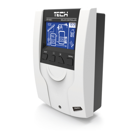
OPERATOR INTERFACE
A. StatusLED
B. Manualstart
C. Stop
D. Transfer-switchtest
E. Runtest
F. Alarmbuzzer
G. Touchscreendisplay
H. Factoryreserved
I. USBkeyconnectorforlogsdownloadandsoftwareupdates
J. EthernetconnectorforstandardTCP/IPcommunication

V2024.02 13
METHODS OF STARTING AND STOPPING
VARIABLE SPEED ELECTRIC FIRE PUMP MODE SWITCH
TheVPX+VPUisequippedwithaVFDmodeswitchthatislocatedundertheVizitouch.Itisprotectedby
alockablecover,andhas2positions;VFDandBYPASS.Ifthemodeswitchchangespositionwhilethe
motorisrunning,themotorwillstopandrestartinthenewmode
VFD MODE
Thisisthenormalmodeofoperation.ThecontrollerwillusetheVFDastheprimarystartingmeans,and
automaticallyswitchtothebypassstartingmeansincaseofaVFDalarm.Oncethecontrollerhasauto-
maticallyswitchedtothebypassstartingmeans,itwillremaininthisstateuntiltheVFDalarmsare
manuallyreset.
Note: When the motor is driven by the VFD, it may run at minimum speed when the system
pressure is above the set point pressure.
BYPASS MODE
Ifrequired,thebypassstartingmeanscanbemanuallyselectedusingthemodeswitch.
METHODS OF STARTING
AUTOMATIC START
Thecontrollerwillstartautomaticallyonlowpressuredetectionbythepressuresensorwhenthepres-
suredropsbelowthecut-inthreshold.
MANUAL START
Themotorcanbestartedbypressingthemanualstartpushbutton,regardlessofthesystempressure.
REMOTE MANUAL START
Themotorcanbestartedfromaremotelocationbymomentarilyclosingacontactofamanualpush-
button.
REMOTE AUTOMATIC START, DELUGE VALVE START
Themotorcanbestartedfromaremotelocationbymomentarilyopeningacontactconnectedtoan
automaticdevice.
EMERGENCY START
Themotorcanbestartedmanuallybyusingtheemergencyhandle.Thishandlecanbemaintainedina
closedposition.
Important: to avoid damaging the contactor, it is recommended to start the motor in this
manner:
1. Shutdownthemainpowerbyusingthemaindisconnectmeans,
2. Pulltheemergencystarthandleandlockitinclosedposition,
3. Turnthepowerbackonbyusingthemaindisconnectmeans.

V2024.02 14
SEQUENTIAL START
Incaseofamultiplepumpapplication,itmaybenecessarytodelaytheautomaticstartingofeach
motortopreventsimultaneousstartingofallmotors.
TEST START
Themotorcanbestartedintestmodemanuallybypressingtheruntestpushbutton,orautomatically
byusingtheperiodictestfeature.
METHODS OF STOPPING
MANUAL STOP
Manualstopisdonebypressingtheprioritystoppushbutton.Notethatpressingthestoppushbutton
willpreventthemotorfromrestartingaslongasthebuttonispressed,plusatwoseconddelay.This
actionhaspriorityoveranyactivedemand,butthemotorwillrestartautomaticallyoncethebuttonis
releasedifthereisany.
AUTOMATIC STOP
This function is never activated by default and must be authorized by the authority having
jurisdiction prior to activating.
Automaticstopispossibleonlyafteranautomaticstart.Whenthisfunctionisenabled,themotoris
automaticallystopped10minutesaftertherestorationofthepressuregiventhatnootherruncauseis
present.The10minutesdelayisadjustable.
EMERGENCY STOP
Theemergencystopisalwayspossibleinanystartingconditionandisdonebyusingthemaindis-
connectingmeanslocatedonthedoor.

V2024.02 15
TRANSFER SWITCH OPERATION SEQUENCE
Thetransfer-switchshallbesuppliedeitherbyasecondutilityorbyanon-sitestandbygeneratorcom-
plyingwiththerequirementsofaLevel1,Type10,ClassXsystemofNFPA110,meaningitshallsupply
powertothefirepumpcontrollerwithin10seconds.
Additionally,thefirepumpcontrollershallbefullyoperationalandreadytostartwithin10seconds
aftertheapplicationofpower.Thosetworequirementscombinedmeansthatthetotaltimeframe
betweenanormalpowerlossandathecontrollerbeingreadytostartonthealternatepower,if
providedbyagenerator,shallbeatmost20seconds.
TRANSFER TO ALTERNATE POWER SOURCE
Whenthenormalpowersourceisoutsideacceptableparametersforatleastthreeseconds,agenerator
startcommandisissued.Thethreeseconddelaycanbeadjustedtohelpmeetthe10secondsrequire-
mentofthegenerator,but doing so increases the risk of nuisance starting of the generatorincaseof
powerbrownouts.Specialconsiderationmustbetakenbeforeeditingthisvalue.
Oncethealternatepoweriswithinacceptableparametersforatleastanotherthreeseconds,thetrans-
fertothealternatepowersourceisinitiated.
RE-TRANSFER TO NORMAL POWER SOURCE
The transfer switch will stay in alternate position, if the motor is running, for as long as the
alternate power source is within acceptable parameters. The re-transfer sequence is enabled
if the motor is not running.
Whenthenormalpowersourceiswithinacceptableparametersforatleastfiveminutes,there-transfer
tothenormalpowersourceisinitiated.Acool-downperiodoffiveminutesmaintainsthegeneratorrun-
ningafterwhichitsstartcommandwillberemoved.
TEST TRANSFER SEQUENCE
Afulltransfersequencecanbeexecutedbymeansofpressingthetransfer-switchtestmembranebut-
ton.
MANUAL OPERATION
Thetransfer-switchisdesignedtobekeptinautomaticmodeatalltimes.Incertainemergencysitu-
ationsrequiringit,thetransfer-switchcanbemanuallyoperated.
Thereis180°betweentheNormalposition(I)andtheAlternateposition(II).Tooperatemanuallythe
TransferSwitch:
1. UsetheDisconnectSwitchestoturnOFFthepowerofbothNormalandAlternatesides.
2. OpenthedooroftheAlternateside.
3. OntheTransferSwitch,puttheselectorswitchinManualmode.
4. Takethehandle,situatedinsidethecontrollerdoorandinsertitinthesquareholeontheTrans-
ferSwitch.

V2024.02 16
5. Turnthehandleclockwise180°totransferfromAlternatetoNormalposition,orcoun-
terclockwise180°totransferfromNormaltoAlternateposition.
6. Removethehandleandputitbackonthesupportinsidethecontrollerdoor.
7. Ifrequired,pulltheemergencystarthandleandlockitinplace.
8. Closethedoorandusingthedisconnectingswitchhandlesputbackthepoweronbothsides.
BE CAREFUL
Do not close the controller door if the handle is still installed in the Transfer Switch.
Do not operate manually the Transfer Switch if the power is still ON.

V2024.02 17
COMMISSIONING
Only an authorized field acceptance provider shall proceed with Variable Speed Electric Fire
Pump controller commissioning. If you do not have the required training and authorization,
contact factory.
Untilcommissioningiscompleted,thecontrollermainscreenisreplacedbythecommissioningmenu
andtheautomaticmodeisdisabled.
VFD REFORMING
ReformingaVFDistheactionofapplyingvoltagetotheVFDpowerpathwithoutrunningamotor.Ifthe
drivewasnotconnectedtoavoltagesourceforanextendedperiodoftime,thecapacitorsmustbe
restoredtotheirfullperformancebeforethemotorisstarted,otherwisetheVFDmaybedamaged.
IftheVFDhasnotbeenstartedforayearormore,aVFD Reforming Requiredwarningwillbeissuedand
thecontrollerwillautomaticallystartinbypassuntilthereformingisdone.Propercontrollermain-
tenanceasperthisdocumentwillpreventreformingfrombeingrequiredundernormalconditions.
PROCEDURE
1. PlacethemodeswitchinVFD mode
2. Enteravalidlevel2password
3. FromtheVFD Configpage,presstheVFD Reformingbutton.
4. Waitforthereformingtocomplete
Note: The reforming operation will be interrupted if a starting request occurs, the mode
switch is changed, or the user cancel the operation. Only a full reforming procedure will reset
the VFD Reforming Required alarm.
Note 2: The reforming time is preset to 1 hour and is the required time for an inactivity
period of 1 year. For a greater inactivity period, consult factory for the proper reforming
time. An insufficient reforming time may lead to a damaged VFD .
VFD SETTINGS
GRAPHIC DISPLAY TERMINAL
TheVFDhasgraphicaldisplayterminalusedforconfiguringtheequipment.Itisnormallyattachedto
theVFDandcanberelocatedontheexterioroftheenclosureviatheprovideddoormountingkit.
Alwaysensurethatthedoormountingkitiseitherproperlyclosedorhasthedisplayproperlymounted
tomaintaintheNEMAType12ratingofthecontroller.
MOTOR PARAMETERS
OntheVFDgraphicdisplayterminal,gototheSimply StartMenu.Verifythatalltheinformationonthis
menuisthesameastheoneonthemotornameplate:

V2024.02 18
1. MotorStandard
1. 50Hz:ThenominalmotorpowerwillbeexpressedinKW
2. 60H:ThenominalmotorpowerwillbeexpressedinHP.
2. NominalMotorPower
3. NominalMotorVoltage
4. Nominalmotorcurrent
5. Nominalmotorfrequency
6. Nominalmotorspeed
7. Maxfrequency
Shouldbesettothenominalmotorfrequency.
BASIC PARAMETERS
ContinueontheSimplyStartmenuandmodifyorvalidatethenextparameters:
1. Accelerationramptime
2. Decelerationramptime
3. Lowspeed
4. Highspeed
RefertotheVFDParametersListforthefactorysettingsvalues.
AUTOTUNE
TheautotuneprocedureallowstheVFDtoacquireelectricalmotorcharacteristicsandenhancetheVFD
performance.Itisrecommendedtoperformtheautotuneonlyonceduringthefirststartup.
Performtheautotuneonastoppedandcoldmotorasheatcaninfluencethetuningresult.
WhiledoingtheAutotunetheVFDwillscanthemotorandacquireinformationaboutthemotor.
BeforestartingtheAutotuneontheVFD,readthewholeprocedure.Thenperformstepbystep.
1. PlacetheModeswitchontheVFDposition.
2. OntheVizitouch.Enteralevel2password.
3. GototheVFD ConfigpageandpresstheVFD Autotunebutton.TheVPxwillclosetheVFDisol-
atingcontactors.ThiswillenergizetheVFDpowerpathandallowittobeconnectedtothe
motor.TheVFDisolatingcontactorswillremainclosedfor3minutes.Duringthattime,youcan
performtheAutotuneontheVFDdisplay.
4. OntheVFDGraphicDisplayTerminal,gototheSimply Startmenu
5. GototheAutotuningparameterandpressOKtoentertheAutotuningpage.
6. SelectApply AutotuningandpressOK.

V2024.02 19
7. AWarningwillbedisplayedonscreen.PressOK.
8. Autotunewillbeperformed.YoucanvalidateitiscompletedbygoingontheSimply Startmenu
andassertthattheAutotuning StatusissettoAutotuning Done.
9. OntheVizitouch,presstheStopbuttonontheAutotunepopup.
Note: during this process, the motor might make small movements. Noise development and
oscillations of the system are normal. This may take for several seconds, do not interrupt the
process.
PROCEDURE
Tocommissionthecontroller:
1. SecurethedoorinclosedpositionthenputthecircuitbreakerdisconnectingmeansinONpos-
ition.
2. Loginwithyourpasswordandcompletethefirststartupmenuonthescreen.
3. MakesuretheprocedureiscompletedwiththeVFDsettoconstantspeedmode.
4. Forthree-phasemotors,incaseofincorrectrotationonthebypassstartingmeans,power off the
controllerandswaptwowiresatthecontactorloadside,thenpowerthecontrollerbackon.
5. IncaseofincorrectmotorrotationontheVFDstartingmeans,goonthegraphicaldisplayter-
minalandchangetheOutput phase rotationPHrparameterontheComplete settings > Motor
parameter > Motor Controlmenu.
6. Onceallthenecessarystepsarecompletedandthatyouareloggedinwithyourpassword,the
"ServiceDone"buttonwillbecomeonline.
7. Pressthe"ServiceDone"buttononceyouaresatisfiedwiththereadingsandparameters.
8. Downloadthelogstosaveinyourreport.
9. Tofinalizethecontrollercommissioning,itisimportanttorefertotheVPx Complete Setup pro-
ceduretoadjusttheadvancedparametersoftheVFD.ThiswillassuretheVFDresponsecorrectly
andinatimelymannertoapressuredrop.

V2024.02 20
MAINTENANCE
Tornatechcontrollersarecoveredbyalimitedwarrantyandbackedbya10-yearsservicelifeoruntil
supplylast,providedthatproperinstallation,commissioning,useandmaintenanceofthecontrolleris
madeasperthisdocument,NFPA25,andanymaintenancestandardapplicable.
Propercontrollerperformancemustbeassertedatleastonceamonthbyexecutingthefollowing:
1. Withthesystembeingatnominalpressure,ensurethatthepressurereadingiswithintolerances
2. PerformateststartsequenceonboththeVFDandthebypassstartingmeansandverifythat
1. Themotorstartswhenthepressurefallsbelowcut-in
2. Therearenoalarms
3. Thereisnonuisancetripping
4. Themotorstartsproperlyandisabletoacceleratewithintheexpectedtime
5. Themotorrotatesintheappropriatedirection
6. Thepumpisabletorisethepressureabovethecut-out
7. Themotorstopswhenthepressureisabovecut-outaftertheconfiguredtestduration
time
Inadditiontotheabove,thefollowingpreventativemaintenancemustbeperformedatleastonceyear:
1. Turnoffthecontroller
2. Doavisualinspectionoftheexteriorofthecontroller
3. Opentheenclosureanddoavisualinspectionoftheinteriorofthecontroller
4. Makesurethatthereisnodustaccumulationinsidethecontroller
5. Cleanthefansandairoutletfiltersfromdustaccumulation
6. Inspectthetightnessofeachdeadcable
7. Putthecontrollerbackinservice
This manual suits for next models
1
Table of contents
Other Tornatech Controllers manuals
