Toro 22910 User manual

Operator’s Manual
Original Instructions (EN)Register your product at www.Toro.com
Form No. 3353-857 Rev A
Vibratory Plow
for Compact Utility Loaders
Model No. 22910—200000001 & Up

2
W2005 by The Toro Company
8111 Lyndale Avenue South
Bloomington, MN 55420-1196
Contact us at www.Toro.com
All Rights Reserved
Printed in the USA
Contents
Page
Introduction 2. . . . . . . . . . . . . . . . . . . . . . . . . . . . . . . .
Safety 2. . . . . . . . . . . . . . . . . . . . . . . . . . . . . . . . . . . . .
Sound Pressure Level 3. . . . . . . . . . . . . . . . . . . . . .
Vibration Level 3. . . . . . . . . . . . . . . . . . . . . . . . . .
Safety Decals 4. . . . . . . . . . . . . . . . . . . . . . . . . . . .
Specifications 4. . . . . . . . . . . . . . . . . . . . . . . . . . . . . . .
Stability Ratings 4. . . . . . . . . . . . . . . . . . . . . . . . . .
Installation 5. . . . . . . . . . . . . . . . . . . . . . . . . . . . . . . . .
Installing a Blade 5. . . . . . . . . . . . . . . . . . . . . . . . .
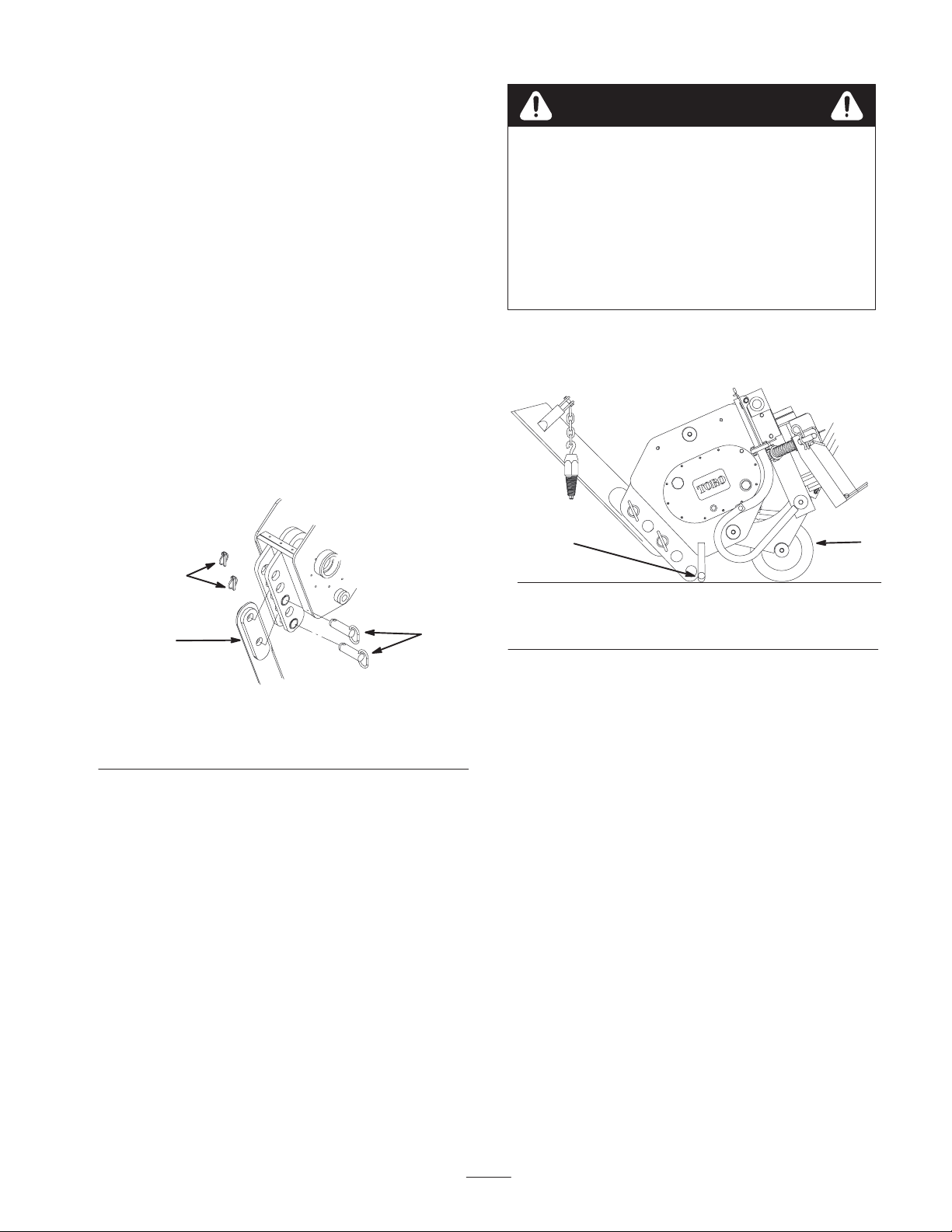
Removing the Plow from the Traction Unit 5. . . .
Operation 6. . . . . . . . . . . . . . . . . . . . . . . . . . . . . . . . . .
Plowing 6. . . . . . . . . . . . . . . . . . . . . . . . . . . . . . . .
Transporting the Plow 6. . . . . . . . . . . . . . . . . . . . .
Gauging Plow Depth 7. . . . . . . . . . . . . . . . . . . . . .
Tips for Plowing 7. . . . . . . . . . . . . . . . . . . . . . . . . .
Maintenance 8. . . . . . . . . . . . . . . . . . . . . . . . . . . . . . . .
Service Interval Chart 8. . . . . . . . . . . . . . . . . . . . .
Greasing 8. . . . . . . . . . . . . . . . . . . . . . . . . . . . . . . .
Lubrication 9. . . . . . . . . . . . . . . . . . . . . . . . . . . . . .
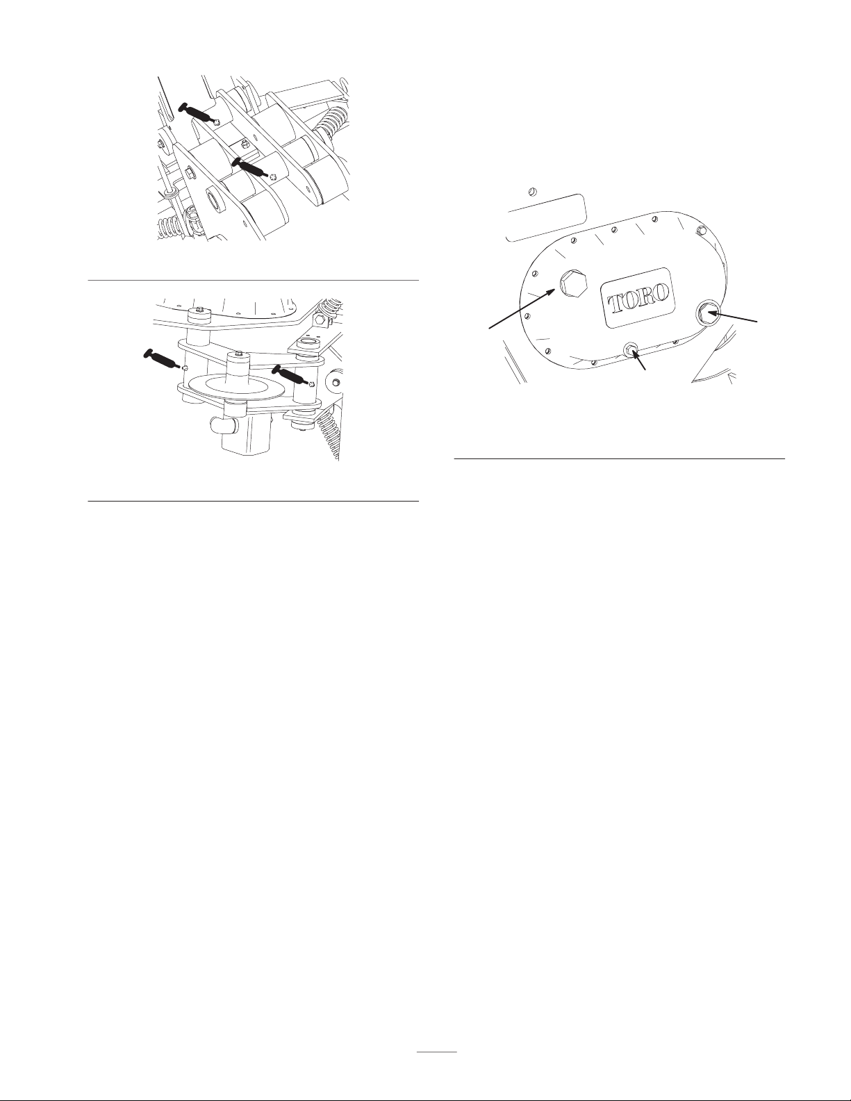
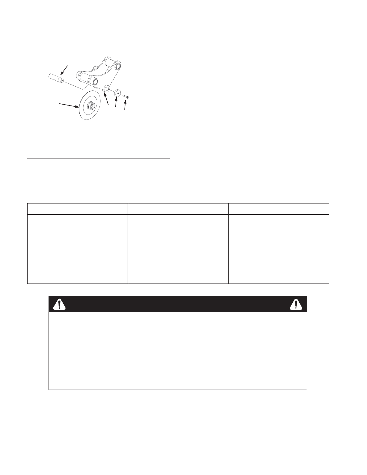
Replacing the Coulter 9. . . . . . . . . . . . . . . . . . . . .
Storage 10. . . . . . . . . . . . . . . . . . . . . . . . . . . . . . . . .
Troubleshooting 10. . . . . . . . . . . . . . . . . . . . . . . . . . . . .
Introduction
We want you to be completely satisfied with your new
product, so feel free to contact your local Authorized
Service Dealer for help with service, genuine replacement
parts, or other information you may require.
Whenever you contact your Authorized Service Dealer or
the factory, always know the model and serial numbers of
your product. These numbers will help the Service Dealer
or Service Representative provide exact information about
your specific product. You will find the model and serial
number on a plate located on the attachment receiver
plate. For your convenience, write the product model and
serial numbers in the space below.
Model No:
Serial No.
The warning system in this manual identifies potential
hazards and has special safety messages that help you and
others avoid personal injury, even death. DANGER,
WARNING and CAUTION are signal words used to
identify the level of hazard. However, regardless of the
hazard, be extremely careful.
DANGER signals an extreme hazard that will cause
serious injury or death if the recommended precautions
are not followed.
WARNING signals a hazard that may cause serious injury
or death if the recommended precautions are not followed.
CAUTION signals a hazard that may cause minor or
moderate injury if the recommended precautions are not
followed.
Two other words are also used to highlight information.
“Important” calls attention to special mechanical
information and “Note” emphasizes general information
worthy of special attention.
The left and right side of the machine is determined by
standing in the normal operator’s position.
Safety
Improper use or maintenance by the operator or owner
can result in injury. To reduce the potential for injury,
comply with the safety instructions in the traction unit
operator’s manual and always pay attention to the
safety alert symbol, which means CAUTION,
WARNING, or DANGER—“personal safety
instruction.” Failure to comply with the instruction
may result in personal injury or death.
DANGER
POTENTIAL HAZARD
•There may be buried power, gas, and/or
telephone lines in the area being plowed.
WHAT CAN HAPPEN
•Shock or explosion may occur.
HOW TO AVOID THE HAZARD
•Have the area to be plowed marked for buried
lines and do not plow in marked areas.
DANGER
POTENTIAL HAZARD
•Contact with moving plow may cause injury.
WHAT CAN HAPPEN
•The moving plow can cut hands, feet, or other
body parts.
HOW TO AVOID THE HAZARD
•Keep your hands, feet, and any other part of
your body or clothing away from moving parts.
•Before adjusting, cleaning, repairing, and
inspecting the plow, lower it to the ground, stop
the engine, remove the key, and wait for all
moving parts to stop.

3
WARNING
POTENTIAL HAZARD
•If you do not fully seat the attachment locking
pins in the attachment mount plate holes, the
attachment could fall off of the traction unit.
WHAT CAN HAPPEN
•The attachment could fall rearward onto the
operator, severely injuring him or her.
•Bystanders may be severely injured by the
attachment as it falls.
HOW TO AVOID THE HAZARD
•Ensure that you fully seat the attachment
locking pins through the holes in the
attachment mount plate before lifting the
attachment.
•Ensure that the attachment mount plate is free
of any dirt or debris that may hinder the
connection of the traction unit to the
attachment.
•Refer to your traction unit Operator’s Manual
for detailed information on safely connecting an
attachment to your traction unit.
WARNING
POTENTIAL HAZARD
•When the engine is off, attachments in the
raised position can gradually lower.
WHAT CAN HAPPEN
•Someone nearby may be pinned or injured by
the attachment as it lowers.
HOW TO AVOID THE HAZARD
•Always lower the attachment lift each time you
shut off the traction unit.
WARNING
POTENTIAL HAZARD
•The plow is very loud during operation.
WHAT CAN HAPPEN
•Over time, your hearing may be impaired if
unprotected.
HOW TO AVOID THE HAZARD
•Wear hearing protection during operation.
WARNING
POTENTIAL HAZARD
•When the plow is out of the ground, bystanders
could be injured by the swinging plow.
•The traction unit could be overturned by the
inertia of the swinging plow.
WHAT CAN HAPPEN
•You or bystanders could be crushed by the
traction unit or plow.
HOW TO AVOID THE HAZARD
•Keep the plow low at all times.
•Use caution when turning and do not turn
quickly.
•Keep all bystanders at least 6 ft. (2 meters)
away while operating.
CAUTION
POTENTIAL HAZARD
•Hydraulic couplers, hydraulic lines/valves, and
hydraulic fluid may be hot.
WHAT CAN HAPPEN
•Contact with hot hydraulic components or fluid
may cause burns.
HOW TO AVOID THE HAZARD
•Wear gloves when operating the hydraulic
couplers.
•Allow the traction unit to cool before touching
hydraulic components.
•Do not touch hydraulic fluid spills.
Sound Pressure Level
This unit has a maximum sound pressure at the operator’s
ear of 117 dB(A), based on measurements when operated
on a traction unit per Directive 81/1051/EEC. The sound
pressure level will vary depending on conditions.
Vibration Level
This unit has a maximum hand-arm vibration level of
7 m/sand whole body vibration level of 0.2 m/s
based on measurements of identical machines per EN
1033 and EN 1032.

4
Safety Decals
# 100–4650
3
6
4
6
# 100–4649
5
12
Figure 1
1. Explosion hazard
2. Shock hazard
3. Pinching/crushing
hazard—hand
4. Pinching/crushing
hazard—foot
5. Do not dig in areas with
underground utility lines
6. Keep bystanders away
Specifications
Note: Specifications and design are subject to change
without notice.
Width 29 inches (73.6 cm)
Length 35 inches (89 cm)
Height 24 inches (60 cm)
Weight (without blade) 400 lbs (181.5 Kg)
Hydraulic motor
displacement
1.27 in3/rev (20.8 cc)
Plow cycles 1,528 VPM
Stability Ratings
To determine the maximum degree of slope you can
traverse with the plow installed on a traction unit, find the
stability rating for the hill orientation you want to travel in
the table below, then find the degree of slope for the same
rating and orientation in the Stability Data section of the
traction unit operator’s manual.
Orientation Stability Rating
Front Uphill C
Rear Uphill D
Side Uphill C
IMPORTANT: If your traction unit has a rear
operator’s platform, the counterweight must be used
on the platform while using the plow, or the traction
unit will become unstable.
WARNING
POTENTIAL HAZARD
•Exceeding the maximum recommended slope
can cause the traction unit to tip.
WHAT CAN HAPPEN
•If the traction unit tips, you or bystanders could
be crushed.
HOW TO AVOID THE HAZARD
•Do not drive the traction unit on a slope steeper
than the maximum recommended slope, as
determined in the previous table and the
traction unit operator’s manual.

5
Installation
Refer to your traction unit Operator’s Manual for
complete instructions on installing attachments onto the
traction unit and connecting hydraulic hoses.
Installing a Blade
Toro offers several different blades and pullers. Purchase
a blade and puller from your Toro dealer.
1. Raise the plow about 36 in. (1 m) off of the ground
and install the cylinder locks.
2. Stop the engine and remove the key.
3. Remove the two click pins from the clevis pins in the
blade bracket, then remove the clevis pins (Fig. 2).
4. Slide the blade into the blade bracket and secure it at
the desired depth (a change in mounting holes will
change the depth by 3 in. (7.6 cm)), using the clevis
pins and click pins removed previously (Fig. 2).
m–4155
3
1
2
Figure 2
1. Click pin
2. Clevis pin
3. Blade
Removing the Plow from the
Traction Unit
Refer to your traction unit operator’s manual for complete
instructions on removing attachments from the traction
unit and disconnecting hydraulic hoses.
1. With the plow raised above the ground, stop the
engine.
2. Remove the lower click pin and clevis pin securing the
blade to the plow (to completely remove the blade,
remove both the upper and lower click and clevis pins)
(Fig. 2).
3. Swing the blade up and secure it as illustrated in
Figure 3.
CAUTION
POTENTIAL HAZARD
•The blade is sharp and has pinch points.
WHAT CAN HAPPEN
•The blade can swing and pinch or crush hands
or feet.
HOW TO AVOID THE HAZARD
•Wear gloves and work boots and securely hold
the blade.
4. Tilt the plow forward and lower it to the ground or
trailer, with the stand and coulter supporting the
weight of the plow (Fig. 3).
12
m–4337
Figure 3
1. Stand 2. Coulter
5. Stop the engine and remove the plow as directed in
your traction unit operator’s manual.
This manual suits for next models
1
Table of contents
Other Toro Construction Equipment manuals

Toro
Toro 68004C User manual

Toro
Toro MMX-658H-S User manual

Toro
Toro TXL 2000 User manual

Toro
Toro Line Painter 1200 User manual

Toro
Toro MM-650E-S User manual

Toro
Toro PT-36PP User manual

Toro
Toro 68130 User manual

Toro
Toro Pro Sneak 365 User manual

Toro
Toro CM-658H-S User manual

Toro
Toro MMX-655H-S User manual