Toro 03731 User manual

FormNo.3407-884RevA
27-inchVerticutter
Reelmaster®7000-DCuttingUnit
ModelNo.03731—SerialNo.400000000andUp
Registeratwww.Toro.com.
OriginalInstructions(EN)*3407-884*A

WARNING
CALIFORNIA
Proposition65Warning
Thisproductcontainsachemicalorchemicals
knowntotheStateofCaliforniatocausecancer,
birthdefects,orreproductiveharm.
ThisproductcomplieswithallrelevantEuropeandirectives.
Fordetails,pleaseseetheDeclarationofIncorporation(DOI)
atthebackofthispublication.
Introduction
Theverticutterkitsaremountedonaride-onmachineand
isintendedtobeusedbyprofessional,hiredoperators
incommercialapplications.Itisprimarilydesignedfor
verticuttinggrassonwell-maintainedlawnsinparks,sports
elds,andoncommercialgrounds.
Readthisinformationcarefullytolearnhowtooperateand
maintainyourproductproperlyandtoavoidinjuryand
productdamage.Youareresponsibleforoperatingthe
productproperlyandsafely.
YoumaycontactTorodirectlyatwww .Toro.comforproduct
andaccessoryinformation,helpndingadealer,ortoregister
yourproduct.
Wheneveryouneedservice,genuineToroparts,oradditional
information,contactanAuthorizedServiceDealerorToro
CustomerServiceandhavethemodelandserialnumbersof
yourproductready.Figure1identiesthemodelandserial
numbersontheproduct.Writethenumbersinthespace
provided.
g196973
Figure1
1.Locationofthemodelandserialnumbers
ModelNo.
SerialNo.
Thismanualidentiespotentialhazardsandhassafety
messagesidentiedbythesafetyalertsymbol(Figure2),
whichsignalsahazardthatmaycauseseriousinjuryordeath
ifyoudonotfollowtherecommendedprecautions.
g000502
Figure2
1.Safetyalertsymbol
Thismanualuses2wordstohighlightinformation.
Importantcallsattentiontospecialmechanicalinformation
andNoteemphasizesgeneralinformationworthyofspecial
attention.
Contents
Safety...........................................................................3
SafetyandInstructionalDecals.................................3
Setup............................................................................4
1InspectingtheVerticutter.......................................5
2InstallingtheTransportRollers...............................5
3InstallingtheO-ringandtheGrease
Fitting................................................................5
4InstallingtheTurf-CompensationSpring..................6
5AdjustingtheBladeDepth.....................................7
6AdjustingtheRearGrassShield..............................7
7AdjustingtheRollerScrapers..................................8
8AdjustingtheTransportRollers...............................8
9MountingtheVerticutterReel.................................9
10AdjustingtheCutting-UnitSteering.......................9
11AdjustingtheTurf-CompensationSettings.............10
ProductOverview.........................................................11
Specications........................................................11
Operation....................................................................11
TrainingPeriod......................................................11
OperatingTips.......................................................11
Maintenance.................................................................12
LubricatingtheVerticutter.......................................12
RemovingtheVerticutterBladesfromthe
Shaft.................................................................12
InstallingtheVerticutterBlades................................13
ServicingtheRoller.................................................13
©2016—TheToro®Company
8111LyndaleAvenueSouth
Bloomington,MN554202
Contactusatwww.Toro.com.
PrintedintheUSA
AllRightsReserved

Safety
ThismachinehasbeendesignedinaccordancewithENISO
5395:2013.
Improperuseormaintenanceofthisequipmentcan
resultininjuryordeath.Toreducethepotentialfor
injuryordeath,complywiththefollowingsafety
instructions.
•Read,understand,andfollowallinstructionsinthe
tractionunitOperator’sManualbeforeoperatingthe
verticutters.
•Read,understand,andfollowallinstructionsinthis
Operator’sManualbeforeoperatingtheverticutters.
•Neverallowchildrentooperatethetractionunitorthe
verticutters.Donotallowadultstooperatethetraction
unitortheverticutterswithoutproperinstruction.Only
trainedoperatorswhohavereadthisOperator’sManual
shouldoperatetheverticutters.
•Neveroperatetheverticutterswhentired,ill,orunderthe
inuenceofdrugsoralcohol.
•Keepallshieldsandsafetydevicesinplace.Ifashield,a
safetydevice,oradecalisillegibleordamaged,repairor
replaceitbeforeresumingoperation.Also,tightenany
loosenuts,bolts,andscrewstoensurethattheverticutters
areinsafeoperatingcondition.
•Wearappropriateclothing,includingeyeprotection;
slip-resistant,substantialfootprotection;andhearing
protection.Tiebacklonghairanddonotwearjewelry.
•Removealldebrisorotherobjectsthatmightbepicked
upandthrownbythereelbladesofthecuttingunit.Keep
allbystandersawayfromtheworkingarea.
•Iftheverticutterbladesstrikeasolidobjectortheunit
vibratesabnormally,stopandshutofftheengine.Check
theverticutterfordamagedparts.Repairanydamage
beforestartingandoperatingtheverticutter.
•Parkthemachineonalevelsurface,lowerthecutting
unitstotheground,shutofftheengine,engagethe
parkingbrake,andremovethekeywheneveryouleave
themachineunattended.
•Besurethattheverticuttersareinsafeoperating
conditionbykeepingnuts,bolts,andscrewstight.
•Removethekeyfromtheswitchtopreventaccidental
startingoftheenginewhenservicing,adjusting,orstoring
themachine.
•Performonlythosemaintenanceinstructionsdescribedin
thismanual.Ifmajorrepairsareeverneededorassistance
isdesired,contactanAuthorizedToroDistributor.
•Toensureoptimumperformanceandcontinuedsafety
certicationofthemachine,useonlygenuineToro
replacementpartsandaccessories.Replacementparts
andaccessoriesmadebyothermanufacturerscouldbe
dangerous,andsuchusecouldvoidtheproductwarranty.
SafetyandInstructionalDecals
Safetydecalsandinstructionsareeasilyvisibletotheoperatorandarelocatednearanyareaofpotential
danger.Replaceanydecalthatisdamagedormissing.
decal93-6688
93-6688
1.Warning—readthe
instructionsbefore
servicingorperforming
maintenance.
2.Cuttinghazardofhandor
foot—shutofftheengine
andwaitformovingparts
tostop.
3

Setup
LooseParts
Usethechartbelowtoverifythatallpartshavebeenshipped.
ProcedureDescriptionQty.Use
1Verticutter1Inspecttheverticutter.
Transportrollerassembly2
2Cotterpin2Installthetransportrollers.
O-ring1
3Greasetting1InstalltheO-ringandthegreasetting.
Turf-compensationassembly1
Longbolt1
Carriagebolt2
Flangelocknut3
4
Flangenut1
Installtheturf-compensationspring
assembly.
5Nopartsrequired–Adjustthebladedepth.
6Nopartsrequired–Adjustthereargrassshield.
7Nopartsrequired–Adjusttherollerscrapers.
8Nopartsrequired–Adjustthetransportrollers.
9Nopartsrequired–Mounttheverticutterreel.
10Nopartsrequired–Adjustthecutting-unitsteering.
11Nopartsrequired–Adjusttheturf-compensationsettings.
MediaandAdditionalParts
DescriptionQty.Use
Operator'sManual1Reviewthematerialandsaveitinanappropriateplace.
Important:Withouttheseparts,totalsetupcannotbecompleted.
4

Note:Determinetheleftandrightsidesofthemachine
fromthenormaloperatingposition.
Note:Whenevertheverticutterhastobetippedtoexpose
theverticutterblades,usethekickstand(suppliedwith
tractionunit)(Figure3).
g195547
Figure3
1.Kickstand
1
InspectingtheVerticutter
Partsneededforthisprocedure:
1Verticutter
Procedure
Aftertheverticutterisremovedfromthebox,inspectthe
following:
1.Checkeachendofthereelforgrease.Greaseshould
bevisiblyevidentinthereelbearingsandintheinternal
splinesofthereelshaft.
2.Ensurethatallnutsandboltsaresecurelytightened.
3.Makesurethatthecarrierframesuspensionoperates
freelyanddoesnotbindwhenmovedbackandforth.
2
InstallingtheTransportRollers
Partsneededforthisprocedure:
2Transportrollerassembly
2Cotterpin
Procedure
1.Ifthecuttingunitsareinstalledonthetractionunit,
parkthemachineonalevelsurface,lowerthecutting
unitstotheground,shutofftheengine,engagethe
parkingbrake,andremovethekey.
2.Secureatransportrollerbrackettoeachsideplatepin
withacotterpin(Figure4).
g195548
Figure4
1.Transportrollerassembly2.Cotterpin
Note:Therollershouldbepositionedtotherearofthe
verticutter.
5
3
InstallingtheO-ringandthe
GreaseFitting
Partsneededforthisprocedure:
1O-ring
1Greasetting
Procedure
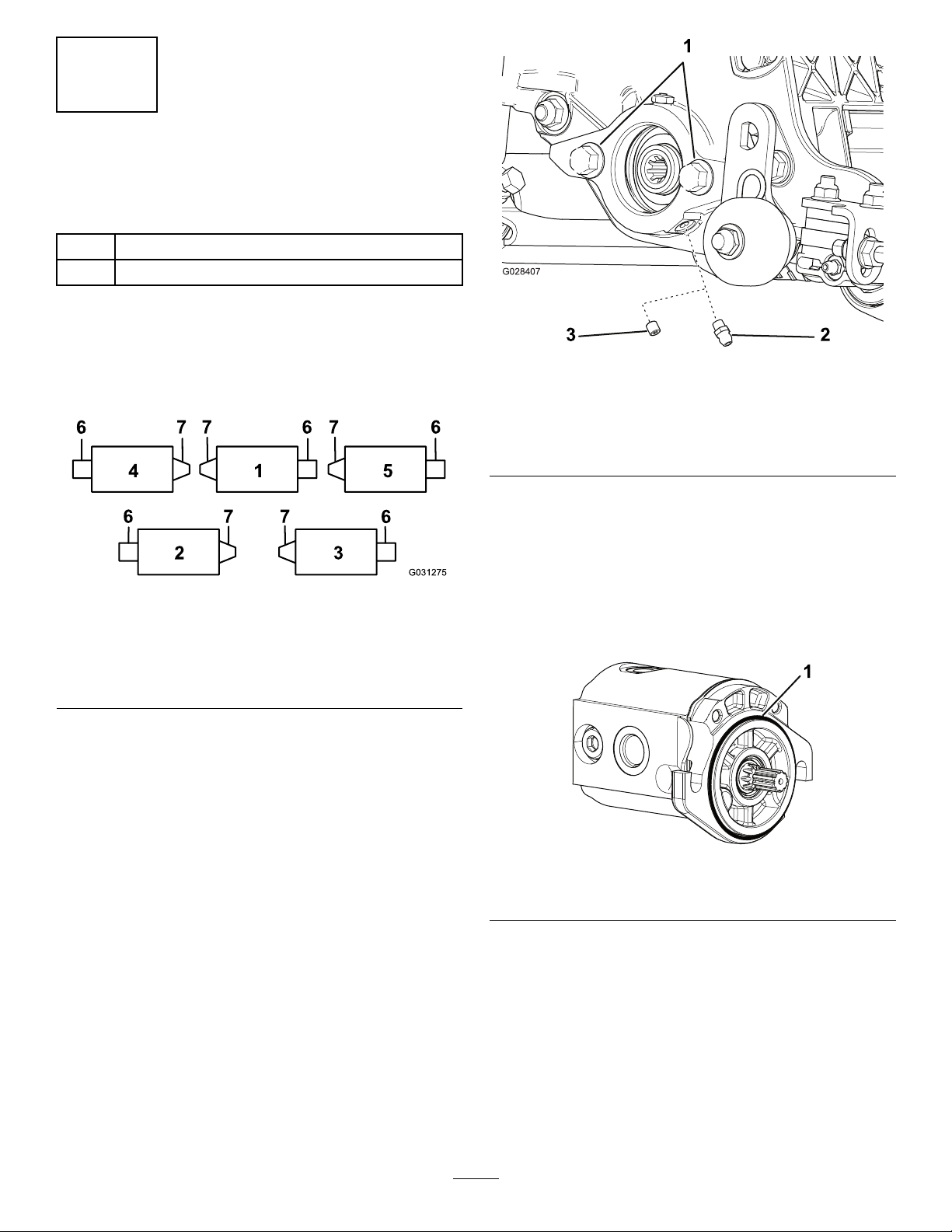
Thegreasettingmustbeinstalledonthereelmotorsideof
theverticutter.Usethefollowingdiagramtodeterminethe
positionofeachreelmotor(Figure5).
g031275
Figure5
1.Verticutter15.Verticutter5
2.Verticutter26.Reelmotor
3.Verticutter37.Weight
4.Verticutter4
1.Removeanddiscardthesetscrewonthereel-motor
sideplate(Figure6).
32
G028407
1
g028407
Figure6
1.Bolts3.Setscrew(removeand
discard)
2.Straightgreasetting
(install)
2.Installthestraightgreasetting(Figure6).
3.Forverticutter2andverticutter4locations(Figure
5),movetheendweighttotheoppositesideofthe
cuttingunit.
4.Iftherearenoboltsonthereel-motorsideplate,install
them(Figure6).
5.InstalltheO-ringonthereelmotor(Figure7).
g191072
Figure7
1.O-ring
6

4
Installingthe
Turf-CompensationSpring
Partsneededforthisprocedure:
1Turf-compensationassembly
1Longbolt
2Carriagebolt
3Flangelocknut
1Flangenut
Procedure
Installtheturfcompensationspringassemblyonthesame
sideasthereelmotor(Figure5andFigure8).
g196548
Figure8
1.Longbolt4.Flangelocknuts
2.Compensationspring
assembly
5.Flangenut
3.Carriagebolts
5
AdjustingtheBladeDepth
NoPartsRequired
Procedure
Note:Themaximumrecommendedbladepenetrationdepth
is6mm(1/4inch).
1.Placetheverticutterreelonalevelsurface.
2.Place2gaugebars,whichhavethedesireddepthof
bladepenetrationbelowtheground,underthefront
andrearrollersoftheverticutterreel(oneachendof
thereel)(Figure9).
g195549
Figure9
1.Gaugebar2.Adjustingbolt
Note:Theverticutterbladesmustnottouchthe
gaugebars.
3.Turntheadjustingboltoneachheight-of-cutbracket
(Figure9)sothatthereelbladescomeincontactwith
thelevelsurfaceonbothends.
Note:Astheverticutterbladeswear,thediameterof
thereelwilldecreaseandthedepthsettingwillchange.
Checkthedepthsettingperiodicallytoensurethatthe
desiredsettingisachieved.
7

6
AdjustingtheRearGrass
Shield
NoPartsRequired
Procedure
Note:Whenoperatinginturfconditionswheremuchdebris
orunusuallyheavythatchisencountered,opentherear
dischargeshieldtohelpallowthedebristodischargefrom
thereel.
1.Loosentheboltsonthepivotofthegrassshield
(Figure10).
g195550
Figure10
1.Pivotbolt2.Reargrassshield
2.Rotatethegrassshieldtothedesiredsetting,and
tightenthebolts(Figure10).
CAUTION
Throwndebriscouldcausepersonalinjury.
Donotopentherearshieldsothatitishigherthan
leveltoground.
7
AdjustingtheRollerScrapers
NoPartsRequired
Procedure
1.Loosentheangenutsthatsecuretherollerscrapers
(Figure11).
g195551
Figure11
1.Flangenuts3.Rearrollerscraper
2.Frontrollerscraper
2.Movethescraperrodsinorouttoattain0.0to0.75
mm(0.0to0.03inch)clearancebetweenthescraper
andtheroller.
3.Ensurethatthescraperrodisparalleltotherollerand
tothelevelsurface.
4.Tightentheangenutstolocktheadjustment.
8
AdjustingtheTransport
Rollers
NoPartsRequired
Procedure
Beforetheverticuttersareloweredtotheshopooror
removedfromthetractionunit,lowerthetransportrollers
(Figure11)toprotectthebladesfromhardsurfacecontact.
1.Removethecotterpinthatsecuresthetransportroller
brackettothesideplatepin.
2.Positionthetransportrollerasfollows:
•Lowertherollerbracketbeforetheverticutteris
loweredtotheshopoor.
•Raisetherollerbracketaftertheverticutterisraised
totheoperatingposition.
8

3.Securethetransportrollerbrackettothesideplatepin
withthecotterpin.
4.Repeattheprocedureontheoppositeendofthe
verticutter.
9
MountingtheVerticutterReel
NoPartsRequired
Procedure
Important:Whenloweringtheverticutterreels,care
mustbetakentopreventdamagetothereelbladesdue
tocontactwithaconcreteoororapavedsurface.Lower
thetransportrollersbeforeloweringtheverticuttiersto
aconcreteoororapavedsurface.
Figure12showstheorientationofthehydraulicdrivemotor
foreachofthelocations.
Verticutterreelsaremountedtothetractionunitthesame
waycuttingunitsare.RefertothetractionunitOperator's
Manualformountinginstructions.
g031275
Figure12
1.Verticutter15.Verticutter5
2.Verticutter26.Reelmotor
3.Verticutter37.Weight
4.Verticutter4
10
AdjustingtheCutting-Unit
Steering
NoPartsRequired
IncreasedSteeringfortheRearCutting
Units
Increasethesteeringontherearcuttingunitsbyremoving
the2pivotspacers,hexsocketscrews,andangelocknuts
(Figure13)fromthecarrierframesoftherearcuttingunits
(cuttingunits2and3);refertoFigure12.
1
2
3
4
G015978
g015978
Figure13
1.Hexsocketscrew3.Carrierframe
2.Pivotspacer4.Flangelocknut
LockingtheSteering
Tolock(x)thesteeringonthecuttingunits,securethepivot
yoketothecarrierframewiththesnapperpin(Figure14).
9

1
G015977
g015977
Figure14
1.Snapperpin
Note:Fixedsteeringisrecommendedwhencutting
sidehills.
11
Adjustingthe
Turf-CompensationSettings
NoPartsRequired
Procedure
Important:Makethespringadjustmentswiththe
cuttingunitmountedtothetractionunit,pointing
straightaheadandloweredtotheshopoor.
1.Makesurethatthehairpincotterisinstalledintherear
holeinthespringrod(Figure15).
g196971
Figure15
1.Hairpincotter3.Turf-compensationspring
2.Springrod4.Hexnuts
2.Tightenthehexnutsonthefrontendofthespringrod
untilthecompressedlengthofthespringis15.9cm
(6.25inches)(Figure15).
Note:Whenoperatingthemachineonroughterrain,
decreasethespringlengthby12.7mm(1/2inch).
Note:Theturf-compensationsettingwillneedtobe
resetiftheverticutterbladedepthsettingischanged.
10

ProductOverview
Specications
Netweight64kg(140lb)
Operation
Note:Determinetheleftandrightsidesofthemachine
fromthenormaloperatingposition.
TrainingPeriod
Beforeoperatingtheverticutterreels,evaluatethe
performanceofthereelatthedesiredsetting.Operateina
clear,unusedareatodeterminewhetherthedesiredresults
willbeachieved.Makeadjustmentsasnecessary.
OperatingTips
1.Operatethetractionunitatfullthrottle,fullreelspeed
(setting9)andatdesiredtractionspeed.
2.Themaximumrecommendedsettingis6mm(1/4
inch)deepbladepenetration.
3.Powerrequirementstooperatetheverticutterreelswill
varywithturfandsoilconditions.Travelspeedmay
needtobereducedinsomeconditions.
4.Whenoperatinginturfconditionswheremuchdebris
isencountered,orunusuallyheavythatch,openthe
frontandreardischargeshieldstohelpallowthedebris
todischargefromthereel.
CAUTION
Throwndebriscouldcausepersonalinjury.
Donotopentherearshieldsothatitishigher
thanleveltotheground.
11

Maintenance
LubricatingtheVerticutter
Eachverticutterhas5greasettings(Figure16)thatmustbe
lubricatedweeklywithNo.2lithiumgrease.
Thelubricationpointsarethefrontroller(2),therearroller
(2),andthereelmotorsplines(1).
Important:Lubricatingthecuttingunitsimmediately
afterwashinghelpspurgewateroutofthebearingsand
increasesbearinglife.
1.Wipeeachgreasettingwithacleanrag.
2.Applygreaseuntilyouseecleangreasecomingoutof
therollersealsandthebearingreliefvalve(Figure16).
g029271
Figure16
1.Reliefvalve
3.Wipeanyexcessgreaseaway.
RemovingtheVerticutter
BladesfromtheShaft
1.Securetheendoftheverticuttershaft,whichhasonly
onewasherandnut,inavise.
2.Onotherendofshaft,rotatethenutcounter-clockwise
andremovethenut.
CAUTION
Thebladesareextremelysharpandmayhave
burrsthatwillcutyourhands.
Usecautionwhenremovingthebladesfrom
theshaft.
3.Removethesmallspacer,thewasher,thebladesand
thelargespacers.Cleanandlubricatethesquareshaft
withalightcoatingofgreasetosimplifytheassembly
(Figure17).
g010889
Figure17
1.Shaft4.Smallspacer
2.Nut5.Blade(19)
3.Washer6.Largespacer(18)
Important:Donotinverttheverticutterreel
blades.Theorderofdisassemblyisextremely
important.Donotinverttheverticutterreel
bladeswhendisassemblingorreversetheorder
whenassemblingthem.Notetheverticutter
bladesindexhole.Theindexholeisprovidedfor
assemblyinordertoobtaintheproperhelixfor
theverticutterreel.
12

InstallingtheVerticutter
Blades
1.Assembleareelblade(Figure18).
2.Assemblealargespacer.
3.Donotinvertthereelbladeswhenreassemblingthem
ontothereelshaft.
Note:Ifthebladesareinverted,thebladesthatare
inuse(rounded)willbemixedwiththesharpends
ofthebladeswhichwerenotinuse.Thiswillcause
unsatisfactoryperformanceintheverticutterreelunit.
Paycloseattentionwhendisassemblingtheverticutter
bladesfromthereel.
4.Installthenextbladeclockwisesothattheindex
referencehole(Figure18)isnotalignedwiththerst
bladeholebyoneatoftheshaft.
g010890
Figure18
1.Indexreferencehole
5.Continuetoinstallspacersandbladesinthismanner
untilthefullcomplementofbladeshasbeeninstalled.
Note:Whenproperlyassembled,thebladeswillbe
staggeredinsuchamannerastoappearlikeahelix.
6.Installthesmallspacertotheshaft.
7.ApplyBlueLoctite242tothenut.Installthenutonto
theshaft,(withthemachinedsideofthenuttoward
thespacer)andtightenitto108.5to135N∙m(80to
100ft-lb).
ServicingtheRoller
ARollerRebuildKit,Part114-5430andaRollerRebuild
ToolKit,Part115-0803(Figure19)areavailableforservicing
theroller.TheRollerRebuildKitincludesallthebearings,
bearingnuts,innerseals,andoutersealstorebuildaroller.
TheRollerRebuildToolKitincludesallthetoolsandthe
installationinstructionsrequiredtorebuildarollerwiththe
rollerrebuildkit.Refertoyourpartscatalogorcontactyour
distributorforassistance.
13
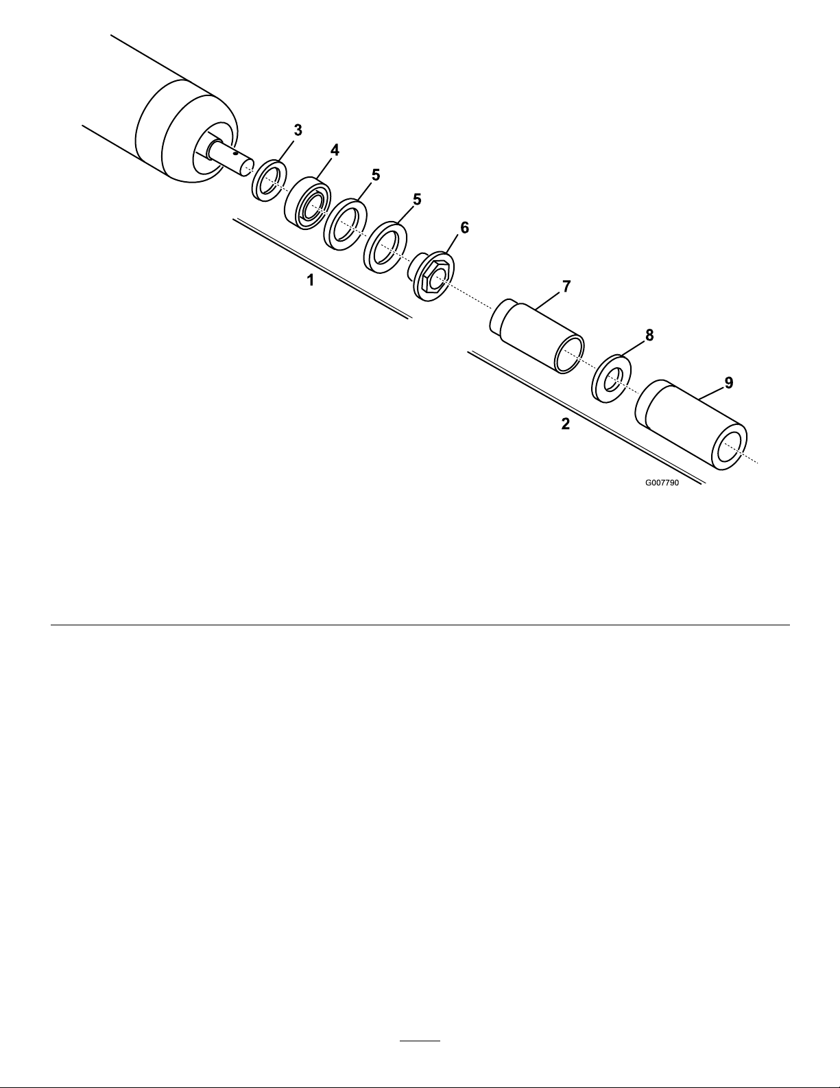
g007790
Figure19
1.Rebuildkit(PartNo.114–5430)6.Bearingnut
2.Rebuildtoolkit(PartNo.115–0803)7.Innersealtool
3.Innerseal8.Washer
4.Bearing9.Bearing/outersealtool
5.Outerseal
14

Notes:

Notes:

Notes:

DeclarationofIncorporation
TheT oroCompany,8111LyndaleAve.South,Bloomington,MN,USAdeclaresthatthefollowingunit(s)
conform(s)tothedirectiveslisted,wheninstalledinaccordancewiththeaccompanyinginstructionsontocertain
ToromodelsasindicatedontherelevantDeclarationsofConformity.
ModelNo.SerialNo.ProductDescriptionInvoiceDescriptionGeneralDescriptionDirective
03731400000000andUp
27-inchVerticutter,
Reelmaster7000-D
CuttingUnit
RM700027IN
VERTICUTTERCUVerticutter2006/42/EC
RelevanttechnicaldocumentationhasbeencompiledasrequiredperPartBofAnnexVIIof2006/42/EC.
Wewillundertaketotransmit,inresponsetorequestsbynationalauthorities,relevantinformationonthispartly
completedmachinery.Themethodoftransmissionshallbeelectronictransmittal.
ThismachineryshallnotbeputintoserviceuntilincorporatedintoapprovedT oromodelsasindicatedonthe
associatedDeclarationofConformityandinaccordancewithallinstructions,wherebyitcanbedeclaredin
conformitywithallrelevantDirectives.
Certied:EUT echnicalContact:
MarcelDutrieux
ManagerEuropeanProductIntegrity
ToroEuropeNV
Nijverheidsstraat5
2260Oevel
DavidKlisBelgium
Sr.EngineeringManager
8111LyndaleAve.SouthTel.+3216386659
Bloomington,MN55420,USA
November15,2016

EuropeanPrivacyNotice
TheInformationToroCollects
ToroWarrantyCompany(Toro)respectsyourprivacy.Inordertoprocessyourwarrantyclaimandcontactyouintheeventofaproductrecall,weaskyou
tosharecertainpersonalinformationwithus,eitherdirectlyorthroughyourlocalTorocompanyordealer.
TheT orowarrantysystemishostedonserverslocatedwithintheUnitedStateswhereprivacylawmaynotprovidethesameprotectionasapplies
inyourcountry.
BYSHARINGYOURPERSONALINFORMATIONWITHUS,YOUARECONSENTINGTOTHEPROCESSINGOFYOURPERSONALINFORMATION
ASDESCRIBEDINTHISPRIVACYNOTICE.
TheWayToroUsesInformation
Toromayuseyourpersonalinformationtoprocesswarrantyclaims,tocontactyouintheeventofaproductrecallandforanyotherpurposewhichwetell
youabout.T oromayshareyourinformationwithToro'safliates,dealersorotherbusinesspartnersinconnectionwithanyoftheseactivities.Wewillnot
sellyourpersonalinformationtoanyothercompany.Wereservetherighttodisclosepersonalinformationinordertocomplywithapplicablelawsand
withrequestsbytheappropriateauthorities,tooperateoursystemsproperlyorforourownprotectionorthatofotherusers.
RetentionofyourPersonalInformation
Wewillkeepyourpersonalinformationaslongasweneeditforthepurposesforwhichitwasoriginallycollectedorforotherlegitimatepurposes
(suchasregulatorycompliance),orasrequiredbyapplicablelaw.
Toro'sCommitmenttoSecurityofYourPersonalInformation
Wetakereasonableprecautionsinordertoprotectthesecurityofyourpersonalinformation.Wealsotakestepstomaintaintheaccuracyandcurrent
statusofpersonalinformation.
AccessandCorrectionofyourPersonalInformation
Ifyouwouldliketorevieworcorrectyourpersonalinformation,pleasecontactusbyemailat[email protected].
AustralianConsumerLaw
AustraliancustomerswillnddetailsrelatingtotheAustralianConsumerLaweitherinsidetheboxoratyourlocalToroDealer.
374-0282RevC

TheToroWarranty
ATwo-YearLimitedWarranty
ConditionsandProductsCovered
TheToroCompanyanditsafliate,T oroWarrantyCompany,pursuant
toanagreementbetweenthem,jointlywarrantyourT oroCommercial
product(“Product”)tobefreefromdefectsinmaterialsorworkmanship
fortwoyearsor1500operationalhours*,whicheveroccursrst.This
warrantyisapplicabletoallproductswiththeexceptionofAerators
(refertoseparatewarrantystatementsfortheseproducts).Wherea
warrantableconditionexists,wewillrepairtheProductatnocosttoyou
includingdiagnostics,labor,parts,andtransportation.Thiswarranty
beginsonthedatetheProductisdeliveredtotheoriginalretailpurchaser.
*Productequippedwithanhourmeter.
InstructionsforObtainingWarrantyService
YouareresponsiblefornotifyingtheCommercialProductsDistributoror
AuthorizedCommercialProductsDealerfromwhomyoupurchasedthe
Productassoonasyoubelieveawarrantableconditionexists.Ifyouneed
helplocatingaCommercialProductsDistributororAuthorizedDealer,or
ifyouhavequestionsregardingyourwarrantyrightsorresponsibilities,
youmaycontactusat:
ToroCommercialProductsServiceDepartment
ToroWarrantyCompany
8111LyndaleAvenueSouth
Bloomington,MN55420-1196
952–888–8801or800–952–2740
E-mail:[email protected]
OwnerResponsibilities
AstheProductowner,youareresponsibleforrequiredmaintenanceand
adjustmentsstatedinyourOperator'sManual.Failuretoperformrequired
maintenanceandadjustmentscanbegroundsfordisallowingawarranty
claim.
ItemsandConditionsNotCovered
Notallproductfailuresormalfunctionsthatoccurduringthewarranty
periodaredefectsinmaterialsorworkmanship.Thiswarrantydoesnot
coverthefollowing:
•Productfailureswhichresultfromtheuseofnon-T ororeplacement
parts,orfrominstallationanduseofadd-on,ormodiednon-Toro
brandedaccessoriesandproducts.Aseparatewarrantymaybe
providedbythemanufactureroftheseitems.
•Productfailureswhichresultfromfailuretoperformrecommended
maintenanceand/oradjustments.Failuretoproperlymaintainyour
ToroproductpertheRecommendedMaintenancelistedinthe
Operator’sManualcanresultinclaimsforwarrantybeingdenied.
•ProductfailureswhichresultfromoperatingtheProductinanabusive,
negligent,orrecklessmanner.
•Partssubjecttoconsumptionthroughuseunlessfoundtobedefective.
Examplesofpartswhichareconsumed,orusedup,duringnormal
Productoperationinclude,butarenotlimitedto,brakepadsand
linings,clutchlinings,blades,reels,rollersandbearings(sealedor
greasable),bedknives,sparkplugs,castorwheelsandbearings,tires,
lters,belts,andcertainsprayercomponentssuchasdiaphragms,
nozzles,andcheckvalves,etc.
•Failurescausedbyoutsideinuence.Conditionsconsideredtobe
outsideinuenceinclude,butarenotlimitedto,weather,storage
practices,contamination,useofunapprovedfuels,coolants,lubricants,
additives,fertilizers,water,orchemicals,etc.
•Failureorperformanceissuesduetotheuseoffuels(e.g.gasoline,
diesel,orbiodiesel)thatdonotconformtotheirrespectiveindustry
standards.
•Normalnoise,vibration,wearandtear,anddeterioration.
•Normal“wearandtear”includes,butisnotlimitedto,damagetoseats
duetowearorabrasion,wornpaintedsurfaces,scratcheddecalsor
windows,etc.
Parts
Partsscheduledforreplacementasrequiredmaintenancearewarranted
fortheperiodoftimeuptothescheduledreplacementtimeforthatpart.
Partsreplacedunderthiswarrantyarecoveredforthedurationofthe
originalproductwarrantyandbecomethepropertyofToro.Torowillmake
thenaldecisionwhethertorepairanyexistingpartorassemblyorreplace
it.Toromayuseremanufacturedpartsforwarrantyrepairs.
DeepCycleandLithium-IonBatteryWarranty:
DeepcycleandLithium-Ionbatterieshaveaspeciedtotalnumberof
kilowatt-hourstheycandeliverduringtheirlifetime.Operating,recharging,
andmaintenancetechniquescanextendorreducetotalbatterylife.Asthe
batteriesinthisproductareconsumed,theamountofusefulworkbetween
chargingintervalswillslowlydecreaseuntilthebatteryiscompletelyworn
out.Replacementofwornoutbatteries,duetonormalconsumption,
istheresponsibilityoftheproductowner.Batteryreplacementmaybe
requiredduringthenormalproductwarrantyperiodatowner’sexpense.
Note:(Lithium-Ionbatteryonly):ALithium-Ionbatteryhasapartonly
proratedwarrantybeginningyear3throughyear5basedonthetime
inserviceandkilowatthoursused.RefertotheOperator'sManualfor
additionalinformation.
MaintenanceisatOwner’sExpense
Enginetune-up,lubrication,cleaningandpolishing,replacementoflters,
coolant,andcompletingrecommendedmaintenancearesomeofthe
normalservicesToroproductsrequirethatareattheowner’sexpense.
GeneralConditions
RepairbyanAuthorizedToroDistributororDealerisyoursoleremedy
underthiswarranty.
NeitherTheToroCompanynorToroWarrantyCompanyisliablefor
indirect,incidentalorconsequentialdamagesinconnectionwiththe
useoftheToroProductscoveredbythiswarranty,includingany
costorexpenseofprovidingsubstituteequipmentorserviceduring
reasonableperiodsofmalfunctionornon-usependingcompletion
ofrepairsunderthiswarranty.ExceptfortheEmissionswarranty
referencedbelow,ifapplicable,thereisnootherexpresswarranty.All
impliedwarrantiesofmerchantabilityandtnessforusearelimitedto
thedurationofthisexpresswarranty.
Somestatesdonotallowexclusionsofincidentalorconsequential
damages,orlimitationsonhowlonganimpliedwarrantylasts,sotheabove
exclusionsandlimitationsmaynotapplytoyou.Thiswarrantygivesyou
speciclegalrights,andyoumayalsohaveotherrightswhichvaryfrom
statetostate.
Noteregardingenginewarranty:
TheEmissionsControlSystemonyourProductmaybecoveredby
aseparatewarrantymeetingrequirementsestablishedbytheU.S.
EnvironmentalProtectionAgency(EPA)and/ortheCaliforniaAirResources
Board(CARB).Thehourlimitationssetforthabovedonotapplytothe
EmissionsControlSystemWarranty.RefertotheEngineEmissionControl
WarrantyStatementsuppliedwithyourproductorcontainedintheengine
manufacturer’sdocumentationfordetails
CountriesOtherthantheUnitedStatesorCanada
CustomerswhohavepurchasedT oroproductsexportedfromtheUnitedStatesorCanadashouldcontacttheirT oroDistributor(Dealer)toobtain
guaranteepoliciesforyourcountry,province,orstate.IfforanyreasonyouaredissatisedwithyourDistributor'sserviceorhavedifcultyobtaining
guaranteeinformation,contacttheToroimporter.374-0253RevD
This manual suits for next models
1
Table of contents
Other Toro Cutter manuals


Popular Cutter manuals by other brands


Hypertherm
Hypertherm HD4070 PC-104 Field Service Bulletin

Wolfcraft
Wolfcraft LC 250 operating instructions

Hitachi
Hitachi CM4SB2 - 11.6 Amp Dry-Cut Masonry Circular... instruction manual

Central Machinery
Central Machinery 62518 Owner's manual & safety instructions

Makita
Makita DCO140 instruction manual

Larzep
Larzep CC01120 quick start guide


