Toro 03240 User manual
FormNo.3446-292RevA
UniversalGroomerDriveKit
Reelmaster®3100-DEdgeSeries™27-inchCuttingUnits
ModelNo.03240—SerialNo.321000000andUp
InstallationInstructions
Introduction
ThisproductcomplieswithallrelevantEuropean
directives.Fordetails,pleaseseetheDeclarationof
Incorporation(DOI)atthebackofthispublication.
Important:Beforeinstallingthiskit,ensurethat
youhaveacompatiblecuttingunit:
03240isdesignedforuseon27-inchReelmaster
DPACuttingUnits.
Refertothefollowingtableforfurtherdetail:
Universal
Groomer
DriveKit
CompatibleCutting
Units
IncompatibleCutting
Units
03240Allaluminumsideplate
cuttingunits,Model
Numbers:03188,
03189,03190
Paintedredsideplate
DPAcuttingunits,
ModelNumbers:03180,
03181,03183
Readthisinformationcarefullytolearnhowtooperate
andmaintainyourproductproperlyandtoavoid
injuryandproductdamage.Youareresponsiblefor
operatingtheproductproperlyandsafely.
Visitwww.Toro.comforproductandaccessory
information,helpndingadealer,ortoregisteryour
product.
Wheneveryouneedservice,genuineToroparts,or
additionalinformation,contactanAuthorizedService
DealerorToroCustomerServiceandhavethemodel
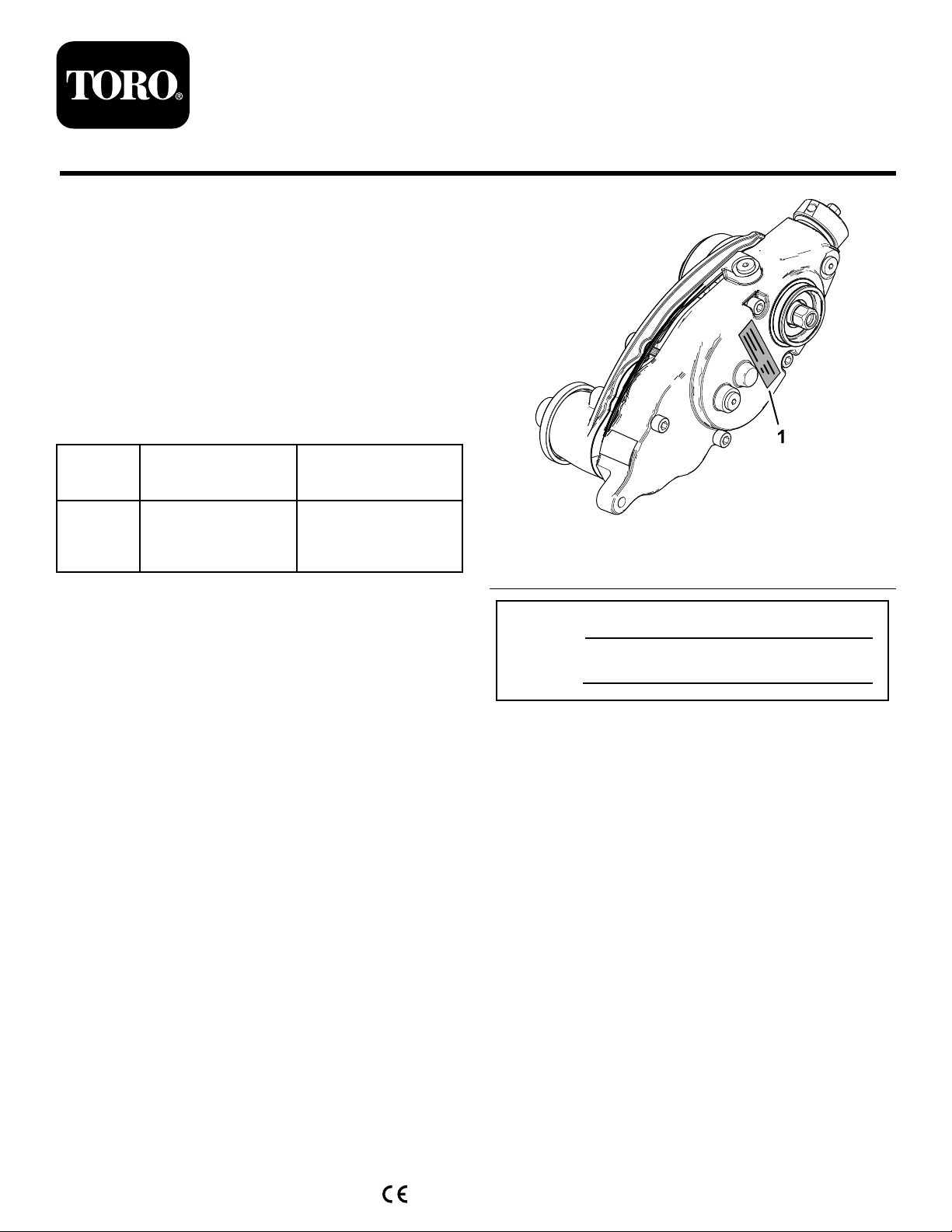
andserialnumbersofyourproductready.Figure1
identiesthelocationofthemodelandserialnumbers
ontheproduct.Writethenumbersinthespace
provided.
g357127
Figure1
1.Modelandserialnumberlocation
ModelNo.
SerialNo.
©2021—TheToro®Company
8111LyndaleAvenueSouth
Bloomington,MN55420
Registeratwww.Toro.com.OriginalInstructions(EN)
PrintedintheUSA
AllRightsReserved*3446-292*

LooseParts
Usethechartbelowtoverifythatallpartshavebeenshipped.
ProcedureDescriptionQty.Use
1Nopartsrequired–Preparethemachine.
2Torquewrench(Notincluded)–Gatherthetoolsrequiredforsetup.
3Nopartsrequired–Determinethegroomergearbox
position.
Extendedsplinedinsert(right-hand
threads)2
4Extendedsplinedinsert(left-hand
threads)1
Preparethecuttingunit.
Weightbracket3
Hex-socket,button-headbolt(3/8x3/4
inch)6
Groomerdrivebox(leftdrive)2
5
Groomerdrivebox(rightdrive)1
Installtheweightbracketandgroomer
drivebox.
Idlerassembly(left)1
Idlerassembly(right)2
O-ring3
Pivothub3
Socket-headscrew(3/8x3/4inch)6
6
Locknut(3/16—thin)6
Installtheidlerassembly.
Shoulderbolt6
Hardenedwasher3
LeftHOCbracketassembly3
RightHOCbracketassembly3
7Flangelocknut(3/8inchwith5/8inch
hex)6
InstalltheHOCbracketassembliesand
thefrontroller.
8
Cap(foruniversalgroomerassemblies
withnorearrollerbrushkitinstalled
only)
3Installthegroomerdrivecap.
Bolt(1/4x1-1/2inches)12
Jamnut12
Shaftclamp12
9Groomingreel(orderseparately)3
Installthegroomerassembly(ordered
separately)andoptionalbroomerkit.
10Washer(PartNo.3256-24,notincluded)–Adjustthegroomerspringforce.
Carriagebolt(5/16x3-1/2inches)6
Spacer6
Flangenut(5/16inch)6
11Weight18
Installtheweights(groomeronly,with
orwithoutfrontgrassbasketsandrear
cuttingunitwithoutreargrassbasket).
Carriagebolt(5/16x3-1/2inches)6
Spacer6
Flangenut(5/16inch)6
12Weight12
Installtheweights(withgroomerand
rearrollerbrush).
2

ProcedureDescriptionQty.Use
Carriagebolt(5/16x2-1/4inches),Part
No.3230-7—soldseparately1
Carriagebolt(5/16x3-1/4inches),Part
No.3230-13—soldseparately1
Carriagebolt(5/16x4-1/2inches),Part
No.3230-30—soldseparately1
Spacer2
Flangenut(5/16inch)1
Locknut(5/16inch),PartNo.
3296-47—soldseparately2
Weight2
13
Smallweight(PartNo.
132-0734-03—soldseparately)6
Installtheweights(rearcuttingunitwith
groomeronly,withreargrassbasket).
14Nopartsrequired–FinishinstallingtheUniversalGroomer
DriveKit.
1
PreparingtheMachine
ForCuttingUnitsInstalledonthe
Machine
NoPartsRequired
Procedure
1.Parkthemachineonalevelsurface.
2.Engagetheparkingbrake.
3.Lowerthecuttingunits.
4.Shutofftheengine,removethekey,andwaitfor
allmovingpartstostop.
5.Removethecuttingunitsfromthemachine;refer
totheOperator’sManualforthetractionunit.
2
GatheringtheTools
RequiredforSetup
Partsneededforthisprocedure:
–Torquewrench(Notincluded)
Note:Ensurethatthetorquewrenchesarecapable
oftorquingbothclockwiseandcounterclockwise.
•T orquewrench—5.2to6.8N∙m(46to60in-lb)
•T orquewrench—16to22N∙m(12to16in-lb)
•T orquewrench—20to26N∙m(15to19in-lb)
•T orquewrench—115to129N∙m(85to95ft-lb)
•T orquewrench—135to150N∙m(100to110ft-lb)
•Reeldriveshafttool,PartNo.TOR4074
•Long-handledprybar(3/8x12inches)
ServiceTools
Oilsyringe(included),PartNo.137-0872;referto
ChangingtheGearboxLubricant(page19).
Driveshafttool(optional),PartNo.137-0920;refer
toyourtractionunitServiceManualorcontactyour
authorizedT orodistributor.
3
3
DeterminingtheGroomer
GearboxPosition
NoPartsRequired
Procedure
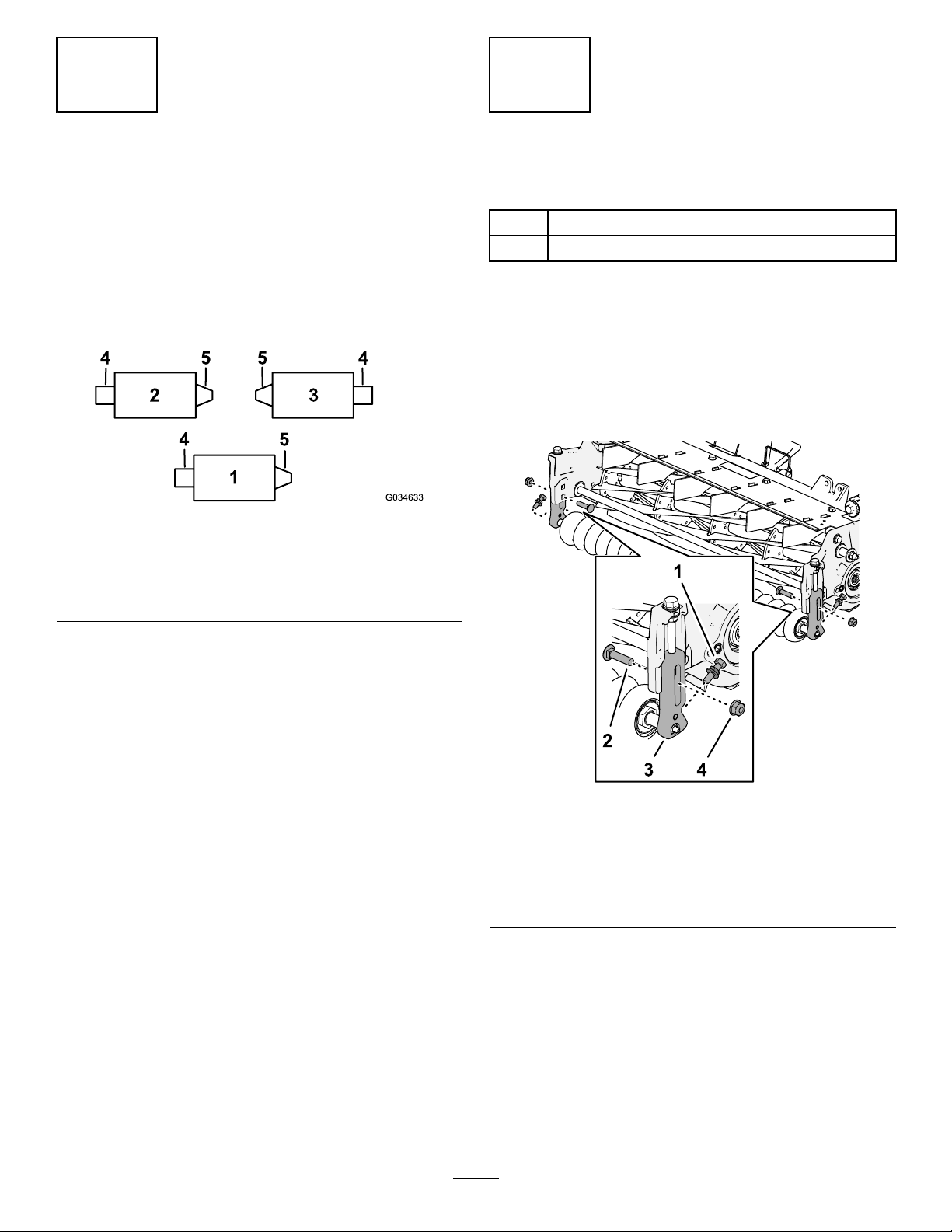
Usethefollowingdiagramtodeterminethepositionof
thegroomergearboxandreelmotors.
g034633
Figure2
1.Cuttingunit14.Groomergearboxposition
2.Cuttingunit25.Reelmotorposition
3.Cuttingunit3
Note:Ifyouareinstallingagroomerkitandyouare
installingtherearroller-brushkitontothecuttingunits,
installthegroomerkitrst.
4
PreparingtheCuttingUnit
Partsneededforthisprocedure:
2Extendedsplinedinsert(right-handthreads)
1Extendedsplinedinsert(left-handthreads)
RemovingtheFrontRollerand
HeightofCutBrackets
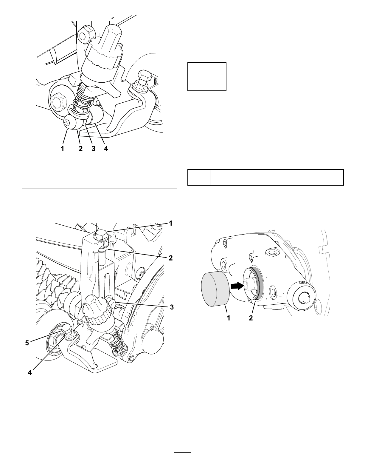
1.Loosenthe2angenuts(5/16inch)and2
capscrews(5/16x1-1/4inches)andsecuring
front-rollershafttothe2height-of-cutbrackets
(Figure3).
g356734
Figure3
1.Capscrew(5/16x1-1/4
inches)andangenut
(5/16inch)
3.Height-of-cutbracket
2.Carriagebolt(3/8x1-1/2
inches)
4.Flangelocknut(3/8inch)
2.Removetheangelocknut(3/8inch)and
carriagebolt(3/8x1-1/2inches)securingthe
height-of-cut(HOC)brackettothecutting-unit
sideplate(Figure3).
Note:Retainthecarriagebolt(3/8x1-1/2
inches).
Discardtheangenut(5/16inch),capscrew
(5/16x1-1/4inches),andangelocknut(3/8
inch).
4

3.Loosentheangelocknut(3/8inch)and
capscrew(3/8x3-7/8inches)intheheight-of-cut
bracket(Figure4).
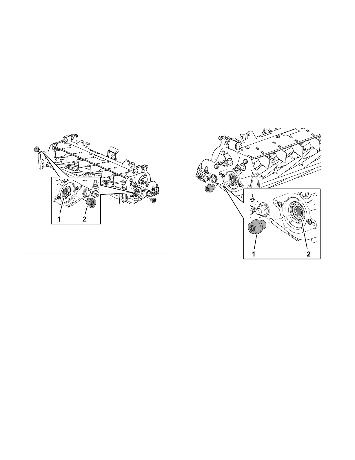
g356733
Figure4
1.Sideplate4.Height-of-cutbracket
2.Flangelocknut(3/8inch)5.Shaft(roller)
3.Capscrew(3/8x3-7/8
inches)
4.Removetheheight-of-cutbracketfromthe
sideplate,andremovetherollerfromthe
height-of-cutbrackets.
Note:Retainthefrontroller.
Discardtheangelocknut(3/8inch),capscrew
(3/8x3-7/8inches),andheight-of-cutbracket.
5.Repeatsteps2and3attheothersideor
thecuttingunit,andremovetheheight-of-cut
bracketformthesideplate.
RemovingtheSupportRod
Removethe2ange-headboltsandwasherssecuring
thesupportrod,andremovethesupportrod(Figure
5).
Note:Discardthesupportrodandange-headbolts.
g192295
Figure5
1.Flange-headbolts(2)3.Washer(2)
2.Supportrod
5
RemovingtheSplinedInsert
Lockingcompoundsolvent:Loctite®768™solvent
(59ml(2oz)HenkelPartNo.768X-NMS)
1.Restrainthereeltoremovetheexistingsplined
insert;refertoRestrainingtheReelforRemoving
ThreadedInserts(page21).
2.Usingthereeldriveshafttool(ToroPartNo.
TOR4074),removeanddiscardtheexisting
splinedinsertsfromeachendofthereel
driveshaft(Figure3).
Important:Thesplinedinsertattheleftside
ofthecuttingunithasleft-handthreads.The
splinedinsertattherightsideofthecutting
unithasright-handthreads.
g356735
Figure6
1.Reeldriveshaft2.Splinedinsert
3.UseLoctite768solventandawirebrushtoclean
thethreadsineachendofthereeldriveshaft.
4.Drythereel-driveshaftthreads.
AssemblingtheExtendedSplined
Insert
HydraulicMotorSide
Note:Thesplinedinsertattheleftsideofthecutting
unithasleft-handthreads.Thesplinedinsertatthe
rightsideofthecuttingunithasright-handthreads.
1.Restrainthereeltoinstalltheextendedsplined
insert;refertoRestrainingtheReelforInstalling
ThreadedInserts(page22).
2.Applymedium-strengththread-locking
compound(suchasBlueLoctite®243)tothe
threadsinthehydraulicmotorendofthereel
driveshaft.
g356732
Figure7
1.Extendedsplinedinsert2.Reeldriveshaft
3.Assembletheextendedsplinedinsertintothe
endofthereeldriveshaft(Figure7).
4.Torquetheinsertto115to128N∙m(85to95
ft-lb).
5.Allowthethread-lockingcompoundtocurefor
15minutes.
6
5
InstallingtheWeight
BracketandtheGroomer
DriveBox
Partsneededforthisprocedure:
3Weightbracket
6Hex-socket,button-headbolt(3/8x3/4inch)
2Groomerdrivebox(leftdrive)
1Groomerdrivebox(rightdrive)
AssemblingtheWeightBracketto
theCuttingUnit
1.Atthesideofthecuttingunitoppositeofthe
extendedsplinedinsert,aligntheholesinthe
weightbracketwiththeholesinthesideplate
(Figure8).
g356787
Figure8
1.Sideplate3.Socket-headscrew(3/8x
3/4inch)
2.Weightbracket
2.Assembletheweightbrackettothesideplate
withthe2socket-headscrews(3/8x3/4inch).
3.Torquethescrewsto37to45N∙m(27to33
ft-lb).
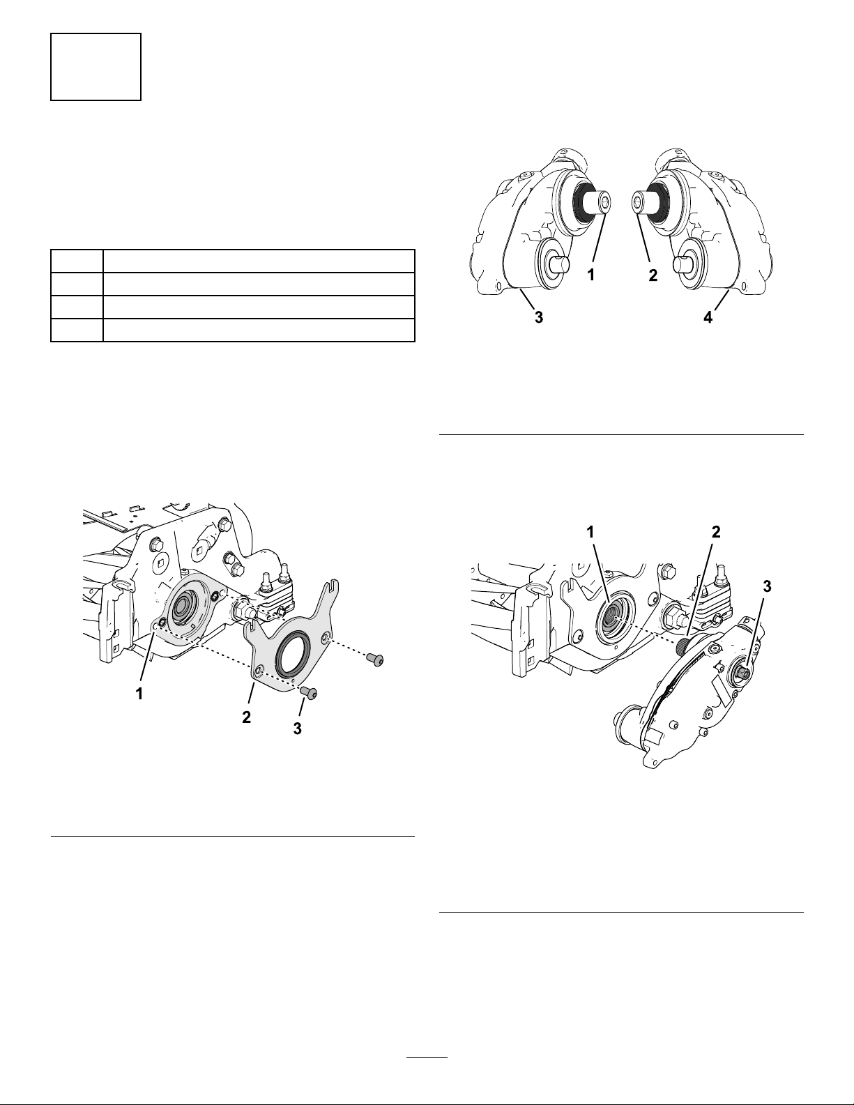
AssemblingtheGroomerGearbox
totheCuttingUnit
1.Identifytheleftdrivegroomerdriveboxesand
theright-drivegroomerdriveboxes;referto
Figure9.
g346922
Figure9
1.Right(yellow)adapter3.Groomerdrivebox—right
drive
2.Left(green)adapter4.Groomerdrivebox—left
drive
2.Applyacoatofmedium-strengththread-locking
compound(suchasBlueLoctite®243)tothe
threadsintheendofthereeldriveshaft(Figure
10).
g356786
Figure10
1.Reeldriveshaft3.Hex-head(gearbox
driveshaft)—torqueto
135to150N∙m(100to
110ft-lb)
2.Driveshaftadapter
(groomergearbox)
3.Alignthedriveshaftadapterwiththeendofthe
reeldriveshaft,andthethreadtheadapterinto
thereeldriveshaftbyturningthehex-headof
thegearboxdriveshaft.
7

Important:Thereelthreadsontheleftside
ofthecuttingunitareleft-handed,andthe
reelthreadsontherightsideofthecutting
unitareright-handed.
4.Restrainthecuttingreel;refertoRestrainingthe
ReelforInstallingThreadedInserts(page22).
5.Torquethehex-headofthegearboxdriveshaft
to135to150N∙m(100to110ft-lb).
Important:Youmustusea6-pointsocket
withheavywall.
Important:Donotuseanimpactwrenchfor
thisstep.
6.Allowthethread-lockingcompoundtocurefor
15minutesbeforecontinuingtheprocedure.
7.Ifyouareinstallingthegroomerattheleftsideof
themachine,performthefollowing(Figure11):
A.Removethehex-socketscrewthatsecures
theclutchknobtotheactuatorshaft.
B.Removetheclutch-knobassemblyandip
itover(Figure11).
C.Assembletheclutchknobtotheactuator
shaftwiththehex-socketscrew.
g298196
Figure11
1.Hex-socketbolt2.Clutch-knobassembly
8.Ifyouareinstallingarearrollerbrush,installthe
rearrollerbrushdrive;refertotheRearRoller
BrushKitInstallationInstructions.
6
InstallingtheIdler
Assembly
Partsneededforthisprocedure:
1Idlerassembly(left)
2Idlerassembly(right)
3O-ring
3Pivothub
6Socket-headscrew(3/8x3/4inch)
6Locknut(3/16—thin)
AssemblingtheIdlertotheCutting
Unit
1.AssembletheO-ringontothepivot-hub(Figure
12).
g356810
Figure12
1.Cuttingunit(hydraulic
motorside)
4.Pivot-hub(applyanti-seize
tothehuboutside
diameter)
2.Idlerassembly5.Socket-headscrew(3/8x
3/4inch)
3.O-ring6.Locknut(3/16—thin)
2.Applyacoatofanti-seizecompoundtothe
outsidediameterofthepivot-hub.
3.Positiontheidlerassemblyatthehydraulic
motorsideofthereel(oppositeofthegroomer
gearbox).
4.Insertthepivothubintotheidler,andassemble
thehubandidlertothecuttingunit(Figure12)
with2socket-headscrews(3/8x3/4inch).
8

5.Torquethesocket-headscrewsto37to45N∙m
(27to33ft-lb).
6.Looselyinstallthe2locknutsonthepivothub.
7
InstallingtheHOCBracket
AssembliesandtheFront
Roller
Partsneededforthisprocedure:
6Shoulderbolt
3Hardenedwasher
3LeftHOCbracketassembly
3RightHOCbracketassembly
6Flangelocknut(3/8inchwith5/8inchhex)
Procedure
1.LooselyinstalltheleftandrightHOCbracket
assembliesandthefrontrollerassemblytothe
cutting-unitsideplatesusingthepreviously
removedcarriagebolts(Figure13).
g246878
Figure13
1.RightHOCbracket
assembly
4.Carriageboltandange
locknut(3/8with5/8inch
hex)
2.Frontrollerassembly5.Washers
3.LeftHOCbracket
assembly
2.Applymedium-strengthcylindricalbonding
retainingcompound(suchasBlueLoctite242®)
totheshoulderboltspriortoinstallingthe
adjusterarmstothegroomerdriveboxandthe
idlerassembly.
3.Onthegroomerboxside,positionthe
adjuster-armrodoftheHOCbracketonthe
insideofthegroomerdriveboxandsecureit
withashoulderboltandahardenedwasheras
showninFigure14;torquetheshoulderboltto
16to22N⋅m(12to16ft-lb).
Note:Theshoulderboltmustbeinstalledfrom
theinsideofthemachinetotheoutsideofthe
machine.
g346924
Figure14
1.Shoulderbolt3.Hardenedwasher
2.Adjuster-armrod4.Groomerdrivebox
4.Ontheidlerassemblyside,alignthe
adjuster-armrodoftheHOCbracketwiththe
adjustercollarontheidlerassemblyandsecure
itwithashoulderboltasshowninFigure12;
torquetheshoulderboltto20to26N⋅m(15to
19ft-lb).
9
g346925
Figure15
1.Shoulderbolt3.Adjustercollar
2.Adjuster-armrod4.Idlerassembly
5.Tightenthecarriageboltsandlocknutssecuring
theHOCbracketassembliestothesideplates
(Figure16).
g346926
Figure16
1.Adjustingbolt4.Flangenut
2.Locknut5.Capscrew
3.Carriageboltandange
locknut(3/8with5/8inch
hex)
6.TightenthelocknutontheHOCadjusterbolt,
thenbackoffthelocknut1/2turn(Figure16).
7.CenterthefrontrollerbetweentheHOCbracket
assembliesandlockitinplacewiththecap
screwsandangenuts(Figure16).
8
InstallingtheGroomer
DriveCap
ForCuttingUnitswithoutaRear
RollerBrushKitOnly
Partsneededforthisprocedure:
3Cap(foruniversalgroomerassemblieswithnorear
rollerbrushkitinstalledonly)
Procedure
1.Cleanthemountingareaonthegearbox(Figure
17).
g355416
Figure17
1.Groomerdrivecap2.Mountingarea
2.ApplyalightcoatofLoctite609retaining
compound(green)tothemountingarea.
3.Installthegroomerdrivecapontothemounting
area(Figure17).
10

9
InstallingtheGroomer
AssemblyandOptional
BroomerKit
GroomerandBroomerKitsCome
Separately
Partsneededforthisprocedure:
12Bolt(1/4x1-1/2inches)
12Jamnut
12Shaftclamp
3Groomingreel(orderseparately)
InstallingtheOptionalGroomer
Kit
OrderedSeparately
ModelNumberGroomer
0324127-inchGroomerBladeCartridgeKit
1.Obtainagroomerbladecartridgekitorabrush
kitappropriateforyourneedsandcuttingunit;
refertothetableabove.
2.Lineupthegroomerassemblywiththe
drive-stubshaftsofthegroomerdriveboxand
idlerassembly(Figure18).
g240752
Figure18
1.Drive-stubshaft4.Shaftclamp(4)
2.Groomerassembly5.Bolt(4)Torqueto5to7
N∙m(46-60in-lb)
3.Jamnut(4)
3.Securethegroomertothemachineasshownin
Figure18using4bolts(1/4x1-1/2inches),4
jamnuts,and4shaftclamps.
4.Torquetheboltsto5to7N∙m(46to60in-lb).
InstallingtheOptionalBroomerKit
PartNumberBroomerKit
133-822227-inchBroomerKit
1.Obtaintheoptionalbroomerkitforgroomer
bladecartridgesappropriateforyourneedsand
cuttingunit;refertothetableabove.
2.Loosenthegroomerblade-retainingnutson
eachendofthegroomershaft(Figure19).
11
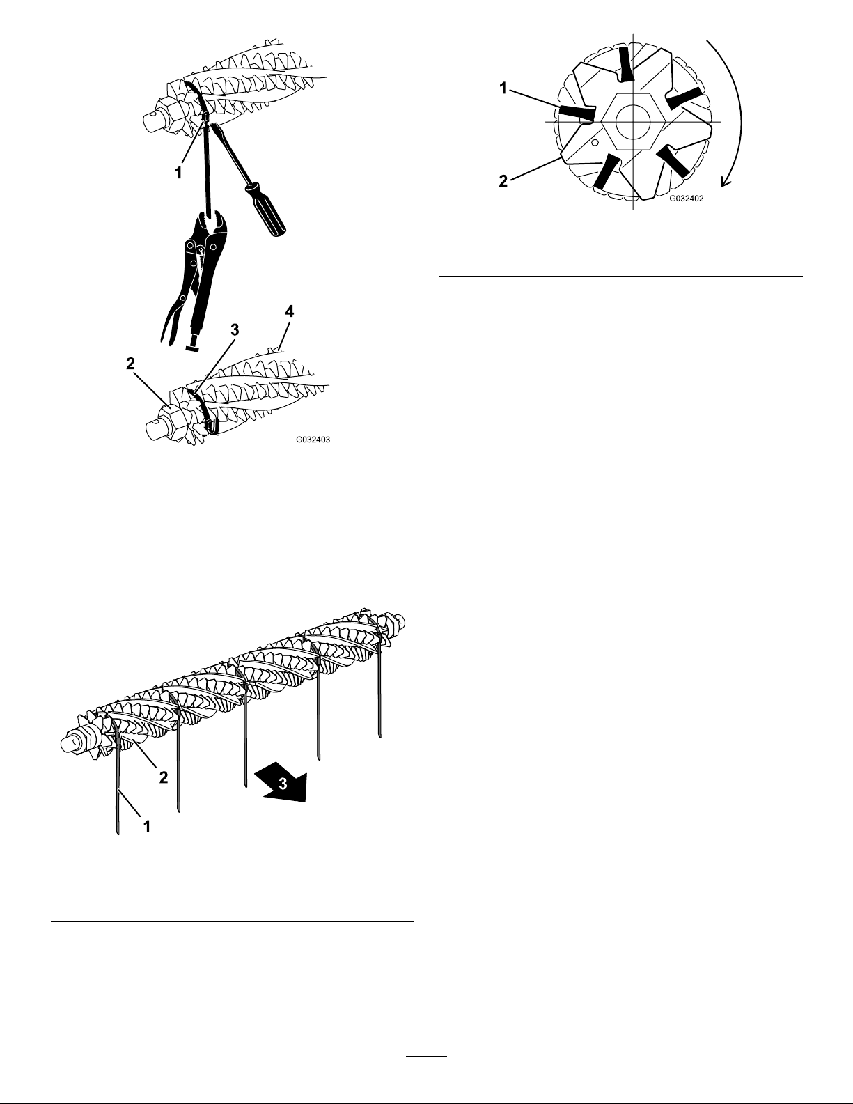
g032403
Figure19
1.Strapbuckle3.Strap
2.Retainingnut4.Brush
3.From1sideofthegroomerreel,slideabrush
intoeachgroovearoundthefulllengthofthe
groomerreel(Figure20).
g232518
Figure20
1.Strap3.T owardrearofmachine
2.Brush
4.Verifythatthebrushesareseatedinthegroomer
bladeslots(Figure19andFigure21).
g032402
Figure21
1.Brush2.Blade
5.Looselywrapthestraps,asshowninFigure
19,aroundthegroomerreelshaftandbrushes
insertingthestrapsinthegroovesinthebrushes
Figure21.
Positionthebrushessothatthestrapsare
betweenthefollowingblades:2and3;12and
13;23and24or24and25;35and36,and45
and46.
Important:Youmustwrapthestrapsaround
thegroomerbladeandbrushassemblyinthe
primaryrotatingdirection.Figure20shows
thestrapsinstalledforforwardrotation.
Note:Ifthebroomerbrushesarenot
seatedproperlyinthebladeslots,loosenthe
groomer-bladeretainingnutsoneachendofthe
groomershaft,positionthebroomerbrushes
properlyinthebladeslots,andtightenthe
groomer-bladeretainingnuts(Figure19).
6.Tightenthegroomerbladeretainingnuts;torque
themto45.2N∙m(400in-lb).
7.Whilepushingascrewdriveragainstthestrap
buckle,graspthestrapwithalockingpliersand
pullthestrapstightuntiltheylockintothebrush
grooves(Figure19).
8.Trimthestrapsothatitis6mm(1/4inch)from
thebuckleandfoldtheexcessstrapoverthe
buckle.
12

10
AdjustingtheGroomer
SpringForce(Optional)
Partsneededforthisprocedure:
–Washer(PartNo.3256-24,notincluded)
Procedure
Forlowheight-of-groomsetupswhereadditional
springforceisrequired(onlyifspringlengthis
above3/4inches),installadditionalwashers(Part
No.3256-24)totheeyebolttocompressthe
height-of-groomspringsatalowheightofgroom.
1.Setthedesiredcuttingunitheightofcut;referto
yourcuttingunitOperator’sManual.
2.Setthedesiredheightofgroom;referto
AdjustingtheGroomerHeight(page17).
3.Ensurethatthegroomeradjustersarein
theengaged(operating)position;referto
TransportingtheMachine(page19).
4.Measurethedistancebetweenthewashers(the
currentspringlength)asshowninFigure22.
g357750
Figure22
1.Topwasher4.Desiredspringlengthwith
optionalwashers–0.75
inches(19mm)
2.Additionalwashers(Part
No.3256-24)
5.Bottomwasher
3.Originalspringlength
(distancebetweentopand
bottomwashers)
5.Subtractthedesired(.75inchor19mm)spring
lengthfromthecurrentspringlength,anddivide
thisdifferenceby0.06inchestodeterminehow
manywashersyouneedtoaddtoachievethe
desiredspringlength.
6.Addorremovewashersbetweenthetopwasher
andthetopoftheeyeboltspringasfollows:
A.Fullyunthreadandremovetheadjusternut.
B.Removetheshoulderbolt(Figure14).
C.Lowertheeyebolt,removethetopwasher,
andadd/removewashersontopofthe
springasdesired.
Note:Boththeidlerandthegroomerboxsides
shouldhavethesamespringlengthandamount
ofwashers.
13

11
InstallingtheWeights
GroomerOnly,withorwithout
FrontGrassBasketsandRear
CuttingUnitwithoutRearGrass
Basket
Partsneededforthisprocedure:
6Carriagebolt(5/16x3-1/2inches)
6Spacer
6Flangenut(5/16inch)
18Weight
Procedure
Forcuttingunitswithonlythegroomerkitinstalled
(norearrollerbrushkitandnoreargrassbasket
installed),refertoFigure23.
g192300
Figure23
Groomeronly
1.Bolts(5/16x3-1/2inch)3.Flangenut—5/16inch(2)
2.Spacer(2)4.Weight(6)
12
InstallingtheWeights
GroomerandRearRollerBrush
Installed
Partsneededforthisprocedure:
6Carriagebolt(5/16x3-1/2inches)
6Spacer
6Flangenut(5/16inch)
12Weight
Procedure
Forcuttingunitswiththegroomerkitandtherear
rollerbrushkitinstalled,refertoFigure24.
Note:Thekitincludes6weightsforeachcutting
unit,however,thissetuprequiresonly4weightsper
cuttingunit.
g192302
Figure24
Groomerwithrearrollerbrushkitinstalled
1.Bolts(5/16x3inches)3.Flangenut—5/16inch(2)
2.Spacer(2)4.Weight(4)
14

13
InstallingtheWeights
RearCuttingUnitwithGroomer
Only,withRearGrassBasket
Partsneededforthisprocedure:
1Carriagebolt(5/16x2-1/4inches),PartNo.
3230-7—soldseparately
1Carriagebolt(5/16x3-1/4inches),PartNo.
3230-13—soldseparately
1Carriagebolt(5/16x4-1/2inches),PartNo.
3230-30—soldseparately
2Spacer
1Flangenut(5/16inch)
2Locknut(5/16inch),PartNo.3296-47—sold
separately
2Weight
6Smallweight(PartNo.132-0734-03—soldseparately)
Procedure
Forarearcuttingunitwiththegroomerkitandthe
reargrassbasketinstalled(norearrollerbrushkit),
refertoFigure25.
Alsoinstalltheweightsonthefrontcuttingunits.
Note:Forfrontcuttingunitswiththegroomerkitand
thefrontgrassbasketsinstalled(norearrollerbrush
kit),refertoFigure23.
Note:Thecentercuttingunitdoesnotworkwithboth
therearrollerbrushkitandthereargrassbasketkit.
g192301
Figure25
Rearcuttingunitwithgroomerandreargrassbasket
installed
1.Bolt(5/16x4-1/2inches),
soldseparately
5.Weight(2),suppliedwith
thekit
2.Bolt(5/16x2-1/4inches),
soldseparately
6.Locknut(5/16inch),sold
separately
3.Bolt(5/16x3-1/4inches),
soldseparately
7.Flangenut(5/16inch),
soldseparately
4.Spacer(2),soldseparately8.Smallweight(4),sold
separately
14
FinishingInstallingthe
UniversalGroomerDrive
Kit
NoPartsRequired
Procedure
1.Setthedesiredheightofgroomforeach
cuttingunit;refertoHeight-of-Cut(HOC)and
Height-of-Groom(HOG)Settings(page17)and
AdjustingtheGroomerHeight(page17).
2.Installthecuttingunits;refertotheOperator’s
Manualforyourmachine.
15

Operation
Introduction
Groomingisperformedintheturfcanopyabovethe
soillevel.Groomingpromotesverticalgrowthofgrass
plants,reducesgrain,andseversstolons,producing
adenserturf.Groomingproducesamoreuniform
andtighterplayingsurfaceforfasterandtrueraction
ofthegolfball.
Groomingshouldnotbeconsideredasareplacement
forverticutting.Verticuttingisgenerallyamore
rigorousandperiodictreatmentthatcantemporarily
damagetheplayingsurface,whilegroomingisa
routineandgentlertreatmentdesignedtomanicure
theturf.
g006671
Figure26
1.Grassrunners(stolons)2.Thatch
Groomingbrushesarelessintrusivethanconventional
groomingbladeswhenadjustedtolightlycontactthe
turfcanopy.Brushingmaybebetterfortheultra-dwarf
cultivars,sincethesegrasstypeshaveanupright
growthpatternanddonotllinwellthroughhorizontal
growth.Brushescaninjureleaftissueiftheyareset
topenetratetoodeeplyintothecanopy.
Groomerbladesshouldneverpenetratethesoil.They
areeffectiveincuttingrunnersandremovingthatch.
Becausegroominginjuresleaftissue,avoidgrooming
duringperiodsofhighstress.Coolseasonspecies,
suchascreepingbentgrassandannualbluegrass,
shouldnotbegroomedduringhigh-temperature(and
high-humidity)periodsinmidsummer.
Manyvariablesaffecttheperformanceofgrooming,
includingthefollowing:
•Thetimeoftheyear(i.e.,thegrowingseason)and
theweatherpattern
•Thegeneralconditionofthegrass
•Thefrequencyofgrooming/cutting—bothhow
manycuttingsperweekandhowmanypasses
percutting
•Theheight-of-cutsettingonthemainreel
•Theheight/depthsettingonthegroomingreel
•Howlongthegroomingreelhasbeeninuse
•Thetypeofgrass
•Theoverallmanagementprogram(i.e.,irrigation,
fertilizing,spraying,coring,overseeding,etc.)
•Trafc
•Stressperiods(i.e.,hightemperatures,high
humidity,unusuallyhightrafc)
Thesefactorscanvaryfromfairwaytofairway.
Inspectthemowingareafrequentlyandchangethe
groomingpracticeasneeded.
Note:Usingthegroomerreelimproperlyortoo
aggressively(i.e.,toodeeportoofrequentgrooming)
mayunnecessarilystresstheturf,causingsevereturf
damage.Usethegroomercautiously.
Note:Continuechangingthedirectionofcut
wheneveryouusethegroomer.Thisenhancesthe
effectsofthegrooming.
Note:Operatethegroomerinastraightlineasmuch
aspossible.Usecautionwhenturningwhileoperating
thegroomer.
16
Height-of-Cut(HOC)andHeight-of-Groom(HOG)Settings
UsetheHeight-of-Cut(HOC)andHeight-of-Groom(HOG)tabletodeterminetherecommendedengagement
ranges.
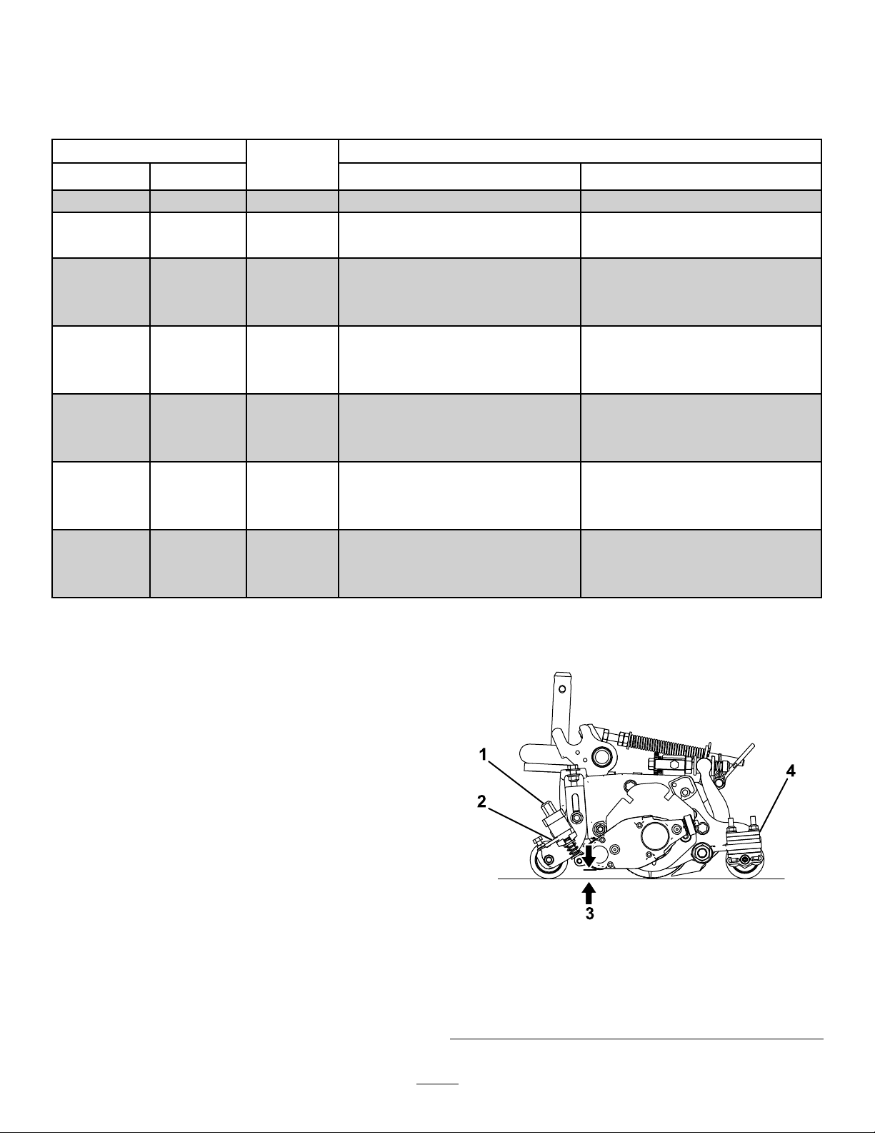
HOCandHOGRecommendedRangeTable
Height-of-CutRecommendedHOG=HOCGroomerEngagement
(mm)(inch)
Numberof
RearRoller
Spacers(mm)(inch)
6.30.25003.1to6.30.125to0.250
9.50.37504.7to9.50.187to0.375
9.50.37514.7to9.50.187to0.375
12.70.50006.3to12.70.250to0.500
12.70.50016.3to12.70.250to0.500
12.70.50026.3to9.50.250to0.375
15.80.62509.5to15.80.375to0.625
15.80.62519.5to15.80.375to0.625
15.80.62529.5to12.70.375to0.500
19.00.750112.7to19.00.500to0.750
19.00.750212.7to19.00.500to0.750
19.00.750312.7to15.80.500to0.625
22.20.875115.8to22.20.625to0.875
22.20.875215.8to22.20.625to0.875
22.20.875315.8to19.00.625to0.750
25.41.002*19.0to25.40.750to1.00
25.41.00319.0to25.40.750to1.00
25.41.00419.0to22.20.750to0.875
Note:MaximumHOGrecommendedishalftheHOCto6mm(1/4inch)maximumengagement
*Movethegroomerfrontheight-of-cut(HOC)brackettothebottom(cuttingunitlocation)side-platehole.
AdjustingtheGroomer
Height
1.Parkthemachineonacleanandlevelsurface,
lowerthecuttingunitscompletelytotheground,
shutofftheengine,engagetheparkingbrake,
andremovethekey.
2.Makesurethattherollersarecleanandthe
cuttingunitissettothedesiredheight-of-cut
(seeyourcuttingunitOperator’sManual).
3.Rotatethequick-uplevers(Figure27)tothe
ENGAGEDposition(thehandlepointstowardthe
frontofthecuttingunit.
Important:UsetheHeight-of-Cut(HOC)
andHeight-of-Groom(HOG)recommended
rangetableforsettingthegaugebar;refer
toHeight-of-Cut(HOC)andHeight-of-Groom
(HOG)Settings(page17).
g346928
Figure27
1.Heightadjusterknob3.Groomerheight(HOG)
2.Quick-uplever4.Numberofrearroller
spacers(belowsideplate
pad)
17
4.Attheendofthegroomerreel,measurethe
distancefromthelowesttipofthegroomerblade
totheworkingsurface(Figure27).Turnthe
heightadjusterknob(Figure27)toraiseorlower
thegroomerbladetiptothedesiredheight.
5.Repeatstep4attheoppositeendofthe
groomer,thencheckthesettingontherstside
ofgroomer.
Theheightsettingonbothendsofthegroomer
shouldbeidentical.Adjusttheheightas
required.
ChangingtheGroomer
OperatingDirection
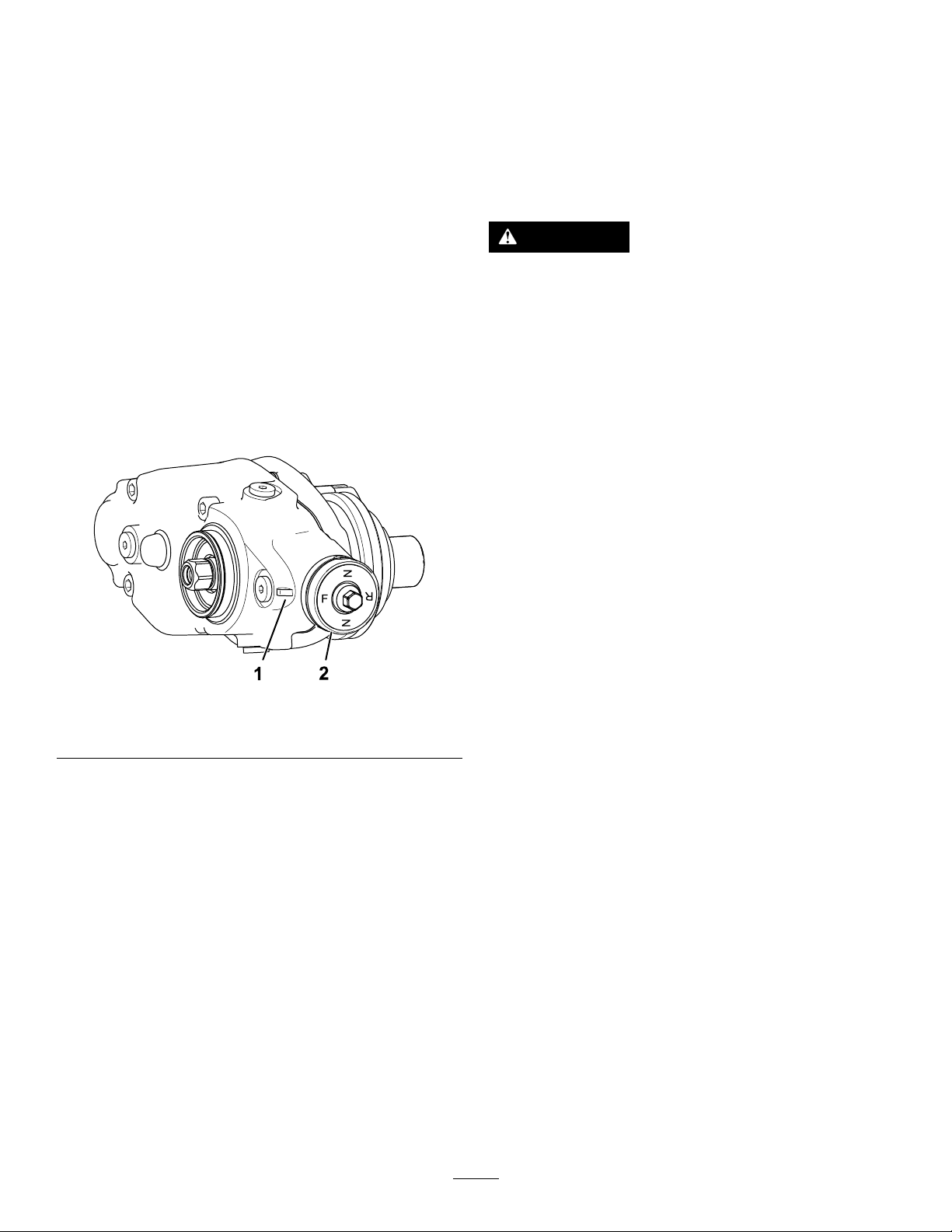
Thegroomerhas3settings:NEUTRAL,FORWARD,and
REVERSE.Tochangethedirectionofthegroomer,turn
theknobattheendofthegroomerdriveboxandalign
thedesiredpositionwiththeadjustmentnotch.
g246866
Figure28
1.Adjustmentnotch2.Knob
TestingtheGroomer
Performance
Important:Improperorover-aggressiveuseof
thegroomingreel(i.e.,toodeeportoofrequent
grooming)maycauseunnecessarystressonthe
turf,leadingtoseveredamage.Usethegroomer
cautiously.
DANGER
Contactwiththereelsorothermovingparts
canresultinpersonalinjury.
•Beforemakinganyadjustmentstothe
cuttingunits,disengagethereels,setthe
parkingbrake,shutofftheengine,and
removethekey.
•Keepyourhandsandclothingawayfrom
thereelsorothermovingparts.
Itisimportanttodeterminetheperformanceofthe
groomerbeforeputtingitintoregularuse.
1.Setthemaincuttingreelstotheheight-of-cut
settingthatyouwouldnormallyusewithoutthe
groomingreel.UseaWiehlerolleronthefront
andafullrollerontherear.
Theamountofgrassremovedisakeyindicator
indeterminingtheheight/depthsettingofthe
groomingreel.
2.Seteachofthegroomingreelstothedesired
heightsetting.
3.Examinethetestareaanddetermineifthe
groomedareasproducesthedesiredresults.
Ifnot,increaseordecreasetheheightofthe
groomersandmakeanothertestpass.
Checkthetestarea2or3daysaftertherst
groomingforgeneralconditionanddamage.Ifthe
groomedareasareturningyellowandbrown,andthe
non-groomedareasaregreen,thenthegroomingwas
tooaggressive.
18

TransportingtheMachine
Whenyouwishtomowwithoutthegroomerorneed
totransportthemachine,movethequick-upleverto
theTRANSPORTposition(Figure29).
Note:Thismovesthegroomerreelintoaraised
position.
g287375
Figure29
1.TRANSPORTposition2.OPERATIONposition
Maintenance
ChangingtheGearbox
Lubricant
ServiceInterval
Aftertherst100hours
Every500hours/Yearly(Whichevercomesrst)
1.Cleantheexternalsurfacesofthegroomer
housing.
Important:Ensurethatthereisnodirtor
clippingsontheoutsideofthegroomer
housing;ifdebrisgetsinsideofthegroomer
gearbox,damagemayoccur.
2.Removethedrainplugonthebottomofthe
housing(Figure32).
3.Removethellplugonthesideofthehousing
andloosentheair-ventplugonthetopsoair
canpassthrough(Figure32).
4.Alignasuitablecontainerbeneaththeoil-drain
porttocatchdrainedoil.
5.Tipthecuttingunitbackontothekickstand
untilthedrainportisatthebottomtoensure
completedrainage(Figure30).
g346929
Figure30
1.Removethedrainplug
fromthedrainport.
3.Loosentheair-ventplug.
2.Removethellplugfrom
thellport.
6.Rockthecuttingunitbackandforthtoensure
completedrainage.Whentheoiliscompletely
drained,placethecuttingunitonalevelsurface.
7.Installthedrainplug.
19
8.Useasyringe(PartNo.137-0872)tollthe
driveboxwith80-90Woil(approximately90cc).
g346931
Figure31
1.Syringewith80-90Woil2.Fillport
9.Installthellplugandtightentheair-ventplug.
10.Torqueallplugsto3.62to4.75N∙m(32to42
in-lb).
g346930
Figure32
Rightsidegroomerboxshown
1.Air-ventplug3.Drainplug
2.Fillplug
RemovingtheGroomer
DriveBox
Note:Retainallremovedpartsforlaterinstallation
unlessotherwisestated.
Important:Ifyouhaveanyissuesremovingthe
groomerdrivebox,refertoyourtractionunit
ServiceManualorcontactyourauthorizedToro
distributor.
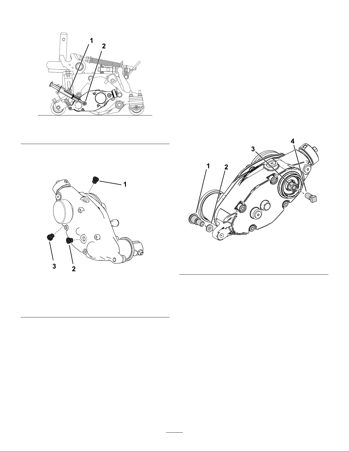
1.Removethecapfromthegroomer.
2.Removetheclampboltsconnectingthegroomer
tothedrivebox(Figure18).
3.Removetheshoulderboltandhardenedwasher
connectingthegroomerdriveboxtotheadjuster
arm(Figure33).
g346932
Figure33
1.Shoulderbolt3.Groomerdrivehex-head
2.Hardenedwasher4.Reinforcementscrew
4.Restrainthereelforremoval;refertoRestraining
theReelforRemovingThreadedInserts(page
21).
5.Installthereinforcementscrew(PartNo.
1-803022—soldseparately)totheinternal
threadsofthegroomerdrivehexheadand
torqueto13.5N⋅m(120in-lb)asshownin
Figure33.
6.Removethegroomerdriveboxfromthecutting
reelbyturningthegroomerdrivehex-head
(Figure33).
Important:Ifthegroomerdriveboxis
installedontherightsideofacutting
unit,turnthegroomerdrivehex-head
counter-clockwise(right-handthread)to
removethedrive-boxshaftfromcuttingunit.
Important:Ifthegroomerdriveboxis
installedontheleftsideofacuttingunit,
20
Other manuals for 03240
1
Other Toro Cutter manuals


