Toro MK3 User manual

FormNo.3393-413RevB
MK3200mm(8in)or250mm
(10in)CuttingUnit
ModelNo.02800—SerialNo.315000001andUp
ModelNo.02801—SerialNo.315000001andUp
ModelNo.02802—SerialNo.315000001andUp
ModelNo.02810—SerialNo.315000001andUp
ModelNo.02811—SerialNo.314000001andUp
ModelNo.02812—SerialNo.315000001andUp
Registeratwww.Toro.com.
OriginalInstructions(EN)*3393-413*B

ThisproductcomplieswithallrelevantEuropean
directives.Fordetails,pleaseseetheDeclarationof
Incorporation(DOI)atthebackofthispublication.
Introduction
Readthisinformationcarefullytolearnhowtooperate
andmaintainyourproductproperlyandtoavoid
injuryandproductdamage.Youareresponsiblefor
operatingtheproductproperlyandsafely.
YoumaycontactT orodirectlyatwww.Toro.com
forproductsafetyandoperationtrainingmaterials,
accessoryinformation,helpndingadealer,orto
registeryourproduct.
Wheneveryouneedservice,genuineT oroparts,or
additionalinformation,contactanauthorizedToro
distributorandhavethemodelandserialnumbersof
yourproductready.Themodelandserialnumbers
arelocatedontheleftsideofthecuttingunit.Write
thenumbersinthespaceprovided.
ModelNo.
SerialNo.
Thismanualidentiespotentialhazardsandhas
safetymessagesidentiedbythesafety-alertsymbol
(Figure1),whichsignalsahazardthatmaycause
seriousinjuryordeathifyoudonotfollowthe
recommendedprecautions.
g000502
Figure1
1.Safety-alertsymbol
Thismanualuses2wordstohighlightinformation.
Importantcallsattentiontospecialmechanical
informationandNoteemphasizesgeneralinformation
worthyofspecialattention.
Contents
Safety.......................................................................3
SafetyandInstructionalDecals..........................3
Setup........................................................................4
1PreparingtheMachine.....................................4
2InspectingtheCuttingUnit...............................4
3ConvertingtheCuttingUnitfromLeftto
RightConguration.........................................4
4AdjustingtheHand-WheelAssemblies............5
5InstallingtheCuttingUnittothe
Machine..........................................................6
6LubricatingtheCuttingUnit..............................6
ProductOverview.....................................................7
Specications....................................................7
Attachments/Accessories...................................7
Operation..................................................................8
OperatingtheCuttingUnit..................................8
AdjustingthePivotKnuckle................................8
AdjustingtheHeightofCut.................................8
ClearingtheCuttingCylinders............................9
Maintenance...........................................................10
CheckingtheCuttingUnittoBedknife
Contact.........................................................10
GreasingtheCuttingUnit..................................10
CheckingtheRear-RollerBearing
Adjustment.....................................................11
CheckingRearRollerScraperWire
Tension..........................................................11
AdjustingtheContactBetweentheCylinder
andBottomBlade.........................................12
BacklappingtheCuttingUnit.............................13
GrindingtheCuttingUnit...................................13
ReplacingtheBottomBlade.............................14
©2017—TheToro®Company
8111LyndaleAvenueSouth
Bloomington,MN554202
Contactusatwww.Toro.com.
PrintedintheUK
AllRightsReserved

Safety
Thismachinehasbeendesignedinaccordancewith
ENISO5395:2013.
Improperuseormaintenanceofthisequipment
canresultininjuryordeath.Toreducethe
potentialforinjuryordeath,complywiththe
followingsafetyinstructions.
•Read,understand,andfollowallinstructionsinthis
Operator’sManualbeforeoperatingthecutting
unit.
•Lowerthecuttingunitstotheground,engagethe
parkingbrake,shutofftheengine,andremovethe
keyfromtheignitionswitchwheneveryouleave
themachineunattended.
•Besurethatthecuttingunitsareinsafeoperating
conditionbykeepingnuts,bolts,andscrewstight.
SafetyandInstructionalDecals
Safetydecalsandinstructionsareeasilyvisibletotheoperatorandarelocatednearanyarea
ofpotentialdanger.Replaceanydecalthatisdamagedormissing.
decal40-13-010
40-13–010
1.Cuttinghazardofhand
2.Cuttinghazardoffoot
decal63-13-039
63–13–039
1.Height-of-cutadjustment
decal214053
214053
1.On-cutadjustment
3

Setup
LooseParts
Usethechartbelowtoverifythatallpartshavebeenshipped.
ProcedureDescriptionQty.Use
1Nopartsrequired–Preparethemachine.
2Nopartsrequired–Inspectthecuttingunit.
3Nopartsrequired–Convertthecuttingunitfromlefttoright
conguration.
4Nopartsrequired–Adjustthehand-wheelassemblies.
Pin1
Cap-headscrew2
Plainwasher2
5Springwasher2
Installthecuttingunitstothemachine.
6Nopartsrequired–Lubricatethecuttingunits.
WARNING
Theedgesofthecuttingcylinderandbottom
bladearesharp,andcontactwiththemcan
causeinjury.
Takecaretoavoidthesharpedgesofthe
cuttingcylinderandbottombladewhenlifting
orworkingonthecuttingunit.
WARNING
Thecuttingunitisheavy;liftingthecutting
unitimproperlycouldcauseinjury.
Usesuitableliftingequipmentwhenremoving
thecuttingunitfromthecartonandduring
installation.
1
PreparingtheMachine
NoPartsRequired
Procedure
1.Movethemachinetoalevelsurface.
2.Lowerthecuttingunitscompletelytotheground.
3.Shutofftheengineandremovethekey.
4.Engagetheparkingbrake.
5.Ensurethatthereisnopressureinthehydraulic
system.
6.Setthebattery-disconnectswitchtotheOFF
position.
2
InspectingtheCuttingUnit
NoPartsRequired
Procedure
1.Checkthatallpartsaredeliveredcorrectly.
2.Removethecuttingunitfromthecartonand
checkthatalllooseitemshavebeensupplied
correctly.
3.Ifanyitemsaremissingcontactyourauthorized
Torodistributor.
4
3
ConvertingtheCutting
UnitfromLefttoRight
Conguration
NoPartsRequired
Procedure
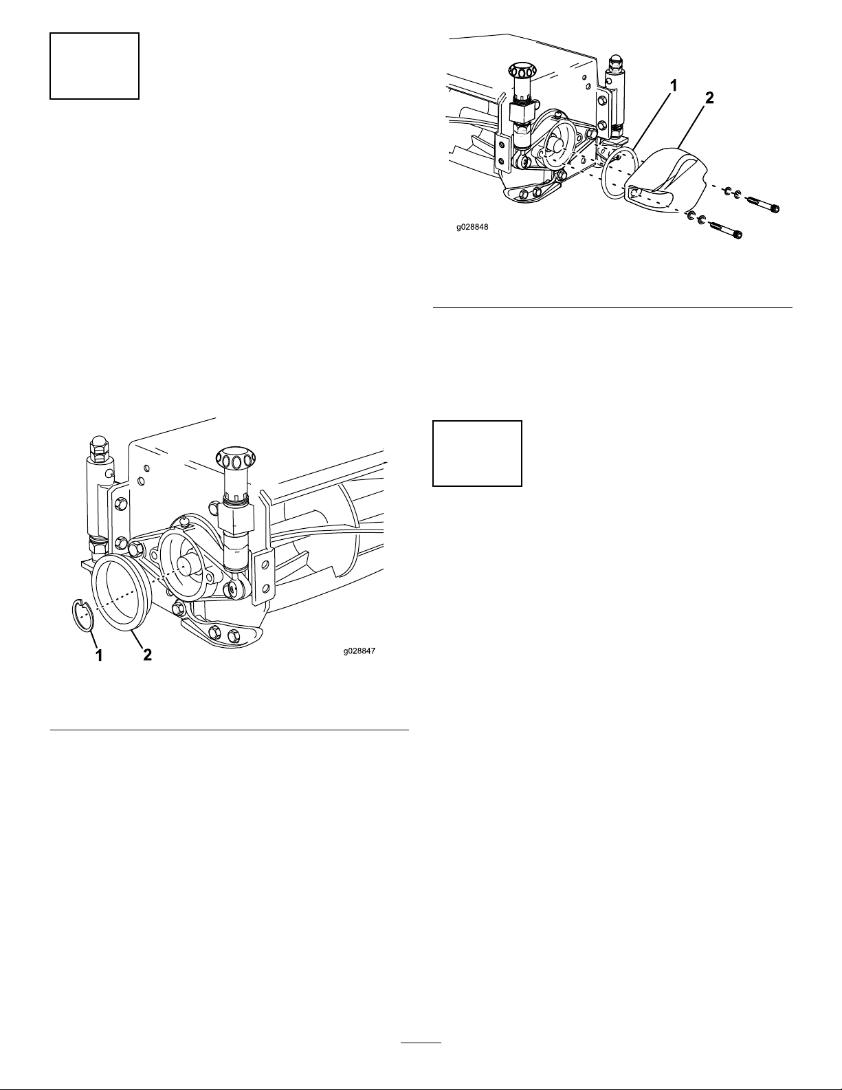
1.Removetheprotectivecoveranddiscardit
(Figure2).
2.Removethesnapring(Figure2).
Note:Thesnapringisttedtothedriveend
only.
g028847
Figure2
1.Snapring2.Protectivecover
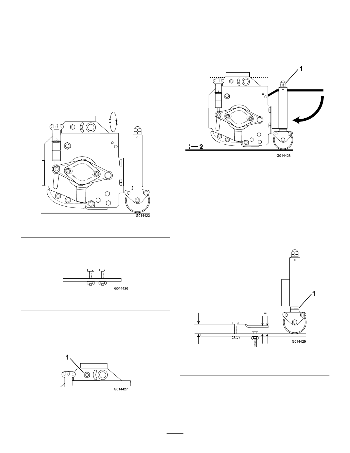
3.RemovethecounterweightandO-ringand
installthemtothenon-driveend(Figure3).
g028848
Figure3
1.O-ring2.Counterweight
4.Tighteneachofthe2socket-headcapscrews
toatorqueof80N·m(59ft-lb).
5.Installthesnapringtothedriveend.
6.Repeattheprocedurefortheothercuttingunits.
4
AdjustingtheHand-Wheel
Assemblies
NoPartsRequired
Procedure
1.Removethenut,bolt,andwasherfromthe
alternativeholeposition(Figure4).
2.Removethe2nuts,2washers,springwasher,
andbearing-adjusterpinthatattachesthe
hand-wheelassemblytothecuttingunit,and
thenremovethehand-wheelassembly(Figure
4).
5

g028992
Figure4
1.Bolt5.Nut
2.Alternativeholeposition6.Springwasher
3.Hand-wheelassembly7.Bearing-adjusterpin
4.Washer
3.Adjustthehand-wheelassemblysothatthe
fasteningcenteriscorrect.
4.Installthehand-wheelassemblyinthe
alternativeholeposition.
5.Installallfastenersandtightensecurely.
6.Repeattheprocedurefortheothercuttingunits
asnecessary.
5
InstallingtheCuttingUnit
totheMachine
Partsneededforthisprocedure:
1Pin
2Cap-headscrew
2Plainwasher
2Springwasher
Procedure
Note:Wheninstallingthecuttingunittothemachine,
youmayneedtoadjustthepositionofthehand-wheel
assemblies.Referto4AdjustingtheHand-Wheel
Assemblies(page5).
1.Unlatchandlowertherelevantarmtothe
ground.
2.For200mmcuttingunitsonly:
Removethepinassemblyalreadyttedtothe
arm,anddismantletheM24nut,M24washer,
nutcap,andpear-dropbushing.Installthese
itemsontothe353mmlongpinsuppliedwiththe
cuttingunit.Fitthisassemblyontothearm.
For250mmcuttingunitsonly:
Usingthe400mmlongpinalreadyttedtothe
arm,removethenutcap,nut,andwasherfrom
thepin.
3.Slidethecuttingunitontothepinuntilthearm
bushmateswiththepivotcasting.
4.InstalltheM24washerandlocknutandtighten.
5.Loosenthenutby1/8to1/4turntoallowthe
cuttingunittopivotfreely.
6.Attachthecuttingunitmotortothedriveendof
thecuttingunitusingthefastenersalreadytted
tothemotormounting.
7.Tightentheboltstoatorqueof80N·m(59ft-lb).
6
LubricatingtheCuttingUnit
NoPartsRequired
Procedure
FillallthebearinghousingswithNo.2lithiumgrease.
Note:Thisrequiresasignicantquantityofgrease.
RefertoGreasingtheCuttingUnit(page10).
6

ProductOverview
Specications
200mmcuttingunit254mmcuttingunit
4blade6blade8blade10blade4blade6blade8blade
Modelno.02800028010280202803028100281102812
Weight72kg75kg78kg81kg80.5kg83.5kg90kg
Cylinder
diameter
20cm(8inch)25.4cm(10inch)
Cuttingwidth76.2cm(30inch)76.2cm(30inch)
Heightofcut1.2to8.0cm(0.5to3.15inches)1.2to8.0cm(0.5to3.15inches)
RefertoyourPartsCatalogforalistofrecommendedbladesforyourcuttingunit.
Attachments/Accessories
AselectionofToroapprovedattachmentsand
accessoriesisavailableforusewiththemachineto
enhanceandexpanditscapabilities.Contactyour
AuthorizedServiceDealerorDistributororgoto
www.T oro.comforalistofallapprovedattachments
andaccessories.
Tobestprotectyourinvestmentandmaintainoptimal
performanceofyourT oroequipment,countonT oro
genuineparts.Whenitcomestoreliability,T oro
deliversreplacementpartsdesignedtotheexact
engineeringspecicationofourequipment.Forpeace
ofmind,insistonT orogenuineparts.
7
Operation
Note:Determinetheleftandrightsidesofthe
machinefromthenormaloperatingposition.
OperatingtheCuttingUnit
Whenthemowerissetupwithxedcuttingunits,
theheightofcutisgaugedbytherearrollerand
thecuttingunitisallowedtopivotlaterallytofollow
groundcontours.Thisarrangementisrecommended
forgeneralmowingrequirements(Figure5).
g014423
Figure5
Heightofcutgauge:Anoptionalheightofcutgauge
isavailabletoassistinachievingaccuratecutheight
settings(Figure6).
g014426
Figure6
AdjustingthePivotKnuckle
SecuretheboltinthefrontxedholepositioninFigure
7asshown.
g014427
Figure7
1.Frontxedholeposition
AdjustingtheHeightofCut
1.Theheightofcutisgaugedbythepositionof
therearroller.Turntheadjustingnutassembly
bothendsclockwisetodecreasetheheightof
cutorcounter-clockwisetoincreasetheheight
ofcut(Figure8).
g014428
Figure8
1.Adjustingnutassembly2.Heightofcut
Important:Donotattempttounlockthe
nuts.
2.Ensurethatallcuttingunitsaresetatthesame
heightofcutbyeitherreferringtotheindicator
ringsorbyusingaheight-of-cutgaugeacross
thefullwidthofeachcuttingunitforgreater
accuracyasshown(Figure9).
g014429
Figure9
1.Indicatorrings
3.Ifthecentercuttingunitproducesahigherheight
ofcutthanthewingcuttingunits,setthecenter
cuttingunitheight-of-cutindicatorringlower
thantheindicatorringofthewingcuttingunits.
8

ClearingtheCutting
Cylinders
WARNING
Neverattempttorotatethecuttingcylinders
byhand.
Theremaybesomeresidualpressureinthe
hydraulicsystem,whichcouldcauseinjury
throughsuddenmovementofthecylinder(s)
whenyoureleasetheblockage.
•Alwayswearprotectiveglovesandusea
suitablestrongwoodenstick.
•Ensurethatthewoodensticktsbetween
thebladesandthroughthecylinderandis
longenoughtoprovidesufcientclearance
andleveragetoreleasetheblockage.
1.Stopthemachineonlevelground.
2.Applytheparkingbrakeanddisengageall
drives.
3.Lowerthecuttingunitstothegroundorsecurely
lockinthedesignatedtransportpositions.
4.Shutofftheengineandremovethekeyto
isolateallpowersourcesandcheckthatthey
arestopped.
5.Releaseallstoredenergydevices.
6.Checkthatallmovingpartsarestationary.
7.Usingasuitablestrongwoodenstick,remove
theblockage.Makesurethatthewoodenstick
isproperlysupportedinthecylinderandavoid
theuseofexcessiveforcetopreventdamage.
8.Ensurethatthewoodenstickisremovedfrom
thecuttingcylinderbeforestartingtheengine.
9.Repairoradjustthecylinderifrequired.
9

Maintenance
CheckingtheCuttingUnit
toBedknifeContact
ServiceInterval:Beforeeachuseordaily
Eachdaybeforeoperatingthemachine,checkthe
cuttingunittobedknifecontact,regardlessifthe
qualityofcuthadpreviouslybeenacceptable.There
mustbelightcontactacrossthefulllengthofthe
cuttingunitandthebedknife.
GreasingtheCuttingUnit
ServiceInterval:Beforeeachuseordaily
GreaseType:No.2lithiumgrease
Lubricatethebearingsandbushingsimmediately
aftereverywashing,regardlessoftheintervallisted.
Replaceanygreaseorgreasettingsthatbecome
damaged.
Greaseallcuttingunitgreasepointsandensurethat
sufcientgreaseisinjectedsuchthatcleangrease
isseentoescapefromtherollerendcaps.This
providesvisibleevidencethattherollersealshave
beenpurgedofgrass,debris,etc.andensures
maximumworkinglife.
Thegreasettinglocationsandquantitiesareas
showninFigure10.
g028858
Figure10
1.–Greaseevery50hours2.–Greasedaily
10
CheckingtheRear-Roller
BearingAdjustment
ServiceInterval:Every50hours
Important:Keeptherollerbearingsinthecutting
unitsingoodadjustmentinordertoensure
maximumworkinglife.Excessiverollerendoat
willcauseprematurebearingdamage.
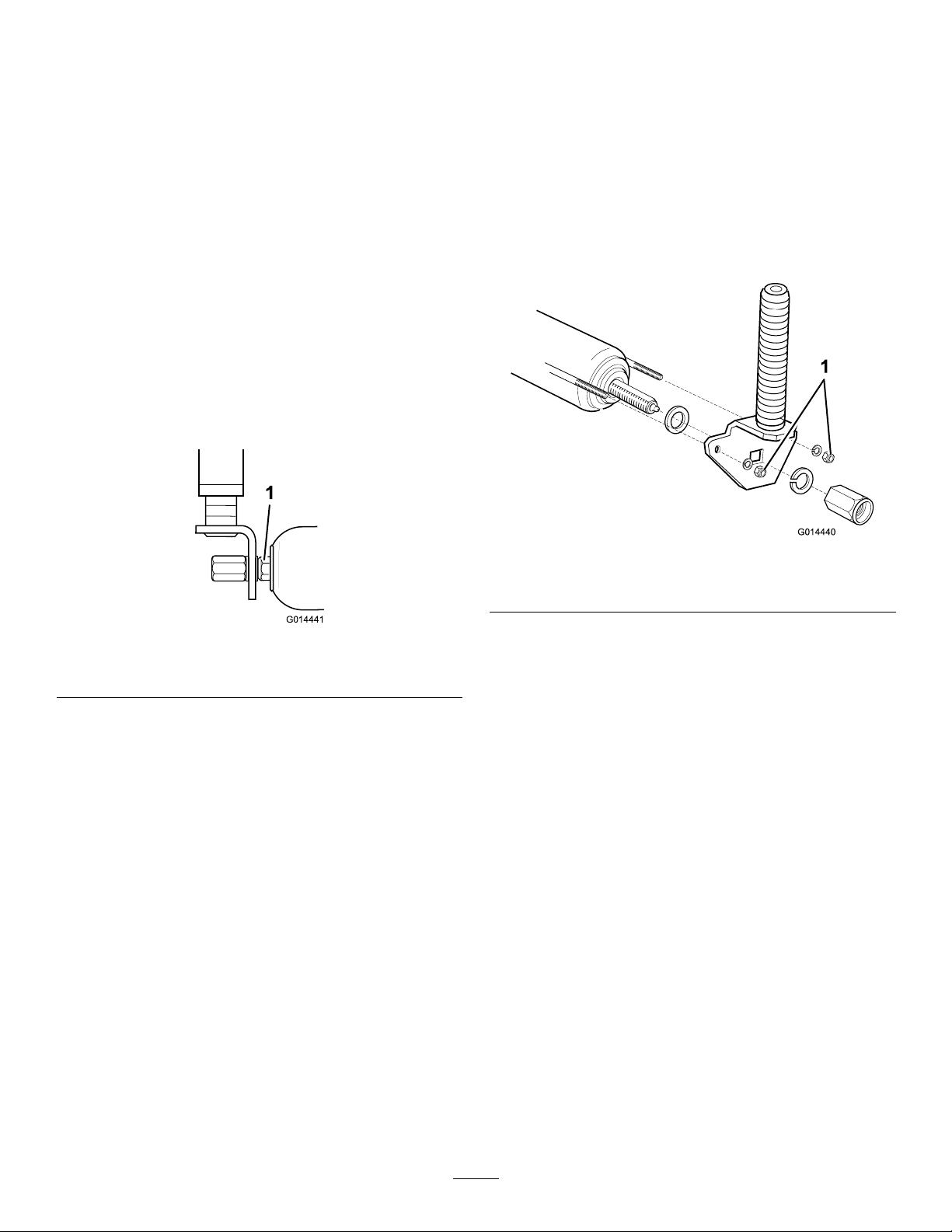
1.Griptherollerandmovefromsidetosideand
upanddown.
2.Ifyouseeexcessivemovement,carefullytighten
thenutsateachendoftherollerjustsufciently
toremoveanyendoat(Figure11).
Note:Therollershouldstillrotatefreelyafter
adjustment.Overtighteningthenutscouldlead
toprematurebearingdamage.
Adjustthenutsanequalamountatbothends
oftheroller.
g014441
Figure11
1.Nut
CheckingRearRoller
ScraperWireTension
ServiceInterval:Every50hours
Adjustthetensionofscraperwiresarecorrectlyto
ensurecorrectoperationandmaximumworkinglife.
1.Carefullytightenthescraperwireretainingnuts
toremoveanyslackfromthescraperwires.
2.Tightenthenuts4fullturnstocorrectlytension
thewire(Figure12).
g014440
Figure12
1.Scraperwireretainingnuts
Note:Donotovertightenthescraperwires.
11
AdjustingtheContact
BetweentheCylinderand
BottomBlade
ServiceInterval:Beforeeachuseordaily
Important:Itisessentialthattherelationship
betweenthebottombladesandthecuttingunits
arekeptingoodadjustmentinordertoensure
goodcuttingperformance,minimumpower
consumption,andprolongedlifeforthecutting
edges.Notmakingtheproperadjustmentsmay
resultinhighermaintenancecostsandalower
qualityofcutthatmayaffectthehealthand
growthofthegrass.
Important:Donotoveradjust.Over-adjusting
maycauseheavycontactbetweenthecylinder
andbottomblade,whichmaycreateveryrapid,
unevenwear,tramlining,wavinessofcutting
edges,increasedcontactpressure,andsignicant
powerabsorption.
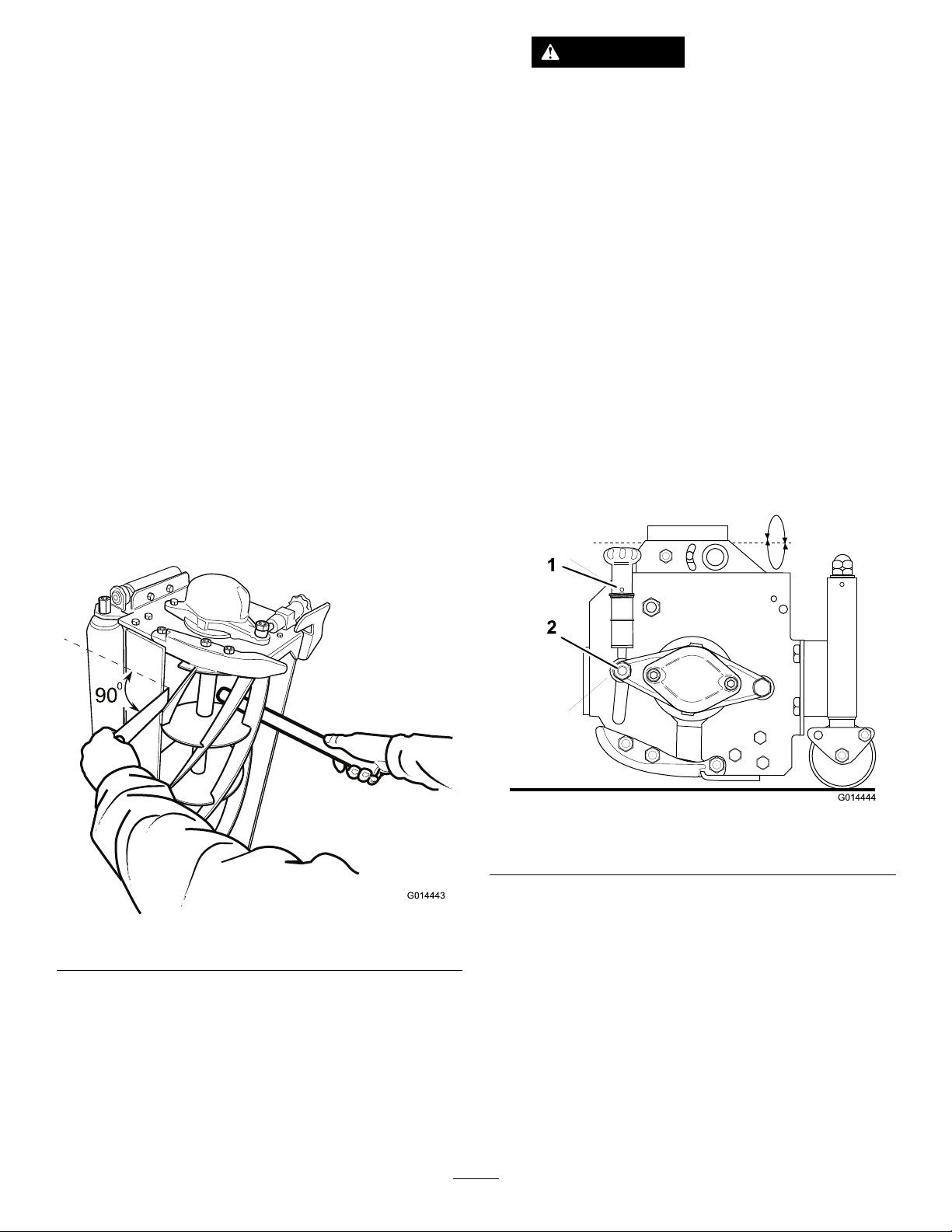
1.Checkthatthecuttingcylinderiscorrectlysetto
thebottombladebyholdingathinpieceofpaper
betweenthecuttingcylinderandthebottom
blade(Figure13).
g014443
Figure13
2.Carefullyrotatethecylinderasshownandcheck
thatthepaperiscutcleanlyatallpointsalong
thelengthoftheblade.Holdthepaperata90
degreerightangletothebottombladetoobtain
thecorrectcuttingaction.
WARNING
Thecuttingcylindersaresharp,and
contactwiththemcancauseinjury.Also,
rotating1ofthecuttingcylindersmay
causeotherstorotate,exposingothers
topotentialinjury.
Takecarewhenservicingthecutting
cylindersandensurethatbystandersare
awayfromthemachineandcuttingunits.
3.Stoptheprocedureifanadjustmentisnot
necessary.Otherwise,loosenthenutonboth
endsofthecuttingunit1/4turn(Figure14).
4.Turnthehandwheeloneachendalternately
whilerotatingthecuttingcylinderbackwarduntil
thebottombladeisineetingcontactwiththe
cylinderalongitsentirelength(Figure14).
5.Checkthecuttingactionalongthelengthofthe
bottombladeusingathinpieceofpaperand
makemarginaladjustmentsasnecessary.
6.Tightenthenutsoneachend(Figure14).
g014444
Figure14
1.Handwheel2.Nut
7.Ifyoucannotobtainagoodcleanpapercut
acrosstheentirelengthofthebottomblade,
backlapthecuttingunit(refertoBacklapping
theCuttingUnit(page13).Inseverecases,
grindingthecuttingcylinderandbottomblade
maybenecessary(refertoGrindingtheCutting
Unit(page13).
12

BacklappingtheCutting
Unit
WARNING
Contactwiththecuttingunitsorothermoving
partscanresultinpersonalinjury.
•Keepyourhandsandclothingawayfrom
thecuttingunitsorothermovingparts.
•Neverattempttoturnthecuttingunitsby
handorfootwhiletheengineisrunning.
Thisprocessisrecommendedforrestoringthesharp
cuttingedgestocylindersandbottombladeswhich
areessentialforgoodqualitygrasscutting.
Thisprocesscanonlyremoveasmallamountof
metaltorestorethecuttingedges.Ifthebladeedges
areseriouslywornordamaged,itwillbenecessaryto
removethecomponentpartsandgrindthem.
1.Turntheengineoffandapplytheparkingbrake.
2.Adjustthecuttingcylinderstothebottomblades
toobtaineetingcontact.
3.Applyamedium-gradedetergent-based
carborundumpastetothecuttingedgesofthe
cylinderswithalonghandledbrush.
80GradeCarborundumPaste
PartNo.
1lb(0.45kg)63-07-088
25lb(11.25kg)63-07-086
g014445
Figure15
4.Ensurethattheareasurroundingthecutting
unitsisclearofpeople.Keepyourhandsand
feetclearofthecuttingcylinderswhilethe
engineisrunning.
5.Sitontheoperatorseat,starttheengine,and
settheenginespeedatidle.
6.Operatethecuttingunitdriveswitchtothe
reverse/backlappositionforaperiodoftime
andlistentothegrindingaction.
g014443
Figure16
7.OperatethecuttingunitdriveswitchtotheOFF
positionandswitchofftheenginewhenthe
grindingactionhasstopped.
8.Thoroughlycleanthebladeedgesandadjustthe
cuttingcylinderstothebottomblades.Check
thatathinpieceofpapercanbecutcleanlyat
allpointsalongthecuttingedgeswhilerotating
thecylindersbyhand.
9.Iffurtherbacklappingisnecessaryrepeatsteps
2through8.
10.Thoroughlyremoveandwashoffalltracesof
thecarborundumpastefromthecylindersand
bottomblades.
GrindingtheCuttingUnit
Grindthecylinderspiraledgesorbottombladeedges
iftheybecomeexcessivelyroundedordistorted.
Replacethebottombladeswhentheyarenearthe
endoftheirwearlife.Grindnewbladesontheir
holderspriortotting.Whengrindingisnecessary,
grindbothcylindersandbottombladesatthesame
time,exceptwhenanewcylinderistted,inwhich
caseitisnecessaryonlytogrindthebottomblade.
Allgrindingoperationsshouldbeperformedby
yourauthorizedT orodistributoronaquality,well
maintainedcylinder/bottombladegrindingmachine.
13

ReplacingtheBottomBlade
RefertoyourPartsCatalogforalistofrecommended
bladesforyourcuttingunit.
Toensureoptimumperformanceandsafety,always
purchasegenuineTororeplacementpartsand
accessories.Replacementpartsandaccessories
madebyothermanufacturerscouldbedangerous.
Suchusecouldvoidtheproductwarranty.
1.Removethebottombladeholderbyremoving
the3xingboltsateachendandremovethem
fromthecuttingunit(Figure17).
g028860
Figure17
2.Removethewornbottombladeanddiscardthe
countersunkscrewsandsecuringnuts.
3.Fitthenewbladetotheholderandloosely
assemblewithnewcountersunkscrewsand
securingnuts(Figure18andFigure19).
4.Tightenthecenterboltstoatorqueof40N·m
(30lb-ft).
5.Tightentheremainingboltstoatorqueof40
N·m(30lb-ft)byworkingfromthecenterout
towardthebladeends.
6.Grindthenewbottombladeonitsholderprior
tottingtothecuttingunit.Adjustthecutting
cylinderpositiontogiveadequateclearancefor
ttingthenewbottombladeholder.
7.Installthebottombladeholderassemblytothe
cuttingunitusingtheoriginalxingboltsand
torquethemto35N·m(26lb-ft).
8.Adjustthecylindertothebottomblade.
g223071
Figure18
1.Bottomblade2.Countersunkscrew
g223072
Figure19
1.Securingnut
14

Notes:

Notes:

Notes:

DeclarationofIncorporation
TheT oroCompany,8111LyndaleAve.South,Bloomington,MN,USAdeclaresthatthefollowingunit(s)
conform(s)tothedirectiveslisted,wheninstalledinaccordancewiththeaccompanyinginstructionsontocertain
ToromodelsasindicatedontherelevantDeclarationsofConformity.
ModelNo.SerialNo.ProductDescriptionInvoiceDescriptionGeneralDescriptionDirective
02800315000001andUpMK3200mm(8in)4-Blade
CuttingUnit
MK3200MM(8")4-BLADE
CUTTERUNITCuttingUnit2006/42/EC
02801315000001andUpMK3200mm(8in)6-Blade
CuttingUnit
MK3200MM(8")6-BLADE
CUTTERUNITCuttingUnit2006/42/EC
02802315000001andUpMK3200mm(8in)8-Blade
CuttingUnit
MK3200MM(8")8-BLADE
CUTTERUNITCuttingUnit2006/42/EC
02803315000001andUpMK3200mm(8in)10-Blade
CuttingUnit
MK3200MM(8")10-BLADE
CUTTERUNITCuttingUnit2006/42/EC
02810315000001andUpMK3250mm(10in)4-Blade
CuttingUnit
MK3250MM(10")4-BLADE
CUTTERUNITCuttingUnit2006/42/EC
02811314000001andUpMK3250mm(10in)6-Blade
CuttingUnit
MK3250MM(10")6-BLADE
CUTTERUNITCuttingUnit2006/42/EC
02812315000001andUpMK3250mm(10in)8-Blade
CuttingUnit
MK3250MM(10")8-BLADE
CUTTERUNITCuttingUnit2006/42/EC
RelevanttechnicaldocumentationhasbeencompiledasrequiredperPartBofAnnexVIIof2006/42/EC.
Wewillundertaketotransmit,inresponsetorequestsbynationalauthorities,relevantinformationonthispartly
completedmachinery.Themethodoftransmissionshallbeelectronictransmittal.
ThismachineryshallnotbeputintoserviceuntilincorporatedintoapprovedToromodelsasindicatedonthe
associatedDeclarationofConformityandinaccordancewithallinstructions,wherebyitcanbedeclaredin
conformitywithallrelevantDirectives.
Certied:AuthorizedRepresentative:
MarcelDutrieux
ManagerEuropeanProductIntegrity
ToroEuropeNV
Nijverheidsstraat5
2260Oevel
Belgium
DonLackner
Sr.EngineeringManagerTel.+3216386659
8111LyndaleAve.South
Bloomington,MN55420,USA
July5,2017

EuropeanPrivacyNotice
TheInformationT oroCollects
ToroWarrantyCompany(T oro)respectsyourprivacy.Inordertoprocessyourwarrantyclaimandcontactyouintheeventofaproductrecall,weaskyou
tosharecertainpersonalinformationwithus,eitherdirectlyorthroughyourlocalT orocompanyordealer.
TheT orowarrantysystemishostedonserverslocatedwithintheUnitedStateswhereprivacylawmaynotprovidethesameprotectionasapplies
inyourcountry.
BYSHARINGYOURPERSONALINFORMATIONWITHUS,YOUARECONSENTINGTOTHEPROCESSINGOFYOURPERSONALINFORMATION
ASDESCRIBEDINTHISPRIVACYNOTICE.
TheWayT oroUsesInformation
Toromayuseyourpersonalinformationtoprocesswarrantyclaims,tocontactyouintheeventofaproductrecallandforanyotherpurposewhichwetell
youabout.T oromayshareyourinformationwithT oro'safliates,dealersorotherbusinesspartnersinconnectionwithanyoftheseactivities.Wewillnot
sellyourpersonalinformationtoanyothercompany.Wereservetherighttodisclosepersonalinformationinordertocomplywithapplicablelawsand
withrequestsbytheappropriateauthorities,tooperateoursystemsproperlyorforourownprotectionorthatofotherusers.
RetentionofyourPersonalInformation
Wewillkeepyourpersonalinformationaslongasweneeditforthepurposesforwhichitwasoriginallycollectedorforotherlegitimatepurposes
(suchasregulatorycompliance),orasrequiredbyapplicablelaw.
Toro'sCommitmenttoSecurityofYourPersonalInformation
Wetakereasonableprecautionsinordertoprotectthesecurityofyourpersonalinformation.Wealsotakestepstomaintaintheaccuracyandcurrent
statusofpersonalinformation.
AccessandCorrectionofyourPersonalInformation
Ifyouwouldliketorevieworcorrectyourpersonalinformation,pleasecontactusbyemailat[email protected].
AustralianConsumerLaw
AustraliancustomerswillnddetailsrelatingtotheAustralianConsumerLaweitherinsidetheboxoratyourlocalToroDealer.
374-0282RevC

TheToroTotalCoverageGuarantee
ALimitedWarranty
ConditionsandProductsCovered
TheToro®Companyanditsafliate,T oroWarrantyCompany,pursuant
toanagreementbetweenthem,jointlywarrantyourT oroCommercial
product(“Product”)tobefreefromdefectsinmaterialsorworkmanship
fortwoyearsor1500operationalhours*,whicheveroccursrst.This
warrantyisapplicabletoallproductswiththeexceptionofAerators
(refertoseparatewarrantystatementsfortheseproducts).Wherea
warrantableconditionexists,wewillrepairtheProductatnocosttoyou
includingdiagnostics,labor,parts,andtransportation.Thiswarranty
beginsonthedatetheProductisdeliveredtotheoriginalretailpurchaser.
*Productequippedwithanhourmeter.
InstructionsforObtainingWarrantyService
YouareresponsiblefornotifyingtheCommercialProductsDistributoror
AuthorizedCommercialProductsDealerfromwhomyoupurchasedthe
Productassoonasyoubelieveawarrantableconditionexists.Ifyouneed
helplocatingaCommercialProductsDistributororAuthorizedDealer,or
ifyouhavequestionsregardingyourwarrantyrightsorresponsibilities,
youmaycontactusat:
CommercialProductsServiceDepartment
ToroWarrantyCompany
8111LyndaleAvenueSouth
Bloomington,MN55420-1196
E-mail:[email protected]
OwnerResponsibilities
AstheProductowner,youareresponsibleforrequiredmaintenanceand
adjustmentsstatedinyourOperator’sManual.Failuretoperformrequired
maintenanceandadjustmentscanbegroundsfordisallowingawarranty
claim.
ItemsandConditionsNotCovered
Notallproductfailuresormalfunctionsthatoccurduringthewarranty
periodaredefectsinmaterialsorworkmanship.Thiswarrantydoesnot
coverthefollowing:
•Productfailureswhichresultfromtheuseofnon-T ororeplacement
parts,orfrominstallationanduseofadd-on,ormodiednon-T oro
brandedaccessoriesandproducts.Aseparatewarrantymaybe
providedbythemanufactureroftheseitems.
•Productfailureswhichresultfromfailuretoperformrecommended
maintenanceand/oradjustments.Failuretoproperlymaintainyour
ToroproductpertheRecommendedMaintenancelistedinthe
Operator’sManualcanresultinclaimsforwarrantybeingdenied.
•ProductfailureswhichresultfromoperatingtheProductinanabusive,
negligentorrecklessmanner.
•Partssubjecttoconsumptionthroughuseunlessfoundtobedefective.
Examplesofpartswhichareconsumed,orusedup,duringnormal
Productoperationinclude,butarenotlimitedto,brakespadsand
linings,clutchlinings,blades,reels,bedknives,tines,sparkplugs,
castorwheels,tires,lters,belts,andcertainsprayercomponents
suchasdiaphragms,nozzles,andcheckvalves,etc.
•Failurescausedbyoutsideinuence.Itemsconsideredtobeoutside
inuenceinclude,butarenotlimitedto,weather,storagepractices,
contamination,useofunapprovedcoolants,lubricants,additives,
fertilizers,water,orchemicals,etc.
•Normalnoise,vibration,wearandtear,anddeterioration.
•Normal“wearandtear”includes,butisnotlimitedto,damagetoseats
duetowearorabrasion,wornpaintedsurfaces,scratcheddecalsor
windows,etc.
Parts
Partsscheduledforreplacementasrequiredmaintenancearewarranted
fortheperiodoftimeuptothescheduledreplacementtimeforthatpart.
Partsreplacedunderthiswarrantyarecoveredforthedurationofthe
originalproductwarrantyandbecomethepropertyofT oro.T orowillmake
thenaldecisionwhethertorepairanyexistingpartorassemblyorreplace
it.Toromayuseremanufacturedpartsforwarrantyrepairs.
NoteRegardingDeepCycleBatteryWarranty:
Deepcyclebatterieshaveaspeciedtotalnumberofkilowatt-hoursthey
candeliverduringtheirlifetime.Operating,recharging,andmaintenance
techniquescanextendorreducetotalbatterylife.Asthebatteriesin
thisproductareconsumed,theamountofusefulworkbetweencharging
intervalswillslowlydecreaseuntilthebatteryiscompletelywornout.
Replacementofwornoutbatteries,duetonormalconsumption,isthe
responsibilityoftheproductowner.Batteryreplacementmayberequired
duringthenormalproductwarrantyperiodatowner’sexpense.
MaintenanceisatOwner’sExpense
Enginetune-up,lubricationcleaningandpolishing,replacementofItems
andConditionsNotCoveredlters,coolant,andcompletingRecommended
MaintenancearesomeofthenormalservicesT oroproductsrequirethat
areattheowner’sexpense.
GeneralConditions
RepairbyanAuthorizedToroDistributororDealerisyoursoleremedy
underthiswarranty.
NeitherTheToroCompanynorToroWarrantyCompanyisliablefor
indirect,incidentalorconsequentialdamagesinconnectionwiththe
useoftheToroProductscoveredbythiswarranty,includingany
costorexpenseofprovidingsubstituteequipmentorserviceduring
reasonableperiodsofmalfunctionornon-usependingcompletion
ofrepairsunderthiswarranty.ExceptfortheEmissionswarranty
referencedbelow,ifapplicable,thereisnootherexpresswarranty.
Allimpliedwarrantiesofmerchantabilityandtnessforusearelimitedtothe
durationofthisexpresswarranty.Somestatesdonotallowexclusionsof
incidentalorconsequentialdamages,orlimitationsonhowlonganimplied
warrantylasts,sotheaboveexclusionsandlimitationsmaynotapplytoyou.
Thiswarrantygivesyouspeciclegalrights,andyoumayalsohaveother
rightswhichvaryfromstatetostate.
CountriesOtherthantheUnitedStatesorCanada
CustomersshouldcontacttheirT oroDistributor(Dealer)toobtainguaranteepoliciesforyourcountry,province,orstate.Ifforanyreasonyouare
dissatisedwithyourDistributor'sserviceorhavedifcultyobtainingguaranteeinformation,contacttheT oroimporter.Ifallotherremediesfail,you
maycontactusatToroWarrantyCompany.
374-0277RevA
Table of contents
Other Toro Cutter manuals


Popular Cutter manuals by other brands


Silver King
Silver King KutLett SKK2 Technical manual and replacement parts list

GRAPHTEC
GRAPHTEC FC2240 Service manual

QEP
QEP 10-37 owner's manual

EINHELL
EINHELL BT-KF 150 Original operating instructions

Florida Pneumatic
Florida Pneumatic Universal Tool UT8748E General Safety Information & Replacement Parts

Land Pride
Land Pride RC2512 Series Operator's manual