Toro Greensmaster 3150 Series User manual

FormNo.3397-897RevB
8-Blade,11-Blade,and14-Blade
DPACuttingUnit
Greensmaster®3150or3250-DSeries
TractionUnit
ModelNo.04652—SerialNo.316000001andUp
ModelNo.04654—SerialNo.316000001andUp
ModelNo.04656—SerialNo.316000001andUp
Registeratwww.Toro.com.
OriginalInstructions(EN)*3397-897*B

ThisproductcomplieswithallrelevantEuropean
directives.Fordetails,pleaseseetheDeclarationof
Incorporation(DOI)atthebackofthispublication.
WARNING
CALIFORNIA
Proposition65Warning
Useofthisproductmaycauseexposure
tochemicalsknowntotheStateof
Californiatocausecancer,birthdefects,
orotherreproductiveharm.
Introduction
Thiscuttingunitisdesignedforcuttingturfongreens
andsmallfairwaysofgolfcourses.
Readthisinformationcarefullytolearnhowtooperate
andmaintainyourproductproperlyandtoavoid
injuryandproductdamage.Youareresponsiblefor
operatingtheproductproperlyandsafely.
YoumaycontactT orodirectlyatwww.T oro.comfor
productandaccessoryinformation,helpndinga
dealer,ortoregisteryourproduct.
Wheneveryouneedservice,genuineT oroparts,or
additionalinformation,contactanAuthorizedService
DealerorT oroCustomerServiceandhavethemodel
andserialnumbersofyourproductready.Figure1
identiesthelocationofthemodelandserialnumbers
ontheproduct.Writethenumbersinthespace
provided.
g020063
Figure1
1.Locationofthemodelandserialnumbers
ModelNo.
SerialNo.
Thismanualidentiespotentialhazardsandhas
safetymessagesidentiedbythesafety-alertsymbol
(Figure2),whichsignalsahazardthatmaycause
seriousinjuryordeathifyoudonotfollowthe
recommendedprecautions.
g000502
Figure2
1.Safety-alertsymbol
Thismanualuses2wordstohighlightinformation.
Importantcallsattentiontospecialmechanical
informationandNoteemphasizesgeneralinformation
worthyofspecialattention.
©2018—TheToro®Company
8111LyndaleAvenueSouth
Bloomington,MN554202
Contactusatwww.Toro.com.
PrintedintheUSA
AllRightsReserved

Contents
Safety.......................................................................3
GeneralSafety...................................................3
SafeOperatingPractices....................................3
SafetyandInstructionalDecals..........................4
Setup........................................................................5
InstallingtheRoller.............................................5
InstallingtheBallStuds.......................................5
InstallingtheHoopLink,OffsetLink,or
ChainLink.......................................................5
RepositioningtheCounterWeights.....................6
AdjustingtheCuttingUnit...................................7
ProductOverview.....................................................8
Specications....................................................8
Attachments/Accessories...................................8
Operation..................................................................8
Maintenance.............................................................9
SupportingtheCuttingUnit.................................9
AdjustingtheBedknife-to-ReelContact..............9
Relief-GrindingtheReel...................................10
AdjustingtheRear-RollerHeight........................11
AdjustingtheHeightofCut...............................12
AdjustingtheCut-OffBar..................................13
ServicingtheBedbar........................................13
CheckingtheTopGrindAngle...........................15
ReelGrindingSpecications.............................15
InstallingtheBedknife.......................................16
BacklappingtheCuttingUnit.............................17
Safety
Thismachinehasbeendesignedinaccordancewith
ENISO5395:2013andANSIB71.1-2012.
GeneralSafety
Thisproductiscapableofamputatinghandsand
feetandofthrowingobjects.Alwaysfollowallsafety
instructionstoavoidseriouspersonalinjury.
Usingthisproductforpurposesotherthanitsintended
usecouldprovedangeroustoyouandbystanders.
•Readandunderstandthecontentsofthis
Operator’sManualbeforestartingtheengine.
•Donotputyourhandsorfeetnearmoving
componentsofthemachine.
•Donotoperatethemachinewithoutallguards
andothersafetyprotectivedevicesinplaceand
workingonthemachine.
•Keepclearofanydischargeopening.Keep
bystandersandpetsasafedistanceawayfrom
themachine.
•Keepchildrenoutoftheoperatingarea.Never
allowchildrentooperatethemachine.
•Parkthemachineonalevelsurface,lowerthe
cuttingunits,disengagethedrives,engagethe
parkingbrake(ifprovided),shutofftheengine,
andremovethekeybeforeleavingtheoperator's
positionforanyreason.
Improperlyusingormaintainingthismachinecan
resultininjury.Toreducethepotentialforinjury,
complywiththesesafetyinstructionsandalwayspay
attentiontothesafety-alertsymbol(Figure2),which
meansCaution,Warning,orDanger—personalsafety
instruction.Failuretocomplywiththeseinstructions
mayresultinpersonalinjuryordeath.
Youcanndadditionalsafetyinformationwhere
neededthroughoutthisOperator’sManual.
SafeOperatingPractices
•ReadtheOperator’sManualforthetractionunit
andothertrainingmaterialcarefully.Befamiliar
withthecontrols,safetysigns,andtheproper
useoftheequipment.Iftheoperatorormechanic
cannotreadthelanguageofthismanual,itisthe
owner'sresponsibilitytoexplainthismaterialto
them.
•Becomefamiliarwiththesafeoperationofthe
equipment,operatorcontrols,andsafetysigns.
•Theowner/operatorcanpreventandisresponsible
foraccidentsthatmaycausepersonalinjuryor
propertydamage.
3

•Wearappropriateclothing,includingeye
protection;substantial,slip-resistantfootwear;
longpants,andhearingprotection.Tiebacklong
hairanddonotwearloosejewelry.
•Inspecttheareawheretheequipmentistobe
usedandremoveallobjects,suchasrocks,toys,
andwire,thatthemachinecanthrow.
•Checkthatoperator'spresencecontrols,safety
switches,andshieldsareattachedandfunctioning
properly.Donotoperatethemachineunlessthey
arefunctioningproperly.
•Stopthemachine,removethekey,andwaitfor
allmovingpartstostopbeforeinspectingthe
attachmentafterstrikinganobjectorifthereis
anabnormalvibrationinthemachine.Makeall
necessaryrepairsbeforeresumingoperation.
•Keepyourhandsandfeetawayfromthecutting
units.
•Keepallpartsingoodworkingconditionandall
hardwaretightened.Replaceallwornordamaged
decals.
•Awornordamagedbladecanbreak,anda
pieceofthebladecouldbethrowntowardyouor
bystanders,resultinginseriouspersonalinjuryor
death.
•Inspectthebladeperiodicallyforwearordamage.
•Usecarewhencheckingtheblades.Wrapthe
bladesorweargloves,andusecautionwhen
servicingtheblades.Onlyreplaceorsharpenthe
blades;neverstraightenorweldthem.
•Onmulti-bladedmachines,takecareasrotating1
bladecancauseotherbladestorotate.
SafetyandInstructionalDecals
Safetydecalsandinstructionsareeasilyvisibletotheoperatorandarelocatednearanyarea
ofpotentialdanger.Replaceanydecalthatisdamagedormissing.
decal104-7729
104–7729
1.Warning—readthe
instructionsbefore
servicingorperforming
maintenance.
2.Cutting/dismemberment
hazard;handorfoot—shut
offtheengineandwaitfor
movingpartstostop.
4

Setup
MediaandAdditionalParts
DescriptionQty.Use
Ballstud2Mountthistotheroller.
Operator'sManual1Readbeforeinstallingandoperatingthecuttingunit.
Partscatalog1Usethistoreferencepartnumbers.
InstallingtheRoller
Thecuttingunitisshippedwithoutafrontroller.
Obtainarollerfromyourdealerandinstallitonthe
cuttingunit,asfollows:
1.Removetheplowbolt,washer,andangenut
securingoneoftheheight-of-cutarmstothe
cuttingunitsideplate(Figure3).
g016936
Figure3
1.Height-of-cutarm4.Washer
2.Adjustingscrew5.Flangenut
3.Plowbolt6.Roller-mountingscrew
2.Loosentheroller-mountingscrewsinthe
height-of-cutarms(Figure3).
3.Slidetherollershaftintotheheight-of-cutarm
ontheoppositeendofthecuttingunit(Figure3).
4.Slidetheheight-of-cutarmontotherollershaft
(Figure3).
5.Looselysecuretherollertothecuttingunitwith
theheight-of-cutarmandfastenerspreviously
removed(Figure3).
6.Centertherollerbetweentheheight-of-cutarms.
7.Tightentheroller-mountingscrews(Figure3).
8.Adjusttothedesiredheight-of-cutandtighten
theheight-of-cutarmmountingfasteners.
InstallingtheBallStuds
Installaballstudoneachendofthefrontroller(Figure
4).
g020075
Figure4
1.Ballstud
InstallingtheHoopLink,
OffsetLink,orChainLink
Forcuttingunitsmountingonatractionunitwitha
serialnumberpriorto240000001,obtainandinstall
theproperliftlinkasfollows:
Note:The2boltsusedtomounttheliftlinkare
shippedinstalledonthecuttingunit.
•ForGreensmaster3120and3150tractionunits,
installthehooplinksuppliedwiththetractionunit.
Installthehooplinktothetopofthecuttingunit
with2bolts.T orquetheboltsto34to40N∙m(25
to30ft-lb)(Figure5).
5
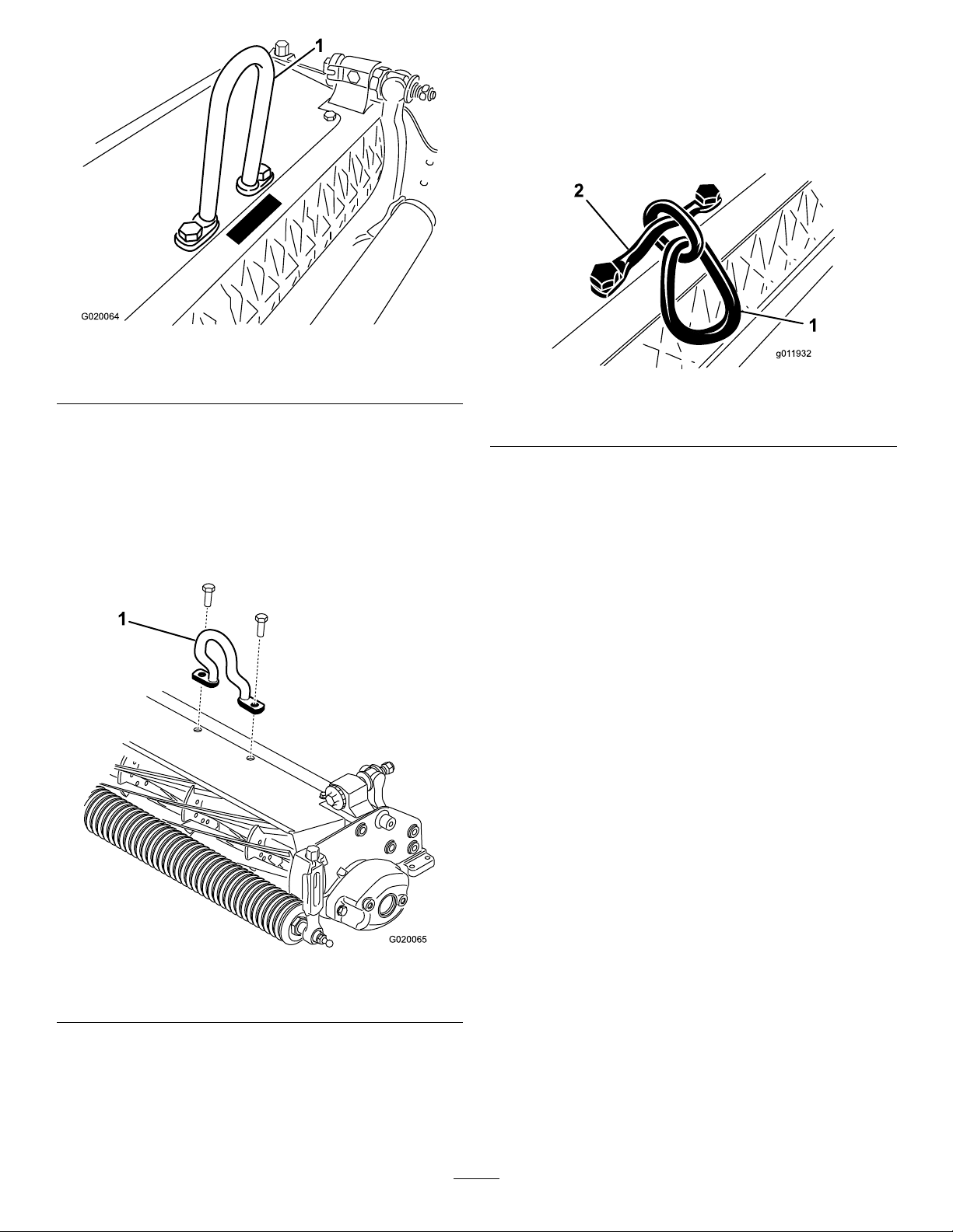
g020064
Figure5
1.Hooplink
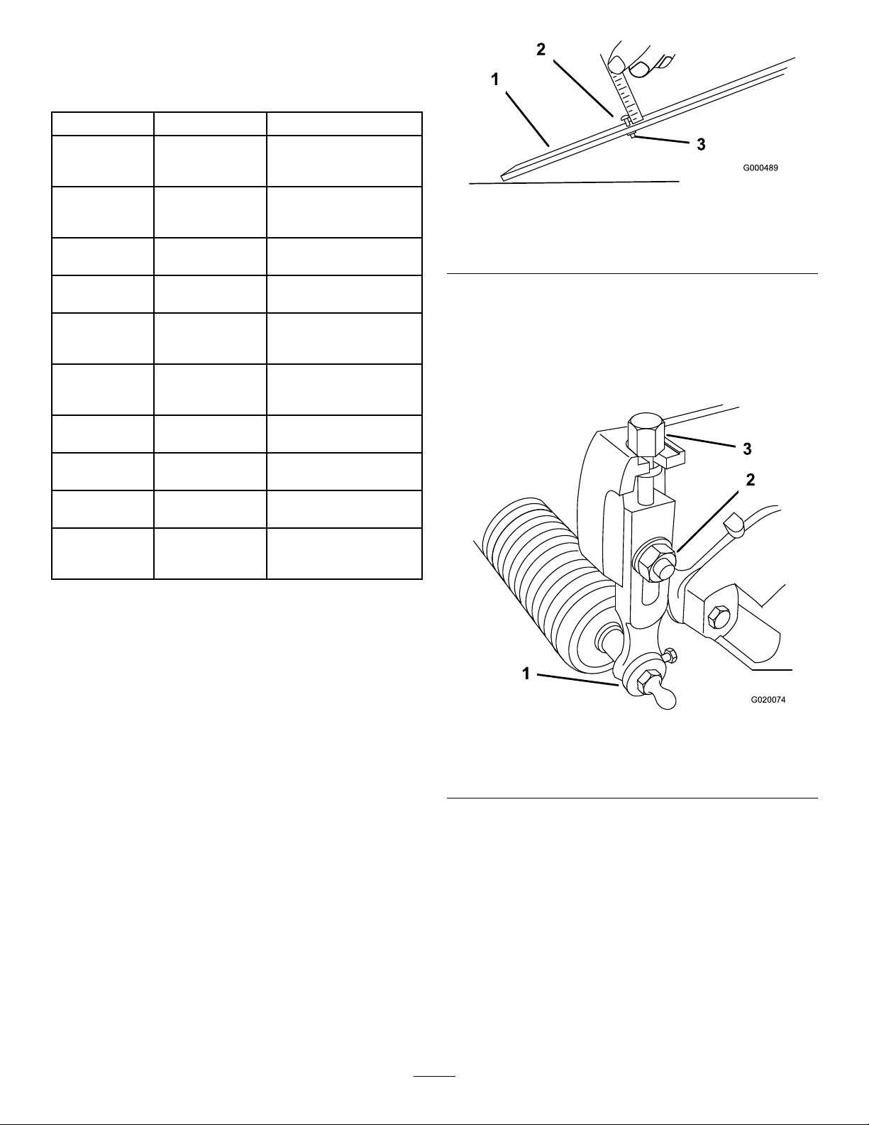
•FortheGreensmaster3250-Dtractionunits,install
theoffsetlinksuppliedwiththetractionunit.
Installtheoffsetlink(Figure6)tothetopofthe
cuttingunitwith2bolts.Torquetheboltsto34to
40N∙m(25to30ft-lb).
Important:Positionthelifthookoffsettoward
thefrontofthecuttingunit.
g020065
Figure6
1.Offsetlifthook
•OptionallyfortheGreensmaster3250-Dtraction
units,youcaninstallthechainLinkandmounting
bracketavailablefromyourauthorizedToro
distributor.
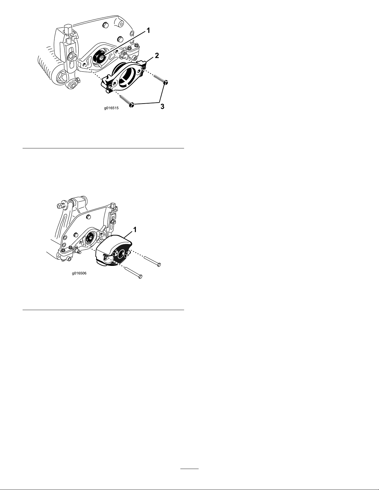
Installthechainlink(Figure7)tothetopofthe
cuttingunitwiththemountingbracketand2bolts.
Torquetheboltsto34to40N∙m(25to30ft-lb).
Note:Whenmountingthecuttingunittothe
tractionunit,hookthewiderendofthechainlink
totheliftarm.
g011932
Figure7
1.Chainlink2.Mountingbracket
RepositioningtheCounter
Weights
Thecuttingunitsareshippedwiththecounterweight
mountedtotheleftendandthemotormounttothe
rightendofthecuttingunit.T ochangethecuttingunit
todifferentpositions,proceedasfollows:
Important:Wheneveryouneedtotipthecutting
unitonitsside,ensurethatyoupropituptoavoid
damagingthebedbar-adjustingbolts;referto
SupportingtheCuttingUnit(page9)
1.Removethe2boltssecuringthecounterweight
totheleftendofthecuttingunit.Removethe
counterweight(Figure9).
2.Removethe2Allenheadboltssecuringthe
motormounttotheleftendofthecuttingunit.
Removethemotormount(Figure8).
3.Applygreasetotheinsidediameterofthedrive
spline(Figure8).
4.Ontheleftendofthecuttingunit,applyalight
coatingofoiltotheO-ringandinstallthemotor
mountwiththe2Allenheadboltspreviously
removed(Figure8).Torquetheboltsto16to
20N∙m(12to15ft-lb).
6
g016515
Figure8
1.Drivespline3.Allenheadbolts
2.Motormount
5.Ontherightendofthecuttingunit,applyalight
coatingofoiltotheO-ringandinstallthecounter
weightwiththeboltspreviouslyremoved(Figure
9).T orquetheboltsto16to20N∙m(12to15
ft-lb).
g016506
Figure9
1.Counterweight
AdjustingtheCuttingUnit
1.Supportthecuttingunit;refertoSupportingthe
CuttingUnit(page9).
2.Adjustthebedknifetothereel;refertoAdjusting
theBedknife-to-ReelContact(page9).
3.Adjusttherearrollerheight;refertoAdjusting
theRear-RollerHeight(page11).
4.Adjusttheheightofcut;refertoAdjustingthe
HeightofCut(page12).
5.Adjustthecut-offbar;refertoAdjustingthe
Cut-OffBar(page13).
7

ProductOverview
Specications
TractorsGreensmaster3120,3150,3250-D,and3150-QTractionUnits.
HeightofCutAdjustonthefrontrollerusing2verticalboltsandheld2lockingbolts.
Height-of-CutRangeStandardbenchheight-of-cutrangeis1.6mm(0.062inch)to12.7mm(0.500inch).Bench
height-of-cutrangewiththeHighHeightofCutKitinstalledis7mm(0.285inch)to25mm
(1.00inch).Effectiveheightofcutmayvarydependingonturfconditions,typeofbedknife,
rollers,andattachmentsinstalled.
CuttingWidth53cm(21inches)
ReelBearingsTwosealedstainlesssteel,deepgrooveballbearings
RollersTherearrollerisa5.1cm(2inch)diametersteelfullroller.
BedknifeReplaceablesingleedged,highcarbonsteelbedknifeisfastenedtoamachinedcastiron
bedbarwith13bolts
BedknifeAdjustmentDual-boltadjustmenttothereel;detentscorrespondingto0.018mm(0.0007inch)bedknife
movementforeachindexedposition
GrassShieldNon-adjustableshieldwithadjustablecut-offbartoimprovegrassdischargefromreelin
wetconditions
CounterweightAcastironweightmountedoppositetothedrivemotorbalancesthecuttingunit.
NetWeight8Blade—30kg(65lb),11Blade—31kg(68lb),14Blade—32kg(71lb)
Attachments/Accessories
AselectionofToroapprovedattachmentsandaccessoriesisavailableforusewiththemachinetoenhance
andexpanditscapabilities.ContactyourAuthorizedServiceDealerorDistributororgotowww.Toro.comfora
listofallapprovedattachmentsandaccessories.
Toensureoptimumperformanceandcontinuedsafetycerticationofthemachine,useonlygenuineT oro
replacementpartsandaccessories.Replacementpartsandaccessoriesmadebyothermanufacturerscouldbe
dangerous,andsuchusecouldvoidtheproductwarranty.
Operation
RefertoyourtractionunitOperator’sManualfordetailedoperationinstructions.Beforeusingthecuttingunit
eachday,adjustthebedknife;refertoAdjustingtheBedknife-to-ReelContact(page9).Testthequalityofcut
bycuttingatestswathbeforeusingthecuttingunitonagreentoensurethatthenishedcutiscorrect.
8

Maintenance
Note:Determinetheleftandrightsidesofthe
machinefromthenormaloperatingposition.
SupportingtheCuttingUnit
Wheneveryouneedtotipthecuttingunittoexpose
thebedknife/reel,propuptherearofthecutting
unittoensurethatthenutsonthebackendofthe
bedbar-adjustingboltsarenotrestingonthework
surface(Figure10).
g016511
Figure10
1.Prop(notprovided)2.Bedbar-adjusting-screw
nut(2)
Adjustingthe
Bedknife-to-ReelContact
AdjustingtheBedknifeDaily
Priortomowingeachday,orasrequired,verifyproper
bedknife-to-reelcontact.Performthisprocedure
eventhoughthequalityofcutisacceptable.
1.Lowerthecuttingunitsontoahardsurface,shut
offtheengine,andremovetheignitionkey.
2.Slowlyrotatethereelinareversedirection,
listeningforreel-to-bedknifecontact.
•Ifnocontactisevident,adjustthebedknife
asfollows:
A.Turnthebedbaradjustingscrews
clockwise(Figure11),1clickatatime,
untilyoufeelandhearlightcontact.
Note:Thebedbaradjustingscrews
havedetentscorrespondingto0.018
mm(0.0007inch)bedknifemovement
foreachindexedposition.
g026076
Figure11
1.Bedbaradjustingscrew
2.Bedbar-adjusting-screwnut(2)
B.Insertalongstripofcuttingperformance
paperbetweenthereelandbedknife,
perpendiculartothebedknife(Figure
12),thenslowlyrotatethereelforward;
itshouldcutthepaper;ifnot,repeat
stepsAandBuntilitdoes.
•Ifexcessivecontact/reeldragisevident,
backlap,refacethefrontofthebedknife,or
grindthecuttingunittoachievethesharp
edgesneededforprecisioncutting(Referto
theToroManualforSharpeningReeland
RotaryMowers,FormNo.09168SL).
Important:Lightcontactispreferredatall
times.Ifyoudonotmaintainlightcontact,
thebedknife/reeledgeswillnotsufciently
self-sharpen,anddullcuttingedgeswill
resultafteraperiodofoperation.Ifyou
maintainexcessivecontact,bedknife/reel
wearwillbeaccelerated,unevenwearcan
result,andthequalityofcutmaydecline.
Note:Asthereelbladescontinuetorunagainst
thebedknife,aslightburrwillappearonthefront
cuttingedgesurfacealongthefulllengthofthe
bedknife.Occasionallyrunaleacrossthefront
edgetoremovethisburrtoimprovecutting.
Afterextendedrunning,aridgewilleventually
developatbothendsofthebedknife.Round
offthesenotchesorlethemushwiththe
cuttingedgeofthebedknifetoensuresmooth
operation.
9

AdjustingtheBedknifetotheReel
Usethisprocedureduringinitialcutting-unitsetupand
aftergrinding,backlapping,ordisassemblingthereel.
Thisisnotadailyadjustment.
1.Positionthecuttingunitonaat,levelwork
surface.
2.Tipthecuttingunittoexposethebedknifeand
reel.
Note:Ensurethatthenutsonthebackofthe
bedbaradjustingboltsarenotrestingonthe
worksurface(Figure10).
3.Rotatethereelsothat1ofthebladescrosses
thebedknifeedgebetweentherstandsecond
bedknifeboltheadslocatedontherightsideof
thecuttingunit.
4.Makeanidentifyingmarkonthebladewhereit
crossesthebedknifeedge.
Note:Thiswillmakelateradjustmentseasier.
5.Inserta0.05mm(0.002inch)shimbetweenthe
bladeandthebedknifeedgeatthepointmarked
instep4.
6.Turntherightbedbaradjustingbolt(Figure11)
untilyoufeellightpressureontheshimwhen
slidingitside-to-side.Removetheshim.
7.Fortheleftsideofthecuttingunit,slowlyrotate
thereelsothattheclosestbladecrossesthe
bedknifeedgebetweentherstandsecondbolt
heads.
8.Repeatsteps4through6fortheleftsideofthe
cuttingunitandleftbedbaradjustingbolt.
9.Repeatsteps5and6untilthereislightpressure
atthecontactpointsonboththeleftandright
sidesofthecuttingunit.
10.Toobtainlightcontactbetweenthereeland
bedknife,turneachbedbaradjustingbolt
clockwise3clicks.
Note:Eachclickonthebedbaradjustingbolt
movesthebedknife0.018mm(0.0007inches).
Donotovertightentheadjustingbolts.
Turningtheadjustingboltclockwisemoves
thebedknifeedgeclosertothereel.Turning
theadjustingboltcounterclockwisemovesthe
bedknifeedgeawayfromthereel.
11.Insertalongstripofcuttingperformancepaper
betweenthereelandbedknife,perpendicularto
thebedknife(Figure12),thenslowlyrotatethe
reelforward;itshouldcutthepaper;ifnot,turn
eachbedbaradjustingboltclockwise1clicks
andrepeatthisstepuntilitcutsthepaper.
g000487
Figure12
Note:Ifexcessivecontact/reeldragisevident,
backlap,refacethefrontofthebedknife,orgrind
thecuttingunittoachievethesharpedgesneeded
forprecisioncutting(RefertotheToroManualfor
SharpeningReelandRotaryMowers,FormNo.
09168SL).
Relief-GrindingtheReel
Thenewreelhasalandwidthof1.3to1.5mm(0.050
to0.060inch)anda30degreereliefgrind.
Whenthelandwidthgetslargerthan3mm(0.120
inch)wide,dothefollowing:
1.Applya30degreereliefgrindonallreelblades
untilthelandwidthis1.3mm(0.050inch)wide
(Figure13andFigure14).
g028800
Figure13
Model03638
1.30degrees2.1.3mm(0.050inch)
10

g028838
Figure14
Models03639and03641
1.1.3mm(0.050inch)2.30degrees
2.Spingrindthereeltoachieve<0.025mm(0.001
inch)reelrun-out.
Note:Thiscausesthelandwidthtogrow
slightly.
Note:T oextendthelongevityofthesharpnessofthe
edgeofthereelandthebedknife—aftergrindingthe
reeland/orthebedknife—checkthereeltobedknife
contactagainaftercutting2fairways,asanyburrs
willberemoved,whichmaycreateimproperreelto
bedknifeclearanceandthusacceleratewear.
AdjustingtheRear-Roller
Height
Dependingonyourdesiredheight-of-cutrange,you
needtoadjusttherear-rollerbrackets(Figure15or
Figure16)totheloworhighposition:
•Positionthespacerabovethesideplate-mounting
ange(factorysetting)whentheheight-of-cut
settingsrangefrom1.5mmto6mm(1/16inchto
1/4inch)asshowninFigure15.
g014404
Figure15
1.Spacer3.Rollerbracket
2.Sideplate-mountingange
•Positionthespacerbelowthesideplate-mounting
angewhentheheight-of-cutsettingsrangefrom
3mmto25mm(1/8inchto1inch)asshownin
Figure16.
g014405
Figure16
1.Sideplate-mountingange3.Rollerbracket
2.Spacer
1.Raisetherearofthecuttingunitandplacea
blockunderthebedknife.
2.Removethe2nutssecuringeachrollerbracket
andspacertoeachsideplatemountingange.
3.Lowertherollerandboltsfromthesideplate
mountingangesandspacers.
4.Placethespacersontotheboltsaboveorbelow
therollerbrackets,asrequired(Figure15or
Figure16).
5.Securetherollerbracketandspacerstothe
undersideofthemountingangeswiththenuts
previouslyremoved.
Note:Thepositionoftherearrollertothereel
iscontrolledbythemachiningtolerancesofthe
assembledcomponentsandparallelingisnot
required.
11
AdjustingtheHeightofCut
Usethefollowingcharttodeterminewhichbedknifeis
bestsuitedforthedesiredheightofcut.
BedknifePartNo.Height-of-Cut
Edgemax
Micro-cut
(Standard)
115-18801.5to4.7mm(0.062to
0.188inch)
Edgemax
Tournament
(Optional)
115-18813.1to12.7mm(0.125to
0.500inch)
Micro-cut
(Optional)
93-42621.5to4.7mm(0.062to
0.188inch)
Tournament
(Optional)
93-42633.1to12.7mm(0.125to
0.500inch)
Extended
Micro-cut
(Optional)
108-43031.5to4.7mm(0.062to
0.188inch)
Extended
Tournament
(Optional)
108-43023.1to12.7mm(0.125to
0.500inch)
Low-cut
(Optional)
93-42644.7to25.4mm(0.188to
1.00inch)
High-cut
(Optional)
94-63927.9to25.4mm(0.312to
1.00inch)
Fairway
(Optional)
63-86009.5to25.4mm(0.375to
1.00inch)
Fairway
EdgeMax
(optional)
112–74759.5to25.4mm(0.375to
1.00inch)
Note:Forheightsofcutgreaterthan9.5mm(0.375
inch),installthehigh-height-of-cutkit.
AdjustingtheHeight-of-CutGauge
Beforeadjustingtheheightofcut,settheheight-of-cut
gaugeasfollows:
1.Loosenthenutonthegaugebarandsetthe
adjustingbolttothedesiredheightofcut(Figure
17).
Note:Thedistancebetweenthebottomofthe
boltheadandthefaceofbaristheheightofcut.
g000489
Figure17
1.Gaugebar3.Nut
2.Height-adjustingbolt
2.Tightenthenut.
AdjustingtheHeightofCut
1.Loosenthelocknutssecuringtheheight-of-cut
armstothecutting-unitsideplates(Figure18).
g020074
Figure18
1.Height-of-cutarm3.Adjustingbolt
2.Locknut
2.Hooktheboltheadoftheheight-of-cutgauge
ontotherightsideofthecuttingedgeofthe
bedknifeandresttherearendofthebaronto
therearoftheroller(Figure19).
12
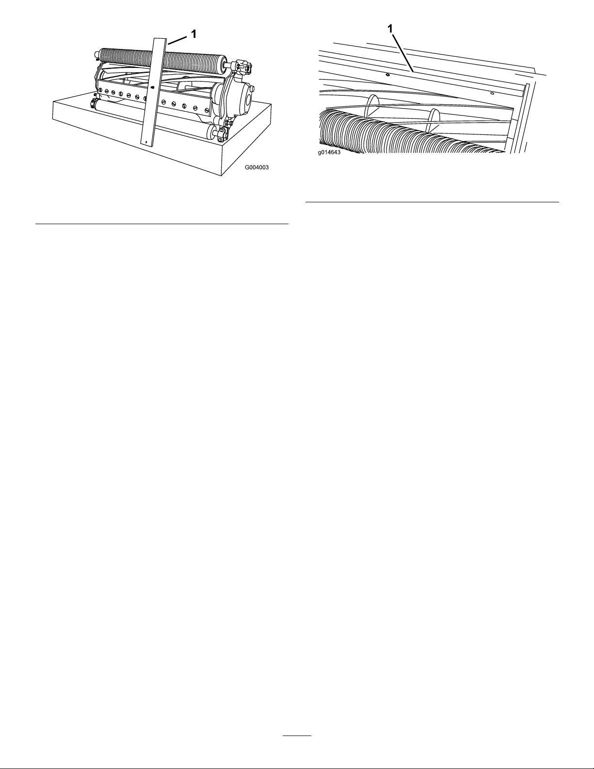
g004003
Figure19
1.Gaugebar
3.Rotatetheadjustingboltuntiltherollercontacts
thefrontofthegaugebar.
4.Repeatsteps2and3fortheleftside.
5.Adjustbothendsoftherolleruntiltheentire
rollerisparalleltothebedknife.
Important:Whensetproperly,therear
andfrontrollerswillcontactthegauge
barandtheboltwillbesnugagainstthe
bedknife.Thisensuresthattheheightofcut
isidenticalatbothendsofthebedknife.
6.Tightenthenutstosecuretheadjustment
enoughtoremoveplayfromthewasher.
7.Verifythattheheight-of-cutsettingiscorrect;
repeatthisprocedureifnecessary.
AdjustingtheCut-OffBar
Adjustthecut-offbartoensurethattheclippingsare
cleanlydischargedfromthereelarea,asfollows:
Note:Thebarisadjustabletocompensatefor
changesinturfconditions.Adjustthebarcloserto
thereelwhentheturfisextremelydry.Bycontrast,
adjustthebarfurtherawayfromthereelwhentheturf
conditionsarewet.Thebarshouldbeparalleltothe
reeltoensureoptimumperformance.Adjustitafter
thereelissharpenedonareelgrinder.
1.Loosentheboltssecuringthetopbar(Figure
20)tothecuttingunit.
g014643
Figure20
1.Cut-offbar
2.Inserta1.5mm(0.060inch)feelergauge
betweenthetopofthereelandthebarthen
tightenthebolts.
Important:Ensurethatthebarandreelare
equaldistanceapartacrossthecomplete
reel.
Note:Adjustthegapasneededforyourturf
conditions.
ServicingtheBedbar
Onlyaproperlytrainedmechanicshouldservicethe
bedbarandbedknifetopreventdamagetothereel,
bedbar,orbedknife.Ideally,takethecuttingunitto
yourauthorizedT orodistributorforservice.Referto
theServiceManualforyourtractionunitforcomplete
instructions,specialtools,anddiagramsforservicing
thebedknife.Shouldyoueverneedtoremove
orassemblethebedbaryourself,instructionsare
providedbelow,asarethespecicationsforservicing
thebedknife.
Important:Alwaysfollowthebedknife
proceduresdetailedinyourServiceManualwhen
servicingthebedknife.Failuretoinstallandgrind
thebedknifecorrectlycanleadtodamagetothe
reel,bedbar,orbedknife.
13
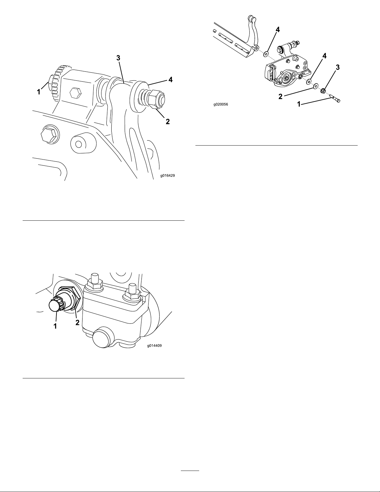
RemovingtheBedbar
1.Turnthebedbaradjustingscrew,
counterclockwise,tobackthebedknife
awayfromthereel(Figure21).
g016429
Figure21
1.Bedbar-adjustingscrew3.Bedbar
2.Spring-tensionnut4.Washer
2.Backoutthespring-tensionnutuntilthewasher
isnolongertensionedagainstthebedbar
(Figure21).
3.Oneachsideofthemachine,loosenthelocknut
securingthebedbarbolt(Figure22).
g014409
Figure22
1.Bedbarbolt2.Locknut
4.Removeeachbedbarboltallowingthebedbar
tobepulleddownwardandremovedfromthe
cuttingunit(Figure22).
Accountforthe2nylonwashersand1steel
washeroneachendofthebedbar(Figure23).
g020056
Figure23
1.Bedbarbolt3.Nylonwasher
2.Nut4.Steelwasher
AssemblingtheBedbar
1.Installthebedbar,positioningthemountingears
betweenthewashersandthebedbar-adjusting
screw(Figure21).
2.Securethebedbartoeachsideplatewiththe
bedbarbolts(nutsonbolts)and3washers(6
total).
3.Positionanylonwasheroneachsideofthe
side-plateboss.Placeasteelwasheroutside
eachofthenylonwashers(Figure23).
4.Torquethebedbarboltsto27to36N∙m(240to
320inch-lb).
5.Tightenthelocknutsuntilyouremovetheend
playfromsteelwashers,butyouareableto
rotatethembyhand.Thewashersontheinside
mayhaveagap.
Important:Donotovertightenthelocknuts
ortheywilldeectthesideplates.
6.Tightenthespringtensionnutuntilthespringis
collapsed,thenbackitoff1/2turn(Figure24).
14

g016470
Figure24
1.Spring-tensionnut2.Spring
7.Adjustthebedknifetothereel;refertoAdjusting
theBedknife-to-ReelContact(page9).
CheckingtheTopGrind
Angle
Theanglethatyouusetogrindyourbedknivesis
veryimportant.
Usetheangleindicatorandtheangle-indicatormount
tochecktheanglethatyourgrinderproducesand
thencorrectforanygrinderinaccuracy.
1.Placetheangleindicatoronthebottomsideof
thebedknifeasshowninFigure25.
g034113
Figure25
1.Bedknife(vertical)2.Angleindicator
2.PresstheAltZerobuttonontheangleindicator.
3.Placetheangle-indicatormountontheedge
ofthebedknifesothattheedgeofthemagnet
mateswiththeedgeofthebedknife(Figure26).
Note:Thedigitaldisplayshouldbevisiblefrom
thesamesideduringthisstepasitwasinstep1.
g034114
Figure26
1.Angle-indicatormount3.Bedknife
2.Edgeofthemagnetmated
withtheedgeofthe
bedknife
4.Angleindicator
4.Placetheangleindicatoronthemountasshown
inFigure26.
Note:Thisistheanglethatyourgrinder
produces,andshouldbewithin2degreesofthe
recommendedtopgrindangle.
ReelGrinding
Specications
ReelDiameter(New)128.5mm(5.06inches)
ServiceLimit-ReelDiameter114.3mm(4.50inches)
ReelShaftDiameter(OD)34.9mm(1.375inches)
BladeReliefAngle30°
BladeReliefAngleRange28–32°
BladeLandWidth1mm(0.040inch)
BladeLandWidthRange0.8to1.2mm(0.030to0.050
inch)
ServiceLimit-ReelDiameter
Taper
0.25mm(0.010inch)
15

InstallingtheBedknife
1.Removetherust,scale,andcorrosionfromthe
bedbarsurfaceandapplyathinlayerofoilto
thebedbarsurface.
2.Cleanthescrewthreads.
3.Applythread-lockingcompoundtothescrews
andinstallthebedknifetothebedbar.
g255045
Figure27
1.Bedbar3.Screw
2.Bedknife
4.Torquethe2outerscrewsto1N∙m(10in-lb).
5.Workingformthecenterofthebedknife,torque
thescrewsto23to28N∙m(200to250in-lb).
g255046
Figure28
1.Bednifescrewtool3.Torqueto23to28N∙m
(200to250in-lb).
2.Installandtorquethese
rstto1N∙m(10in-lb).
6.Grindthebedknife.
BedknifeSpecications
BedknifeScrews
Torque:23to28N∙m(200to250in-lb)
Installationtool:TOR510880
Installationorder:
g254874
Figure29
BedknifeGrindingSpecications
g032182
Figure30
1.Reliefangle4.Frontface
2.Topface5.Frontangle
3.Removeburr
16

Standardbedknifereliefangle3°minimum
Extendedbedknifereliefangle7°minimum
FrontAngleRange13°to17°
BacklappingtheCutting
Unit
DANGER
Contactwiththereelorothermovingparts
canresultinpersonalinjury.
Keepyourngers,hands,andclothingaway
fromthereelsorothermovingparts.
•Stayawayfromthereelwhilebacklapping.
•Neveruseashorthandledpaintbrush
forbacklapping.PartNo.29-9100Handle
assemblycompleteorindividualpartsare
availablefromyourlocalauthorizedToro
distributor.
1.Positionthemachineonaclean,levelsurface,
lowerthecuttingunits,stoptheengine,engage
theparkingbrake,andremovetheignitionkey.
2.Removethereelmotorsfromthecuttingunits
anddisconnectandremovethecuttingunits
fromtheliftarms.
3.Connectthebacklappingmachinetothecutting
unitbyinsertingapieceof3/8inchsquarestock
intothesplinedcouplingintheendofthecutting
unit.
Note:Additionalinstructionsandprocedures
onBacklappingareavailableinyourtraction
unitOperator’sManualandtheToroSharpening
ReelandRotaryMowersManual,FormNumber
80-300PT.
Note:Forabettercuttingedge,runale
acrossthefrontfaceofthebedknifeandreel
whenthelappingoperationiscompleted.This
willremoveanyburrsorroughedgesthatmay
havebuiltuponthecuttingedge.
17

Notes:

DeclarationofIncorporation
TheT oroCompany,8111LyndaleAve.South,Bloomington,MN,USAdeclaresthatthefollowingunit(s)
conform(s)tothedirectiveslisted,wheninstalledinaccordancewiththeaccompanyinginstructionsontocertain
ToromodelsasindicatedontherelevantDeclarationsofConformity.
ModelNo.SerialNo.ProductDescriptionInvoiceDescriptionGeneralDescriptionDirective
04652316000001andUp8-BladeDPAReelMower8BLADECUTTINGUNIT
NGDPA8-BladeDPAReelMower2006/42/EC,
2000/14/EC
04654316000001andUp11-BladeDPAReelMower11BLADECUTTING
UNITNGDPA11-BladeDPAReelMower2006/42/EC,
2000/14/EC
04656316000001andUp14-BladeDPAReelMower14BLADECUTTING
UNITNGDPA14-BladeDPAReelMower2006/42/EC,
2000/14/EC
RelevanttechnicaldocumentationhasbeencompiledasrequiredperPartBofAnnexVIIof2006/42/EC.
Wewillundertaketotransmit,inresponsetorequestsbynationalauthorities,relevantinformationonthispartly
completedmachinery.Themethodoftransmissionshallbeelectronictransmittal.
ThismachineryshallnotbeputintoserviceuntilincorporatedintoapprovedToromodelsasindicatedonthe
associatedDeclarationofConformityandinaccordancewithallinstructions,wherebyitcanbedeclaredin
conformitywithallrelevantDirectives.
Certied:AuthorizedRepresentative:
MarcelDutrieux
ManagerEuropeanProductIntegrity
ToroEuropeNV
Nijverheidsstraat5
2260Oevel
Belgium
JohnHeckel
Sr.EngineeringManagerTel.+3216386659
8111LyndaleAve.South
Bloomington,MN55420,USA
May9,2018

TheToroWarranty
ATwo-YearLimitedWarranty
ConditionsandProductsCovered
TheToroCompanyanditsafliate,ToroWarrantyCompany,pursuant
toanagreementbetweenthem,jointlywarrantyourT oroCommercial
product(“Product”)tobefreefromdefectsinmaterialsorworkmanship
fortwoyearsor1500operationalhours*,whicheveroccursrst.This
warrantyisapplicabletoallproductswiththeexceptionofAerators
(refertoseparatewarrantystatementsfortheseproducts).Wherea
warrantableconditionexists,wewillrepairtheProductatnocosttoyou
includingdiagnostics,labor,parts,andtransportation.Thiswarranty
beginsonthedatetheProductisdeliveredtotheoriginalretailpurchaser.
*Productequippedwithanhourmeter.
InstructionsforObtainingWarrantyService
YouareresponsiblefornotifyingtheCommercialProductsDistributoror
AuthorizedCommercialProductsDealerfromwhomyoupurchasedthe
Productassoonasyoubelieveawarrantableconditionexists.Ifyouneed
helplocatingaCommercialProductsDistributororAuthorizedDealer,or
ifyouhavequestionsregardingyourwarrantyrightsorresponsibilities,
youmaycontactusat:
ToroCommercialProductsServiceDepartment
ToroWarrantyCompany
8111LyndaleAvenueSouth
Bloomington,MN55420-1196
952–888–8801or800–952–2740
E-mail:[email protected]
OwnerResponsibilities
AstheProductowner,youareresponsibleforrequiredmaintenanceand
adjustmentsstatedinyourOperator'sManual.Failuretoperformrequired
maintenanceandadjustmentscanbegroundsfordisallowingawarranty
claim.
ItemsandConditionsNotCovered
Notallproductfailuresormalfunctionsthatoccurduringthewarranty
periodaredefectsinmaterialsorworkmanship.Thiswarrantydoesnot
coverthefollowing:
•Productfailureswhichresultfromtheuseofnon-T ororeplacement
parts,orfrominstallationanduseofadd-on,ormodiednon-T oro
brandedaccessoriesandproducts.Aseparatewarrantymaybe
providedbythemanufactureroftheseitems.
•Productfailureswhichresultfromfailuretoperformrecommended
maintenanceand/oradjustments.Failuretoproperlymaintainyour
ToroproductpertheRecommendedMaintenancelistedinthe
Operator’sManualcanresultinclaimsforwarrantybeingdenied.
•ProductfailureswhichresultfromoperatingtheProductinanabusive,
negligent,orrecklessmanner.
•Partssubjecttoconsumptionthroughuseunlessfoundtobedefective.
Examplesofpartswhichareconsumed,orusedup,duringnormal
Productoperationinclude,butarenotlimitedto,brakepadsand
linings,clutchlinings,blades,reels,rollersandbearings(sealedor
greasable),bedknives,sparkplugs,castorwheelsandbearings,tires,
lters,belts,andcertainsprayercomponentssuchasdiaphragms,
nozzles,andcheckvalves,etc.
•Failurescausedbyoutsideinuence.Conditionsconsideredtobe
outsideinuenceinclude,butarenotlimitedto,weather,storage
practices,contamination,useofunapprovedfuels,coolants,lubricants,
additives,fertilizers,water,orchemicals,etc.
•Failureorperformanceissuesduetotheuseoffuels(e.g.gasoline,
diesel,orbiodiesel)thatdonotconformtotheirrespectiveindustry
standards.
•Normalnoise,vibration,wearandtear,anddeterioration.
•Normal“wearandtear”includes,butisnotlimitedto,damagetoseats
duetowearorabrasion,wornpaintedsurfaces,scratcheddecalsor
windows,etc.
Parts
Partsscheduledforreplacementasrequiredmaintenancearewarranted
fortheperiodoftimeuptothescheduledreplacementtimeforthatpart.
Partsreplacedunderthiswarrantyarecoveredforthedurationofthe
originalproductwarrantyandbecomethepropertyofT oro.Torowillmake
thenaldecisionwhethertorepairanyexistingpartorassemblyorreplace
it.Toromayuseremanufacturedpartsforwarrantyrepairs.
DeepCycleandLithium-IonBatteryWarranty:
DeepcycleandLithium-Ionbatterieshaveaspeciedtotalnumberof
kilowatt-hourstheycandeliverduringtheirlifetime.Operating,recharging,
andmaintenancetechniquescanextendorreducetotalbatterylife.Asthe
batteriesinthisproductareconsumed,theamountofusefulworkbetween
chargingintervalswillslowlydecreaseuntilthebatteryiscompletelyworn
out.Replacementofwornoutbatteries,duetonormalconsumption,
istheresponsibilityoftheproductowner.Batteryreplacementmaybe
requiredduringthenormalproductwarrantyperiodatowner’sexpense.
Note:(Lithium-Ionbatteryonly):ALithium-Ionbatteryhasapartonly
proratedwarrantybeginningyear3throughyear5basedonthetime
inserviceandkilowatthoursused.RefertotheOperator'sManualfor
additionalinformation.
MaintenanceisatOwner’sExpense
Enginetune-up,lubrication,cleaningandpolishing,replacementoflters,
coolant,andcompletingrecommendedmaintenancearesomeofthe
normalservicesToroproductsrequirethatareattheowner’sexpense.
GeneralConditions
RepairbyanAuthorizedToroDistributororDealerisyoursoleremedy
underthiswarranty.
NeitherTheToroCompanynorToroWarrantyCompanyisliablefor
indirect,incidentalorconsequentialdamagesinconnectionwiththe
useoftheToroProductscoveredbythiswarranty,includingany
costorexpenseofprovidingsubstituteequipmentorserviceduring
reasonableperiodsofmalfunctionornon-usependingcompletion
ofrepairsunderthiswarranty.ExceptfortheEmissionswarranty
referencedbelow,ifapplicable,thereisnootherexpresswarranty.All
impliedwarrantiesofmerchantabilityandtnessforusearelimitedto
thedurationofthisexpresswarranty.
Somestatesdonotallowexclusionsofincidentalorconsequential
damages,orlimitationsonhowlonganimpliedwarrantylasts,sotheabove
exclusionsandlimitationsmaynotapplytoyou.Thiswarrantygivesyou
speciclegalrights,andyoumayalsohaveotherrightswhichvaryfrom
statetostate.
Noteregardingenginewarranty:
TheEmissionsControlSystemonyourProductmaybecoveredby
aseparatewarrantymeetingrequirementsestablishedbytheU.S.
EnvironmentalProtectionAgency(EPA)and/ortheCaliforniaAirResources
Board(CARB).Thehourlimitationssetforthabovedonotapplytothe
EmissionsControlSystemWarranty.RefertotheEngineEmissionControl
WarrantyStatementsuppliedwithyourproductorcontainedintheengine
manufacturer’sdocumentationfordetails
CountriesOtherthantheUnitedStatesorCanada
CustomerswhohavepurchasedT oroproductsexportedfromtheUnitedStatesorCanadashouldcontacttheirToroDistributor(Dealer)toobtain
guaranteepoliciesforyourcountry,province,orstate.IfforanyreasonyouaredissatisedwithyourDistributor'sserviceorhavedifcultyobtaining
guaranteeinformation,contacttheToroimporter.374-0253RevD
This manual suits for next models
7
Table of contents
Other Toro Cutter manuals


Popular Cutter manuals by other brands


Cembre
Cembre B-TC650NA Operation and maintenance manual

EFA
EFA Z28S Operating Instructions, Maintenance instructions, Spare Part List

Kasanova
Kasanova GRA-TECH WIS000001-2 user manual

HSGM
HSGM HSG-00-VW operating instructions

Battipav
Battipav Queen 180 operating instructions

Westfalia
Westfalia 82 64 28 instruction manual