Toro TR-34D User manual

FormNo.3393-253RevA
TR-34DTrenchRoller
ModelNo.68039—SerialNo.315000001andUp
G018845
Registeratwww.Toro.com.
OriginalInstructions(EN)*3393-253*A

WARNING
CALIFORNIA
Proposition65Warning
Thisproductcontainsachemicalorchemicals
knowntotheStateofCaliforniatocausecancer,
birthdefects,orreproductiveharm.
Dieselengineexhaustandsomeofits
constituentsareknowntotheStateof
Californiatocausecancer,birthdefects,
andotherreproductiveharm.
Important:Thisengineisnotequippedwithaspark
arrestermufer.ItisaviolationofCaliforniaPublic
ResourceCodeSection4442touseoroperatetheengine
onanyforest-covered,brush-covered,orgrass-covered
land.Otherstatesorfederalareasmayhavesimilarlaws.
Introduction
Thismachineisintendedforuseinvarioussoilconditionsfor
landscapingandconstructionwork.Itisdesignedtoperform
acompactingsoil,andallowsfordirectioncontrolorremote
controluse.
Readthisinformationcarefullytolearnhowtooperateand
maintainyourproductproperly,andtoavoidinjuryand
productdamage.Youareresponsibleforoperatingthe
productproperlyandsafely.
YoumaycontactTorodirectlyatwww .Toro.comforproduct
andaccessoryinformation,helpndingadealer,ortoregister
yourproduct.
Wheneveryouneedservice,genuineToroparts,oradditional
information,contactanAuthorizedServiceDealerorToro
CustomerServiceandhavethemodelandserialnumbersof
yourproductready.Figure1identiesthelocationofthe
modelandserialnumbersontheproduct.Writethenumbers
inthespaceprovided.
G018852
1
Figure1
1.Modelandserialnumberlocation
ModelNo.
SerialNo.
Figure2showsthelocationoftheidenticationnumberson
radio-controltransmitterandradio-controlreceiver.Writethe
numbersinthespaceprovided.
1185562
1196599
G019139
1
213
Figure2
1.Transmitterserialnumber
tag
3.Radio-controlreceiver
2.Radio-controltransmitter4.Receiverserialnumber
tag
TransmitterSerialNo._____________________________
ReceiverSerialNo._______________________________
©2014—TheToro®Company
8111LyndaleAvenueSouth
Bloomington,MN554202
Contactusatwww.Toro.com.
PrintedintheUSA
AllRightsReserved

Thismanualidentiespotentialhazardsandhassafety
messagesidentiedbythesafetyalertsymbol(Figure3),
whichsignalsahazardthatmaycauseseriousinjuryordeath
ifyoudonotfollowtherecommendedprecautions.
Figure3
1.Safetyalertsymbol
Thismanualuses2wordstohighlightinformation.
Importantcallsattentiontospecialmechanicalinformation
andNoteemphasizesgeneralinformationworthyofspecial
attention.
Contents
Safety...........................................................................4
SafeOperatingPractices...........................................4
StabilityData..........................................................6
SlopeChart............................................................7
TiltChart...............................................................8
SafetyandInstructionalDecals.................................9
ProductOverview.........................................................12
Controls...............................................................13
Specications........................................................20
Operation....................................................................20
SettinguptheMachine............................................20
Pre-startChecklist..................................................21
Fuel......................................................................21
AccessingtheMachine............................................24
EngineOilandHydraulicFluid................................24
StartingandStoppingtheEngine..............................26
StoppingtheMachine.............................................27
UsingtheParkingBrake..........................................28
MovingaNon-functioningMachine.........................30
LiftingtheMachine................................................30
PreparingtheMachineforTransport.........................30
MovingandVibratingOperation..............................31
RecoveringtheMachineAfteraTip-over
Event................................................................34
Maintenance.................................................................38
RecommendedMaintenanceSchedule(s)......................38
PremaintenanceProcedures........................................39
Lubrication...............................................................39
GreasingtheMachine.............................................39
EngineMaintenance..................................................40
ChangingtheEngineOilandFilter...........................40
ServicingtheAirFilter............................................42
EngineHardware...................................................43
FuelSystemMaintenance...........................................44
ReplacingtheFuelFilter/WaterSeparator
Canister.............................................................44
DrainingtheFuelTank...........................................45
FuelLinesandFuelInjectors...................................46
ElectricalSystemMaintenance....................................46
ServicingtheBattery...............................................46
ElectricalandElectronic..........................................48
CoolingSystemMaintenance......................................51
ServicingtheCoolingSystem...................................51
HydraulicSystemMaintenance....................................51
ReplacingtheHydraulicFilter..................................51
ChangingtheHydraulicFluid...................................53
CheckingtheHydraulicLines...................................54
HydraulicandFuelTankAccess...................................54
RemovingtheRight-SidePanel.................................54
InstallingtheRight-SidePanel..................................55
EccentricMaintenance...............................................55
ChangingtheEccentricLubricant.............................55
MaintainingtheIsolators.............................................56
CheckingtheIsolators.............................................56
Cleaning...................................................................57
RemovingDebrisfromtheMachine..........................57
CleaningtheChassis...............................................57
Storage........................................................................58
RemovingtheMachinefromStorage.........................58
Troubleshooting...........................................................59
3

Safety
Improperuseormaintenancebytheoperatororowner
canresultininjury.Toreducethepotentialforinjury,
complywiththesesafetyinstructionsandalways
payattentiontothesafetyalertsymbol,which
means:
Caution
,
W ar ning
,or
Danger
—personalsafety
instruction.Failuretocomplywiththeinstructionmay
resultinpersonalinjuryordeath.
SafeOperatingPractices
Thisproductiscapableofcrushingoramputatinghandsand
feet.Alwaysfollowallsafetyinstructionstoavoidserious
injuryordeath.
WARNING
Engineexhaustcontainscarbonmonoxide,an
odorless,deadlypoisonthatcankillyou.
Donotruntheengineindoorsorinanenclosed
area.
Training
•ReadtheOperator'sManualandothertrainingmaterial.If
theoperator(s)ormechanic(s)cannotreadEnglish,itis
theowner'sresponsibilitytoexplainthismaterialtothem.
•Becomefamiliarwiththesafeoperationoftheequipment,
operatorcontrols,andsafetysigns.
•Alloperatorsandmechanicsshouldbetrained.The
ownerisresponsiblefortrainingtheusers.
•Neverletchildrenoruntrainedpeopleoperateorservice
theequipment.Localregulationsmayrestricttheageof
theoperator.
•Theowner/usercanpreventandisresponsiblefor
accidentsorinjuriesoccurringtohimselforherself,other
peopleordamagetoproperty.
Preparation
•Evaluatetheterraintodeterminetheproperandsafe
actionstoperformthejob.Onlyuseaccessoriesand
attachmentsapprovedbythemanufacturer.
•Wearappropriateclothingincludinghardhat,safety
glasses,longpants,safetyshoes,andhearingprotection.
Longhair,looseclothingorjewelrymaygettangledin
movingparts.
•Inspecttheareawheretheequipmentistobeusedand
removeallobjectssuchastools,buildingmaterials,and
personalitemswhichcanbedamagedbythemachine.
•Useextracarewhenhandlingfuels.Theyareammable
andvaporsareexplosive.
–Useonlyanapprovedcontainerforstoringand
transportingfuel.
–Neverremovethefuelcaporaddfueltothemachine
withtheenginerunning.
–Neveraddfueltothemachineordrainfuelfromthe
machineindoors.
–Allowtheenginetocoolbeforefuelingthemachine.
–Donotsmokewhilefuelingthemachine.
•Checkthattheoperator'spresencecontrols,safety
switches,andshieldsareattachedandfunctioning
properly.Donotoperateunlesstheyarefunctioning
properly.
•Beforecompactingsoil,havetheareamarkedfor
undergroundutilities.
Operation
•Neverrunanengineinanenclosedarea.
•Nevercarrypeopleorequipmentontopofthemachine.
•Onlyoperateingoodlight,keepingawayfromholesand
hiddenhazards.
•Besurealltractioncontrolsareinneutralandparking
brakeisengagedbeforestartingtheengine.
•Slowdownanduseextracareonhillsides.Soilconditions
affectthemachine'sstability.
•Neverparkonahill.
•Neveroperatethemachinewiththevibrationfunction
On,andmovingacrossthesideofahill.
•Donotoperateinstandingwater.
•Donotparkthemachineforanextendedperiodina
trench,ditch,orlow-lyingareathatmightllwithwater.
Liftormovethemachinetoalevel,welldrainedsurface.
•Donotoperateattheedgeofembankmentsorroads
becausethemachinemaytipover.
•Slowdownandusecautionwhenmakingturnsand
crossingroadsandsidewalks.
•Usecarewhenapproachingblindcorners,shrubs,trees,
orotherobjectsthatmayobscurevision.
•Stoponlevelground,engageparkingbrake,shutoffthe
enginebeforeleavingtheoperator'spositionforany
reason.
•Lookbehindanddownbeforebackinguptobesureof
aclearpath.
•Ensurethattheareaisclearofotherpeoplebefore
operatingthemachine.Stopthemachineifanyoneenters
thearea.
•Nevercarrypassengersandensurethattheworkingarea
isclearofbystanders.
•Keepfeetclearofdrums.
•Hearingprotectionisrequiredwhenoperatingthis
equipment.
•Donotoperatethemachineundertheinuenceof
alcoholordrugs.
•Locatethepinchpointareasmarkedonthemachineand
keephandsandfeetawayfromtheseareas.
•Forfootprotection,wearsteeltoeshoesortoepads.
4

•Neveroperatewiththeguardsnotsecurelyinplace.Be
sureallinterlocksareattached,adjustedproperly,and
functioningproperty.
•Donotexceedtheratedoperatingcapacityofthe
machine,asthemachinemaybecomeunstablewhichmay
resultinlossofcontrol.
•Donotchangetheenginegovernorsettingoroverspeed
theengine.
•Usecarewhenloadingorunloadingthemachineintoa
trailerortruck.
•Neverleavethemachinerunningunattended.Always
stoptheengine,settheparkingbrake,andremovethe
keybeforeleaving.
•Neverjerkthecontrols;useasteadymotion.
•Watchfortrafcwhenoperatingnearorcrossing
roadways.
•Donottouchpartswhichmaybehotfromoperation.
Allowthemtocoolbeforeattemptingtomaintain,adjust,
orservice.
•Checkforoverheadclearances(i.e.branches,doorways,
electricalwires)beforedrivingunderanyobjectsanddo
notcontactthem.
•Ensurethatyouoperatethemachineinareaswhere
therearenoobstaclesincloseproximitytotheoperator.
Failuretomaintainadequatedistancefromtrees,walls,
andotherbarriersmayresultininjuryasthemachine
backsupduringoperationiftheoperatorisnotattentive
tothesurroundings.Onlyoperatetheunitinareaswhere
thereissufcientclearancefortheoperatortosafely
maneuvertheproduct.
•Lightningcancausesevereinjuryordeath.Iflightning
isseenorthunderisheardinthearea,donotoperate
themachine;seekshelter.
SlopeOperation
Slopesareamajorfactorrelatedtoloss-of-controland
tip-overaccidents,whichcanresultinsevereinjuryordeath.
Allslopesrequireextracaution.
•Donotparkthemachineonahillsideorslope.
•Ifpossible,avoiddrivingthemachineacrossaslope.
Whencrossingaslopeisnecessary,drivethemachine
straightuptheslope,acrossthetop,andthenstraight
downtheslope.
•Slowdownandusecautionwhenmakingturnsandwhen
changingdirectionsonslopes.
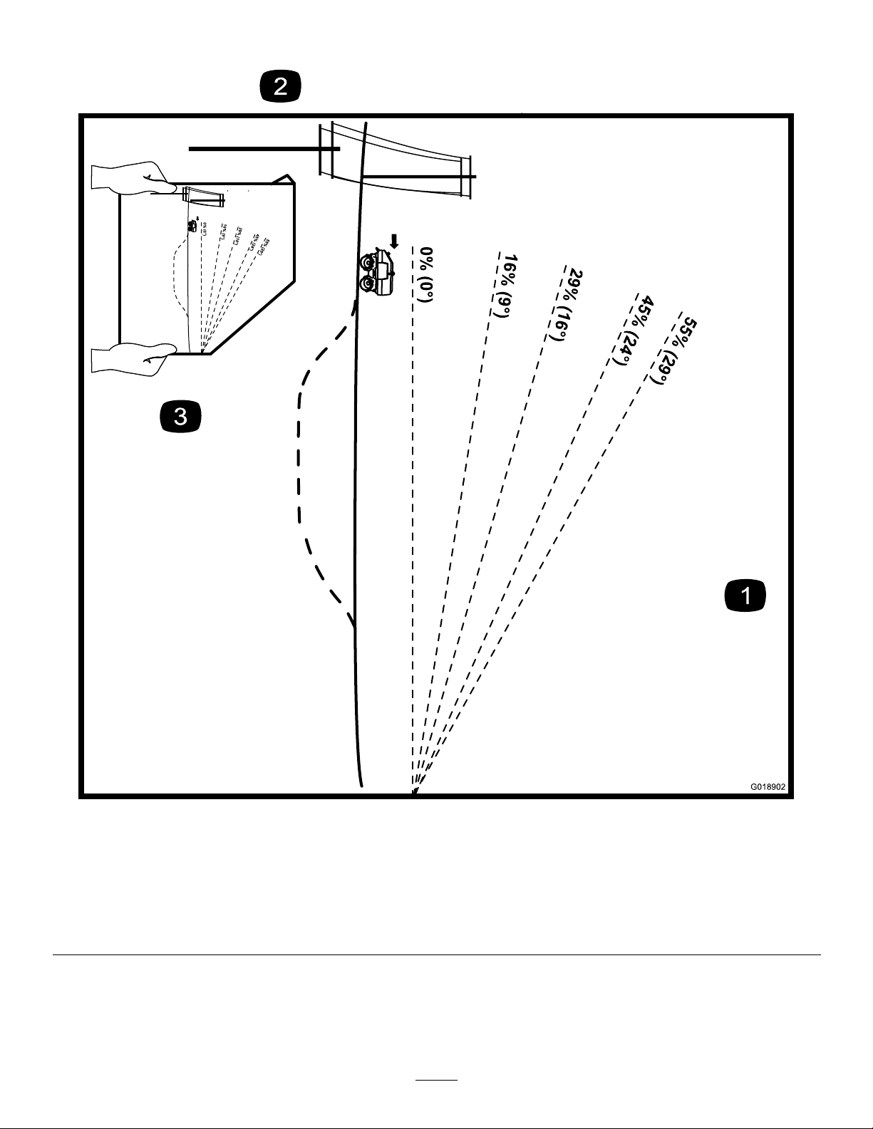
•Donotoperatethemachineonhillsidesorslopes
exceedingtheanglesrecommendedinStabilityData
(page6).SeealsotheSlopeChart(page7)andTiltChart
(page8).
•Neveroperatethemachinewiththevibrationfunction
On,andmovingupordownagradethatisgreaterthan
45percent(24°).
•Neveroperatethemachinewiththevibrationfunction
Off,andmovingupordownagradethatisgreaterthan
55percent(29°).
•Neveroperatethemachinewiththevibrationfunction
Off,andmovingacrossthesideofahillwithagradethat
isgreaterthan18percent(10°).
•Removeobstaclessuchasrocks,treelimbs,etc.fromthe
workarea.Watchforholes,ruts,orbumps,asuneven
terraincouldoverturnthemachine.Tallgrasscanhide
obstacles.
•UseonlyToro-approvedattachments.Attachmentscan
changethestabilityandtheoperatingcharacteristics
ofthemachine.Warrantymaybevoidedifusedwith
unapprovedattachments.
•Avoidstartingorstoppingonaslope.Ifthemachine
losestraction,ensurethatthevibrationfunctionisturned
totheOffpositionandproceedslowly,straightdown
theslope.
•Avoidturningonslopes.Ifyoumustturn,turnslowly.
•Donotoperateneardrop-offs,ditches,orembankments.
Themachinecouldsuddenlyturnoverifadrumgoes
overtheedgeofaclifforditch,orifanedgecavesin.
•Donotoperateonwetgrass.Reducedtractioncould
causesliding.
MaintenanceandStorage
•Parkthemachineonalevelsurface,settheparking
brake,stoptheengine,andremovethekey.Waitforall
movementtostopbeforeadjusting,cleaning,orrepairing.
•Cleandebrisfromthedrives,mufer,andengineto
helppreventres.Cleanupfuel,oil,andhydraulicuid
spillage.
•Lettheenginecoolbeforestoringanddonotstorenear
ame.
•Donotstorefuelnearamesordrainindoors.
•Neverallowuntrainedpersonneltoservicethemachine.
•Usejackstandstosupportcomponentsofthemachine
whenrequired.
•Carefullyreleasepressurefromcomponentswithstored
energy.
•Disconnectthebatterybeforemakinganyrepairs.
Disconnectthenegativeterminalrstandthepositive
last.Reconnectpositiverstandnegativelast.
•Keephandsandfeetawayfrommovingparts.Ifpossible,
donotmakeadjustmentswiththeenginerunning.
•Chargebatteriesinanopenwellventilatedarea,away
fromsparkandames.Unplugthechargerbefore
connectingordisconnectingitfromthebattery.Wear
protectiveclothinganduseinsulatedtools.
•Keepallpartsingoodworkingconditionandallhardware
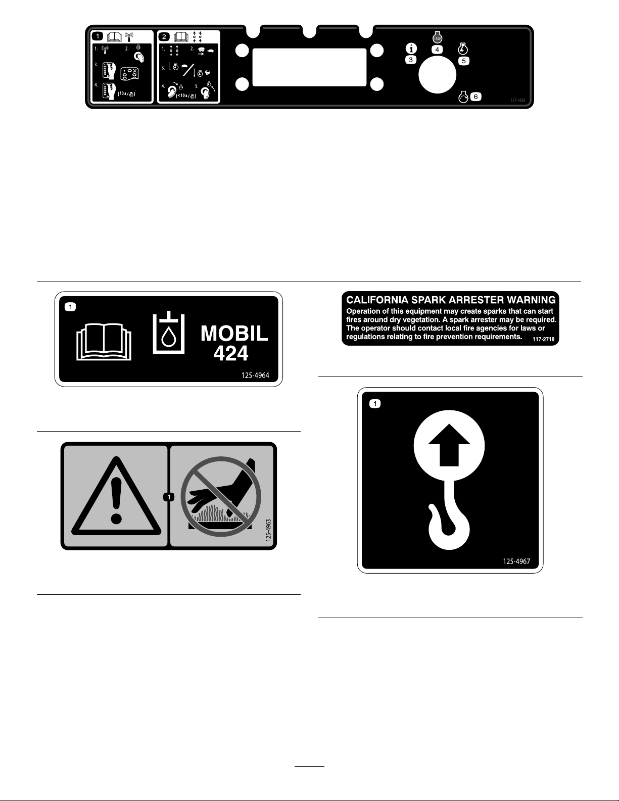
tightened.Replaceallwornordamageddecals.
5

•Nevertamperwithsafetydevices.
•Keepthemachinefreefromthebuildupofmud,rocks,
orotherdebris.Cleanupoilorfuelspillage.Allowthe
machinetocoolbeforestoring.
•Useextracarewhenhandlingfuels.Theyareammable
andvaporsareexplosive.
–Useonlyanapprovedcontainer.
–Neverremovethefuelcaporaddfuelwhenthe
engineisrunning.Allowtheenginetocoolbefore
refueling.Donotsmoke.
–Neverrefuelthemachineindoors.
–Neverstorethemachineorfuelcontainerinside
wherethereisanopename,suchasnearawater
heaterorfurnace.
–Neverllafuelcontainerwhileitisinsideavehicle,
trunk,cargoboxofatruck,oranysurfaceotherthan
theground.
–Keepcontainernozzleincontactwiththetankduring
lling.
•Stopandinspecttheequipmentifyoustrikeanobject.
Makeanynecessaryrepairsbeforerestarting.
•UseonlygenuineTororeplacementpartstoensurethat
originalstandardsaremaintained.
•Batteryacidispoisonousandcancauseburns.Avoid
contactwithskin,eyes,andclothing.Protectyourface,
eyes,andclothingwhenworkingwithabattery.
•Batterygasescanexplode.Keepcigarettes,sparksand
amesawayfromthebattery.
•Keepyourbodyandhandsawayfrompinholeleaks
ornozzlesthatejecthighpressurehydraulicuid.Use
cardboardorpapertondhydraulicleaks;neveruse
yourhands.Hydraulicuidescapingunderpressurecan
penetrateskinandcauseinjuryrequiringsurgerywithina
fewhoursbyaqualiedsurgeonorgangrenemayresult.
StabilityData
Thefollowingtableslistthemaximumsloperecommended
forthemachineinthepositionslistedinthetables.Slopes
overthelisteddegreeinthestabilitydatatablemaycausethe
machinetobecomeunstable.
StabilityDataTable
SlopeOperation
Type:
Operational
Limit:
VibrationOff
Grade(Degrees)
Operational
Limit:
VibrationOn
Grade(Degrees)
Uphill
55%(29°)45%(24°)
Downhill
55%(29°)45%(24°)
Acrossthehill
18%(10°)0%(0°)
6

SlopeChart
0% (0°)
0% (0°)
G018902
Figure4
Thispagemaybecopiedforpersonaluse.
1.Todeterminethemaximumslopeyoucansafelyoperatethemachine,refertotheStabilityDatasection.Usethegradeindicator
todeterminethegradeofinclinebeforeoperating.Donotoperatethismachineonagradegreaterthanthatspeciedinthe
StabilityDatasection.Foldalongtheappropriatelinetomatchtheobservedgrade.
2.Alignthisedgewithaverticalsurfacesuchasautilitypole,tree,building,etc.
3.Exampleofhowtocomparegradewithfoldededge.
Note:Fortiltlimits,refertoFigure5.
7

TiltChart
0% (0°)
G018903
0% (0°)
18% (10°)
Figure5
Thispagemaybecopiedforpersonaluse.
1.Todeterminethemaximumtiltyoucansafelyoperatethemachine,refertotheStabilityDatasection.Usethetiltindicatorto
determinethedegreeofslopebeforeoperating.Donotoperatethismachineonaslopegreaterthanthatspeciedinthe
StabilityDatasection.Foldalongtheappropriatelinetomatchtherecommendedslope.
2.Alignthisedgewithaverticalsurfacesuchasautilitypole,tree,building,etc.
3.Exampleofhowtocompareslopewithfoldededge.
Note:Forslopelimits,refertoFigure4.
8

SafetyandInstructionalDecals
Safetydecalsandinstructionsareeasilyvisibletotheoperatorandarelocatednearanyareaofpotential
danger.Replaceanydecalthatisdamagedorlost.
127–1660
1.Remote-controlmode9.Fast—travelspeed17.Left-reversetraction
2.Manualmode10.Slow—travelspeed18.Right-forwardtraction
3.Warning—emergencystop11.VibrationOn19.Right-reversetraction
4.Pulluptoruntheengine12.Travel-speed/vibration20.Warning—readtheOperator’sManual.
5.Pressdowntostoptheengine13.Fast—enginespeed21.Explosionhazard,fuel—stopthe
engineandextinguishallamesbefore
refueling.
6.Forwardvibration14.Slow—enginespeed22.Warning—wearhearingprotection;
weareyeprotection.
7.Reversevibration15.Enginespeedcontrol23.Warning—keepawayfrommoving
parts;keepguardsandshieldsin
place.
8.Vibrationdirectiontoggle16.Left-forwardtraction24.Warning—keepbystandersawaywhen
operatingthemachine.
9

127–1656
1.ReadtheOperator’sManualforinformationonthe
radio-controlmode—1)Positiontheswitchtotheradio-control
mode;2)Rotatethekeytotheengine-stopposition;3)Press
thelink/startbuttononce—waitfortheactive-linklightto
illuminate;4)Pressthelink/startbuttontostarttheengine.
4.Engine—stop
2.ReadtheOperator’sManualforinformationonthemanual
mode—1)Positiontheswitchtothemanualmode;2)Position
thetractionswitchtoslow;3)Iftheengineiswarm,position
theengine-speedswitchtoslow;iftheengineiscold,
positiontheengine-speedswitchtofast;4)Turnthekeyto
theengine-startpositionfor10secondsorlesstostartthe
engine,thenreleasethekeytotheengine-runposition.
5.Engine—run
3.LEDdisplay6.Engine—start
125–4964
1.ReadtheOperator’sManualforoilinformation.
125–4963
1.Warning—keephandsawayfromhotsurfaces
117–2718
125–4967
1.Liftpoint
10

130–2845
125–8189
1.ReadtheOperator’s
Manualforinformation
onoperatingtheparking
brake.
3.Tosettheparkingbrake,
pulltheknobupslightly,
rotateit90°clockwise,
andthengentlyrelease
theknob.
2.Toreleasetheparking
brake,pulltheknob
upfully,rotateit90°
clockwise,andthengently
releasetheknob.
125–6694
1.Tiedownlocation
125–8187
1.Warning—disconnectthebatterandconsulttheOperator’s
Manualbeforeperformingserviceormaintenanceonthe
machine.
125–8188
1.Warning—readtheOperator’sManualforinformationon
fuses.
11

ProductOverview
Figure6
1.Rearhood8.Right-reardrum15.Eccentricoilplug
2.Liftring9.Parkingbrake16.Left-reardrum
3.Hood-latchhandle10.Isolators17.Drumscraperbar
4.Oil-coolerduct11.Forwardtie-downring18.Reartie-downring
5.Fronthood12.Airinlet19.Safetybar
6.Enginegrill13.Left-frontdrum
7.Controlpanel14.Engine-exhaustpipe
12

Controls
Becomefamiliarwithallthecontrols(Figure7andFigure15)
beforeyoustarttheengineandoperatethemachine.
ControlPanel
STOP
!
!
G018909
7
13
12
11
10 98
5
4
32
6
1
Figure7
1.Keyandkeyswitch8.Right,traction-control
(forward/reverse)
2.Information9.Left,traction-control
(forward/reverse)
3.Engine—stop10.Emergency-stopbutton
4.Engine—run11.Modeswitch
(remote-controlmode|
manualmode)
5.Engine—start12.Vibration-directionswitch
(forward|reverse)
6.LEDdisplay13.Travel-speed/vibration
switch(fast|slow|
vibrationOn)
7.Engine-speedswitch(fast
|slow)
LEDDisplay
Locationandoperation:TheLEDdisplayislocated
onthecontrolpanel.Thedisplayisembeddedintothe
electronicignitioncontrolblock,andiscontrolledthrough
themicroprocessor.Thedisplayprovidestheoperatoror
mechanicoperatinginformationaboutthesystemsonthe
machine.Thefollowingsectiondescribestheinformation
showninthedisplay.
Displaywhilestarting-up—voltage:Duringengine
start-up,thedisplayshowsthebatteryvoltagelevel.Rotatethe
keyswitchtotheStartpositiontodisplaythebatteryvoltage.
Displaywhilerunningthemachine—rpm:Whenthe
engineisrunning,thedisplayshowstheenginerpm.After
startingthemachine,thekeyswitchwillrotatebackto
engine-runpositionandtheenginerpmisindicatedinthe
display.
Displaywhenthekeyswitchisintheinformation
position—hourmeter—faults/warnings—software
version:Toviewoperationinformationforthemachine,
rotatethekeyswitchtotheinformationposition
(counterclockwisefromtheOffposition).
•Hourmeter
•Faultmessages
•Faulthistory
•Warnings
•Softwareversion
Note:Operationinformationisstoredinnonvolatile
memory.Intheeventthatbatterypowerislost,this
informationremainsintact.Uponrestoringbatterypower,
thestoredoperationinformationisavailablefordisplay.
HourMeter
Thehourmeterdisplayindicatesthetotalnumberofhours
themachinehasrun.
RotatethekeyswitchtotheAccessorypositiontodisplay
thehourmeterinformation.
FaultMessages
Thefaultmessagesdenethesituationsthatcausetheengine
ofthemachinetoshutdownornotstart.Thesesafeguards
includeengineprotectcircuitsorothermachineprotection
devices.Faultmessageswillbeshownonthedisplayandwill
indicatewhateventhasshutdowntheengine.
Rotatethekeyswitchtotheinformationpositiontoviewthe
faultmessagesshouldtheyoccur.
•LOWOIL—thismessagedisplayswhentheproperoil
pressureisnotachievedormaintained(monitoredbythe
oilpressureswitch).
•CYLHEADTEMP—thismessagedisplayswhen
thetemperatureofthecylinderheadexceedsthesafe
operatingtemperature(monitoredbythetemperature
switchinthecylinderhead).
•TILT—thismessagedisplayswhenthemachinetipangle
isexceeded(monitoredbythetipswitch).
•ESTOP—thismessagedisplayswhentheemergency
stopbuttononthecontrolpanelisdepressed,andhas
notbeenreset(monitoredbytheemergencystopbutton
position).
Note:TheLEDdisplayalwaysindicatesthelastfault
messagethatoccurred.Thenonvolatilememoryinthe
microprocessoralwaysrequiresaninput,thereforethelast
messagewillbedisplayedevenafterthefaulthasbeen
corrected.
13

FaultHistory
Themicroprocessorrecordsthelast20faultmessagestothe
nonvolatilememory;accessthefaulthistoryasfollows:
1.RotatethekeyswitchtotheInformationpositionto
displaythehourmeter,lastfault,andsoftwareversion
level.
2.Duringthedisplayofthelastfault,quicklyrotatethe
keyswitchtotheOffposition,andthenrotatethekey
switchtotheInformationposition.
Note:Thedisplaywillshowthelast20faults,beginningwith
themostrecent.Toturnoffthedisplayatanytime,turnthe
keyswitchtotheOffposition.
Warnings
Warningmessagesaredenedasmessagesthatindicatethe
electricalsystemisnotoperatingcorrectly.Warningmessages
willashinthedisplaywhenthemachineisrunninginthe
manualoperatormode.The3warningmessagesareas
follows:
Note:IftheVRegLortheBatLowmessageisindicatedin
thedisplay,stoptheengine.IfaVRegLwarningmessageis
indicated,refertoyourEngineOperator'sManual.IfaBatLow
warningmessageisindicated,checkthealternatoroutput
voltageandchargeorreplacethebattery.
•VREG—thevoltageregulatorlowmessageindicatesthat
theelectricalsystemisnotchargingcorrectly.
•BATLOW—thebatterylowmessageindicatesthe
voltagelevelofthebatteryislow.Thismessagewill
displaywhenthebatteryoutputis10voltsorless.
•RPMLOW—therevolutionsperminutelowmessage
indicatestheenginespeedisbelowtheminimumspeed
(monitoredbyalternatoroutput).
SoftwareVersion
Thesoftwareversiondisplayindicatesrevisionlevelofthe
softwareforthemicroprocessor.
Todisplaythesoftwareversioninformation,rotatethekey
switchtotheInformationposition.
KeySwitch
Usethekeyswitchtostartandruntheengine,stopthe
engine,andpowertheaccessorydisplay.Thekeyswitchhas4
positions:Information,Off,Run,andStart.
•Starttheenginebyrotatingthekeyswitchtothe
engine-startposition,andthenreleasingthekeywhen
enginestarts;thekeyitwillmoveautomaticallytothe
engine-runposition(Figure8).
G018951
1 2 34
56
Figure8
1.Information4.Engine—start
2.Engine—Off5.Keyswitch
3.Engine—run6.Key
•Stoptheenginebyrotatingthekeyswitchtothe
engine-Offposition(Figure8).
•Displaythehourmeter,thelastfaultmessage,and
thesoftwareversionbyrotatingthekeyswitchtothe
Informationposition(Figure8).
ModeSwitch
Usethemodeswitchtocontrolthereceptionofcommands
fromtheremote-controltransmitter.Selectingtheswitchto
theradio-controlmodeormanual-modepositionchanges
intendedmachineformofoperation(Figure9).
Important:Prolongthebatterylifeofthemachineby
selectingthemodeswitchtothe
man ual mode
position
whenthemachineisnotinuse.
Note:Selectthemodeswitchtotheradio-controlmode
positiontooperatethemachinewiththeremote-control
transmitter.
Selectthemodeswitchtothemanual-modepositionto
operatethemachinewiththecontrolpanel.
G018947 2
1
Figure9
1.Radio-controlmode2.Manualmode
14

VibrationDirectionSwitch
Usethevibrationdirectionswitchtoselectthedirection
eccentricrotationwhenthevibrationfunctionactive(Figure
10).
2
1
G018948
Figure10
1.Vibrateforward2.Vibratereverse
•Vibrationmovementinaforwarddirection.
•Vibrationmovementinthereversedirection.
Travel-speed/VibrationSwitch
Important:Selecttheslow,travel-speedsettingwhen
movingthemachineinandoutofthetrench,when
loadingthemachineontoatransportvehicle,andwhen
unloadingthemachinefromatransportvehicle.
Usethetravel-speedswitchtocontroltravelspeedofthe
machine(vibrationOff)oractivatethemachine-vibration
function(Figure11).
Note:Thevibrationfunctionisinoperativewhenmoving
themachineinthefast-travelspeedortheslow-travelspeed
settings.
3
1
2
G018949
Figure11
1.Fast-travel(vibration-off)3.VibrationOn(slowtravel)
2.Slow-travel(vibration-off)
Engine-speedSwitch
Usetheengine-speedswitchtochangetheengineRPM
betweentheslowandfast,engine-speedsettings(Figure12).
Important:Performmachineoperationssuchas
movingthemachineandvibrationfunctionswiththe
engine-speedswitchinthefast,engine-speedposition.
2
1
G018950
Figure12
1.Fast,engine-speed2.Slow,engine-speed
EmergencyStopButton
Usetheemergencystopinanysituationwhentheimmediate
stopofthemachineisrequired.Pressingtheemergencystop
buttonwillshutthemachineoffimmediately.
Theemergencystopbuttonislocatedonthecontrolpanel
andislabeled
G021430
belowthered-coloredbutton.
Performthefollowingstepstostopthemachineinan
emergencysituation,andresetthemachinewhenthe
emergency-stopconditioniscorrected:
1.Presstheemergencystopbuttondowntoimmediately
shutoffthemachine(Figure13).
G018946
12
Figure13
1.Emergencystopposition2.Resetfornormaloperation
2.Pulltheemergencystopbuttonuptoresumenormal
machineoperation(Figure13).
15

TractionControls
Movetheleftandright,traction-controlleverstomanually
movethemachineintheforwardorreversedirection
(straight,leftorright)(Figure14).
G019077
1 2
Figure14
RadioSet
Aradiosetisamatchedaddresscodeandradiofrequency
foraradio-controltransmitterandtheradio-controlreceiver.
Theaddresscodesandradiofrequencyfortheradiosetare
unique,andmustmatchforthemachinetofunctionproperly.
Thisrelationshipassuresthatthetransmittercancontrolonly
onereceiver/machine,andthatmultiplecompactorscanbe
usedonthejobsitewithoutinterference.Refertothe7digit
serialnumbersthatyourecordedonpagetitledIntroduction
(Figure2).
Remote-controlTransmitter
Important:Keeptheremote-controltransmitterdry.
Donotpressurewashtheremote-controltransmitter.
ENGINE S P EED
TRAVEL SPEED
R
L
VIB E O N
REV FWD
TRAVEL
G018910
1
2
3
4
5
6
78
9
10
11
12
13
14
Figure15
1.Link/startbutton(green)8.Emergency-stop/power-Off
button
2.Lowbatterylight
(remote-control
transmitter)
9.Fast,engine-speedbutton
(notfunctional)
3.Left,forward-traction
button(uparrow)
10.Forwardvibrationbutton
(vibrationOn)
4.Left,reverse-traction
button(downarrow)
11.Fast,travel-speedbutton
(vibrationOff)
5.Slow,travel-speedbutton
(vibrationOff)
12.Right,reverse-traction
button(downarrow)
6.Reversevibrationbutton
(vibrationOn)
13.Right,forward-traction
button(uparrow)
7.Slow,engine-speedbutton
(notfunctional)
14.Activelinklight(ashes)
Link/StartButton
Pressthelink/startbutton(greenbutton)toestablisharadio
linkbetweentheremote-controltransmitterandtheradio
receiverinthemachineandtostarttheengineinthemachine
(Figure15).
Note:Thelink/startbuttonisthetopbutton(centeredleft
andright)ontheremote-controltransmitter.
Functions:
1.Establishalinktotheradioreceiverofthemachine.
2.Starttheengineofthemachine.
16

Traction-controlButtons
Pressandholdthetraction-controlbuttonstomovethe
machineintheforwardorreversedirection(straight,leftor
right)(Figure15).
Important:Tostopthemovementofthemachine,
releasethetraction-controlbuttons.
•Movethemachineforward.
•Movethemachinebackward.
•Turnthemachineleft.
•Turnthemachineright.
TravelSpeedButtons
Important:Usetheslow-travelspeedsettingwhen
movingthemachineinandoutoftrenches,when
loadingthemachineontoatrailer,andwhenunloading
themachinefromatrailer.
Usethetravelspeedbuttonsontheremote-control
transmittertocontrolthetravelspeedofthemachine
(vibrationOff)oractivatethevibrationfunctionofthe
machine(Figure15).
Note:Thevibrationfunctionisinoperativewhenmovingthe
machineinthefasttravel-speedsettingorslowtravel-speed
setting.
•Movethemachineatminimum-travelspeed.
•Movethemachineatmaximum-travelspeed.
•Stopthevibrationfunction(pressandreleaseeitherthe
sloworfast,travel-speedbutton).
VibrationOnButtons
UsethevibeOnbuttonstoselectthedirectioneccentric
rotationwhenthevibrationfunctionactive(Figure15).
Note:Tostopthevibrationfunctionwiththeremote-control
transmitter,presstheslow,travel-speedbutton;refertoTravel
SpeedButtons(page17).
•Vibrateinaforwarddirection.
•Vibrateinareversedirection.
EngineSpeedButtons
Theengine-speedbuttonsontheremote-controltransmitter
donotfunction.Theenginespeedisautomaticallycontrolled
bythemicroprocessorinthemachinewhenoperatinginthe
remote-controlmode.
Whenthemachineisstartedwiththeremote-control
transmitter,theenginewillstartattheslow-enginespeed,
after1secondtheenginewillautomaticallyacceleratetothe
fast-enginespeedandsustainthatspeed.
Emergency-stop/Power-OffButton
Presstheemergency-stop/power-Offbutton(redbutton)
turnoffthemachineinanemergencysituationorduring
normaloperation(Figure15).
Note:Theemergancy-stop/power-Offbuttonisthebottom
button(centeredleftandright)ontheremote-control
transmitter.
•Turnoffthemachineoffimmediatelyinanemergency
situation.
•Turnoffthemachineduringnormaloperation.
ParkingBrake
Theparkingbrakemechanismisaspringloadedplunger
thatrestsagainstthesurfaceofthedrumwhenthebrakeis
engaged.Usethebrakeknobtoengageanddisengagethe
parkingbrakeofthemachine;refertoUsingtheParking
Brake(page28).
G018954
1
2
454
3
Figure16
1.Brakeknob4.Drumpad
2.Rear,tie-downring5.Plunger
3.Parkingbrake
17

Anti-crushBar
Theanti-crushbarisasafetydevicethatislocatedattherear
ofthemachine,andbelowthecontrolpanel.Whentriggered,
theanti-crushbarpreventsthemachinefromreversetravel
intheeventthattheoperatorbecomesentrappedbehindthe
machine.
G019000
1
Figure17
1.Anti-crushbar
FuelGauge
Thefuelgaugeispartofthefuel-tankcap,andindicatesthe
leveloffuelinthefueltank.
G018967
2
1
3
Figure18
1.Fuel-tankcapandfuel
gauge
3.Fuelgauge
2.Fuel-tankcap
18

Hydraulic-lterGauge
Thehydraulic-ltergaugeindicatesthepressureofhydraulic
uidowingthroughthehydrauliclter.
Thepressurerangesforthehydraulic-ltergaugeareas
follows:
•Normal(green):0to137kPa(0to20PSI)
•Caution(yellow):137to172kPa(20to25PSI)
•Servicethelter(red):172to689kPa(25to100PSI)
G018968
1
1
2
Figure19
1.Hydraulic-lterhousing2.Hydraulic-ltergauge
Hydraulic-tankGauge
Usethehydraulic-tankgaugetoobservethelevelofhydraulic
uidinthetank.Thetankgaugeislocatedontheleft-rear
sideofthehydraulictank.
G018998
1
2
3
Figure20
1.Hydraulic-ltergauge3.Hydraulic-tankgauge
2.Cap/breather
19

Specications
Note:Specicationsanddesignaresubjecttochange
withoutnotice.
Model68039
Width86cm(34inch)
Length167.7cm(66inch)
Height119cm(46.4inch)
Weight1406Kg(3100lb)
Engineoilcapacity0.95L(2qt)
Fuelcapacity11.3L(3USgallon)
Hydraulictankcapacity49L(13USgallon)
VibrationSpecications
DescriptionValue
VibrationFrequency33.3Hz(2000vpm)
CentrifugalForce69.87kN(15709lb)
TotalAppliedForce82.7kN(18609lb)
StaticLinearPressure85N/cm(48psi)
DynamicLinearPressure432N/cm(247psi)
TotalAppliedLinearPressure516N/cm(295psi)
StaticAppliedPadfoot
Pressure
516N/cm(73.06psi)
DynamicAppliedPadfoot
Pressure
127N/cm(370psi)
TotalAppliedPadfoot
Pressure
647.5N/cm(443.3psi)
Operation
Nevermovethemachineacrossaslopegreaterthan
18%grade(10°).
Neverparkthemachineonahill.
Beforestartingthemachine,makesurethatthereareno
personsnearthemachineorobstaclesunderthemachine.
CAUTION
Exposuretoloudnoisecancausehearing
impairmentorloss.
Wearhearprotectionwhenoperatingthemachine.
Important:Usersmustbetrainedtooperatethe
machine.Readthe
Operator’ s Man ual
and
Engine
Owner’ s Man ual.
Learntooperatethemachinesafely.
Important:Beforeoperatingthemachine,checkthe
fuelandoillevel,andremovedebrisfromthemachine.
Ensurethattheareaisclearofpeopleanddebris.You
shouldalsoknowandhavemarkedthelocationsofall
utilitylines.
Note:Determinetheleftandrightsidesofthemachine
fromthenormaloperatingposition.
SettinguptheMachine
ConnectingtheBatteryCable
1.Opentherearhood;refertoAccessingtheMachine
(page24).
2.Verifythetorqueonthepositivecable(Figure21).
Note:Thetorqueshouldbe60to70inch-lb(5to6
ft-lb).
20
Other manuals for TR-34D
2
This manual suits for next models
1
Table of contents
Other Toro Lawn And Garden Equipment manuals

Toro
Toro 68062 User manual

Toro
Toro 07356 User manual

Toro
Toro TransPro 648 User manual

Toro
Toro 44922 User manual

Toro
Toro Wheel Horse 79263 User manual

Toro
Toro Groundsmaster 3280-D User manual

Toro
Toro 04475 User manual

Toro
Toro 108-3654 User manual

Toro
Toro Bullseye QuickGroom 710 User manual

Toro
Toro 30701 User manual