Toro 22673 User manual

Form No. 3464-582 Rev A
Floor Scraper
e-Dingo Compact T ool Carrier
Model No. 22673 —Serial No. 324000000 and Up
Register at www .T oro.com.
Original Instructions (EN)
*3464-582*

W ARNING
CALIFORNIA
Proposition 65 W arning
Use of this product may cause exposure
to chemicals known to the State of
California to cause cancer , birth defects,
or other reproductive harm.
Introduction
The oor scraper is intended to be used on a T oro
compact tool carrier . It is designed to remove
ooring such as vinyl, wood, carpet and other ooring
materials. Using this product for purposes other than
its intended use could prove dangerous to you and
bystanders.
Read this information carefully to learn how to operate
and maintain your product properly and to avoid
injury and product damage. Y ou are responsible for
operating the product properly and safely .
V isit www .T oro.com for more information, including
safety tips, training materials, accessory information,
help nding a dealer , or to register your product.
Whenever you need service, genuine T oro parts, or
additional information, contact an Authorized Service
Dealer or T oro Customer Service and have the model
and serial numbers of your product ready . The model
and serial numbers are located on a plate on the blade
pivot frame. W rite the numbers in the space provided.
Important: W ith your mobile device, you can
scan the QR code on the serial number decal (if
equipped) to access warranty , parts, and other
product information.
g450494
Figure 1
Model No.
Serial No.
This manual identies potential hazards and has
safety messages identied by the safety-alert symbol
(Figure 2 ), which signals a hazard that may cause
serious injury or death if you do not follow the
recommended precautions.
g000502
Figure 2
1. Safety-alert symbol
This manual uses 2 words to highlight information.
Important calls attention to special mechanical
information and Note emphasizes general information
worthy of special attention.
© 2023—The T oro® Company
81 1 1 L yndale A venue South
Bloomington, MN 55420
2
Contact us at www .T oro.com.
Printed in the USA
All Rights Reserved

Contents
Safety . . . . . . . . . . . . . . . . . . . . . . . . . . . . . . . . . . . . . . . . . . . . . . . . . . . . . . . . . . . . . . . . . . . . . . . 3
General Safety . . . . . . . . . . . . . . . . . . . . . . . . . . . . . . . . . . . . . . . . . . . . . . . . . . . 3
Slope Safety . . . . . . . . . . . . . . . . . . . . . . . . . . . . . . . . . . . . . . . . . . . . . . . . . . . . . . . 4
Floor Scraper Safety . . . . . . . . . . . . . . . . . . . . . . . . . . . . . . . . . . . . . . . . . . . 4
Maintenance and Storage Safety . . . . . . . . . . . . . . . . . . . . . . . . 4
Safety and Instructional Decals . . . . . . . . . . . . . . . . . . . . . . . . . . 5
Product Overview . . . . . . . . . . . . . . . . . . . . . . . . . . . . . . . . . . . . . . . . . . . . . . . . . . . . . 6
Specications . . . . . . . . . . . . . . . . . . . . . . . . . . . . . . . . . . . . . . . . . . . . . . . . . . . . 6
Operation . . . . . . . . . . . . . . . . . . . . . . . . . . . . . . . . . . . . . . . . . . . . . . . . . . . . . . . . . . . . . . . . . . 6
Installing and Removing the Attachment . . . . . . . . . . . . . 6
Installing and Removing the Blade
Assembly . . . . . . . . . . . . . . . . . . . . . . . . . . . . . . . . . . . . . . . . . . . . . . . . . . . . . . . . 7
Selecting a Blade . . . . . . . . . . . . . . . . . . . . . . . . . . . . . . . . . . . . . . . . . . . . . . . . 9
Removing Flooring . . . . . . . . . . . . . . . . . . . . . . . . . . . . . . . . . . . . . . . . . . . 10
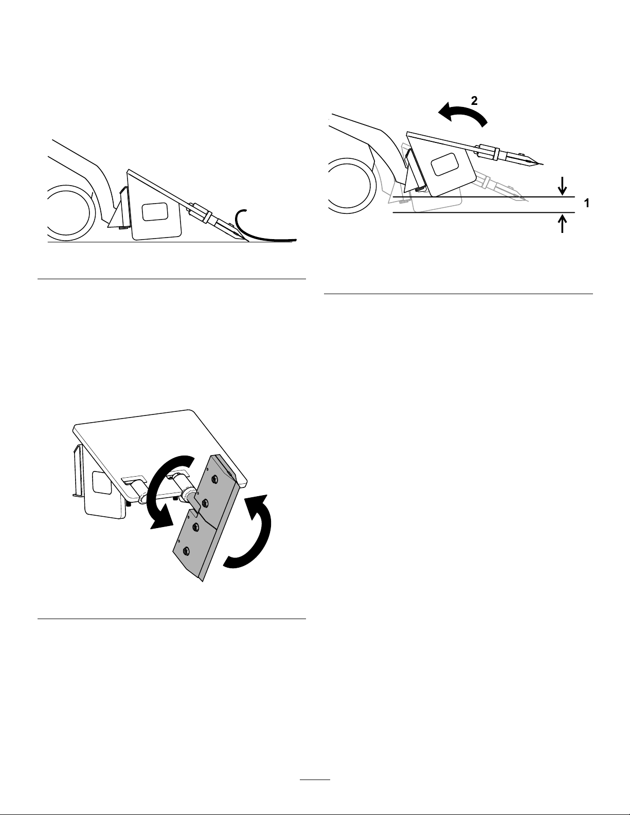
T ransport Position . . . . . . . . . . . . . . . . . . . . . . . . . . . . . . . . . . . . . . . . . . . . 10
Storage . . . . . . . . . . . . . . . . . . . . . . . . . . . . . . . . . . . . . . . . . . . . . . . . . . . . . . . . . . . . . . . . . . . . 1 1
Safety
General Safety
Always follow all safety instructions to avoid serious
injury or death. Using this product for purposes other
than its intended use could prove dangerous to you
and bystanders.
•Do not exceed the rated operating capacity , as the
machine may become unstable, which may result
in loss of control.
•Do not carry a load with the arms raised; always
carry loads close to the ground.
•Slopes are a major factor related to loss-of-control
and tip-over accidents, which can result in severe
injury or death. Operating the machine on any
slope or uneven terrain requires extra caution.
•Operate the machine up and down slopes with
the heavy end of the machine uphill and the
load close to the ground. W eight distribution
changes with attachments. An empty bucket
makes the rear of the machine the heavy end, and
a full bucket makes the front of the machine the
heavy end. Most other attachments make the front
of the machine the heavy end.
•Have the property or work area marked for buried
lines and other objects, and do not dig in marked
areas.
•Read and understand the content of this Operator ’ s
Manual before starting the machine.
•Use your full attention while operating the
machine. Do not engage in any activity that
causes distractions; otherwise, injury or property
damage may occur .
•Never allow children or untrained people to
operate the machine.
•Keep your hands and feet away from the moving
components and attachments.
•Do not operate the machine without the guards
and other safety protective devices in place and
working on the machine.
•Keep bystanders and children out of the operating
area.
•Stop the machine, shut of f the machine, and
remove the key before servicing or unclogging
the machine.
Improperly using or maintaining this machine can
result in injury . T o reduce the potential for injury ,
comply with these safety instructions and always
pay attention to the safety-alert symbol , which
means Caution, W arning, or Danger—personal safety
instruction. Failure to comply with these instructions
may result in personal injury or death.
3

Slope Safety•Operate the machine up and down slopes with
the heavy end of the machine uphill. W eight
distribution changes with attachments. This
attachment makes the front of machine the heavy
end.
•Raising the loader arms on a slope af fects the
stability of the machine. Keep the loader arms in
the lowered position when on slopes.
•Slopes are a major factor related to loss of control
and tip-over accidents, which can result in severe
injury or death. Operating the machine on any
slope or uneven terrain requires extra caution.
•Establish your own procedures and rules for
operating on slopes. These procedures must
include surveying the site to determine which
slopes are safe for machine operation. Always
use common sense and good judgment when
performing this survey .
•Slow down and use extra care on hillsides. Ground
conditions can af fect the stability of the machine.
•A void starting or stopping on a slope. If the
machine loses traction, proceed slowly , straight
down the slope.
•A void turning on slopes. If you must turn, turn
slowly and keep the heavy end of the machine
uphill.
•Keep all movements on slopes slow and gradual.
Do not make sudden changes in speed or
direction.
•If you feel uneasy operating the machine on a
slope, do not do it.
•W atch for holes, ruts, or bumps, as uneven terrain
could overturn the machine. T all grass can hide
obstacles.
•Use caution when operating on wet surfaces.
Reduced traction could cause sliding.
•Evaluate the area to ensure that the ground is
stable enough to support the machine.
•Use caution when operating the machine near the
following:
– Drop-of fs
– Ditches
– Embankments
– Bodies of water
The machine could suddenly roll over if a track
goes over the edge or the edge caves in. Maintain
a safe distance between the machine and any
hazard.
•Do not remove or add attachments on a slope.
•Do not park the machine on a hillside or slope.
Floor Scraper Safety
•W ear cut-resistant gloves and use caution when
installing, removing, or servicing the scraper blade.
•Keep ngers and body parts away from the sharp
edges of the scraper blade.
•Remove the scraper blade before moving or
changing the blade-holder assembly .
Maintenance and Storage
Safety
•Check fasteners at frequent intervals for proper
tightness to ensure that the equipment is in safe
operating condition.
•Refer to this Operator ’ s Manual for important
details if you store the attachment for an extended
period of time.
•Maintain or replace safety and instruction labels,
as necessary .
4

Safety and Instructional Decals
Safety decals and instructions are easily visible to the operator and are located near any area
of potential danger . Replace any decal that is damaged or missing.
decal133-8061
133-8061
decal145-4939
145-4939
1. Thrown object hazard—wear eye protection
4. Cutting hazard of the hand—keep hands away from the
attachment.
2. W arning—keep bystanders away
5. Crushing hazard of hands or feet—keep feet away from the
attachment.
3. W arning—read the Operator ’ s Manual before performing
maintenance.
5

Product Overview
Specications
Note: Specications and design are subject to
change without notice.
Width
71 cm (28 inches)
Length
76 cm (30 inches)
Height
48 cm (19 inches)
W eight
238 kg (525 lb)
T o ensure optimum performance and continued safety
certication of the machine, use only genuine T oro
replacement parts and accessories. Replacement
parts and accessories made by other manufacturers
could be dangerous, and such use could void the
product warranty .
Operation
Determine the left and right sides of the machine from
the normal operating position.
Installing and Removing
the Attachment
Refer to the Operator ’ s Manual for the traction unit for
the installation and removal procedure.
Important: Before installing the attachment,
position the machine on a level surface, ensure
that the mount plates are free of any dirt or debris,
and ensure that the pins rotate freely . If the pins
do not rotate freely , grease them.
Note: Always use the traction unit to lift and move
the attachment.
W ARNING
If you do not fully seat the quick-attach
pins through the attachment mount plate,
the attachment could fall off the machine,
crushing you or bystanders.
Ensure that the quick-attach pins are fully
seated in the attachment mount plate.
6

Installing and Removing
the Blade Assembly
Service Interval : Before each use or daily —Lubricate
the blade-holder assembly shaft.
CAUTION
The blade assembly is heavy . Hands or other
body parts could be crushed.
Use caution when installing the assembly .
W ARNING
The scraper blade is sharp and can cut your
hands.
W ear heavy leather or cut resistant gloves
and move tools away from the blade edge
when installing or removing the blade.
Installing the Blade Assembly
Refer to Selecting a Blade ( page 9 ) to select the
appropriate blade for the application.
1. Park the machine on a level surface.
2. Raise the attachment a few inches of f the
ground for easier access.
3. Engage the parking brake, shut of f the machine,
and remove the key .
4. Lubricate the shaft of the blade-holder assembly ,
then install it into 1 of the 3 tubes on the
attachment. Secure it with a locking pin.
Note: Use the side tubes when removing
ooring close to vertical surfaces, such as walls.
g450495
Figure 3
1. Locking pin 2. Blade-holder assembly
5. Loosen the 4 bolts on the blade-holder clamp
2 turns counterclockwise. Do not remove the
bolts.
W ARNING
Removing the bolts can cause the clamp
to not securely hold the blade, which can
slip and injure you.
Only loosen the bolts; do not remove
them.
g450496
Figure 4
1. Bolt (4)
2. Blade
6. Carefully torque the bolts to 271 N∙m (200 ft-lb).
7

Removing the Blade Assembly
1. Park the machine on a level surface and engage
the parking brake.
2. Raise the attachment a few inches of f the
ground for easier access.
3. Shut of f the machine, and remove the key .
4. Loosen the 4 bolts on the blade-holder clamp 2
turns counterclockwise.
W ARNING
Removing the bolts can cause the clamp
to not securely hold the blade, which can
slip and injure you.
Only loosen the bolts; do not remove
them.
g450498
Figure 5
1. Bolt (4)
2. Blade
5. Remove the blade
6. Remove the locking pin and the blade-holder
assembly .
g450497
Figure 6
1. Locking pin 2. Blade-holder assembly
8

Selecting a Blade
Refer to the table below to select the appropriate blade for the application.
Straight/Flat Blade
Blade with 45°
cutting wings
Blade with 90°
cutting wings
Ceramic Removal
T ool
Heavy
Duty
20 cm 30.5 cm 30.5 cm 61 cm 25 cm 56 cm 25 cm 56 cm
(8 inch) (12 inch) (12 inch) (24 inch) (10 inch) (22 inch) (10 inch) (22 inch)
Single
tooth
Dual
tooth
V inyl tile X X X X
Carpet
squares
X X X X
Carpet
X X
Ceramic
tile
X X X
Quarry tile
X X
Level coat X X
Linoleum X X X X
Rubber
gym oor
X X
W ood oor
X X
Elastomeric
coating
X
Paint X
Epoxy X X
Grease and
grime
X
Asphalt X X X
T ennis
court
surface
X
T rack
surface
X
Glue
X
Mastic X
Striping
X
T ape X
Road
reector
X
T ar paper X
Cork oor
X
Plywood
sub-oor
X X
9

Removing Flooring
1. Fully tilt the attachment rearward and lower the
loader arms. Use this as the starting angle for
scraping the oor .
Note: Using a scraper angle greater than 30
degrees can cause premature wear on the blade
and reduce visibility of the area being scraped.
g450520
Figure 7
2. Drive the traction unit forward to remove ooring.
3. As the blade edge wears, tilt the scraper
attachment in small increments as needed.
Note: If the blade edge becomes dull,
manually rotate the blade-holder assembly 180
degrees to use a new edge. Use the starting
angle described in step 1after rotating the
blade-holder assembly .
g450509
Figure 8
T ransport Position
When transporting the attachment, keep it as close
to the ground as possible, no more than 15 cm (6
inches) above the ground. T ilt it rearward.
g450521
Figure 9
1. No more than 15 cm (6
inches) above the ground
2. T ilt the attachment
rearward.
10

Storage
1. Before long term storage, wash the attachment
with mild detergent and water to remove dirt and
grime.
2. Check the condition of the cutting edge. Remove
and rotate the blade 180 degrees so the worn
edge is on top, if it is badly worn.
3. Check and tighten all bolts, nuts, and screws.
Repair or replace any part that is damaged or
worn.
4. Paint all scratched or bare metal surfaces.
Note: Paint is available from your Authorized
Service Dealer .
5. Store the attachment in a clean, dry garage or
storage area. Cover it to protect it and keep it
clean.
1 1

California Proposition 65 W arning Information
What is this warning?
Y ou may see a product for sale that has a warning label like the following:
W ARNING: Cancer and Reproductive Harm—www .p65W arnings.ca.gov .
What is Prop 65?
Prop 65 applies to any company operating in California, selling products in California, or manufacturing products that may be sold in or brought into
California. It mandates that the Governor of California maintain and publish a list of chemicals known to cause cancer , birth defects, and/or other
reproductive harm. The list, which is updated annually , includes hundreds of chemicals found in many everyday items. The purpose of Prop 65 is to
inform the public about exposure to these chemicals.
Prop 65 does not ban the sale of products containing these chemicals but instead requires warnings on any product, product packaging, or literature with
the product. Moreover , a Prop 65 warning does not mean that a product is in violation of any product safety standards or requirements. In fact, the
California government has claried that a Prop 65 warning “is not the same as a regulatory decision that a product is ‘safe’ or ‘unsafe.’” Many of these
chemicals have been used in everyday products for years without documented harm. For more information, go to https://oag.ca.gov/prop65/faqs-view-all .
A Prop 65 warning means that a company has either (1) evaluated the exposure and has concluded that it exceeds the “no signicant risk level”; or (2)
has chosen to provide a warning based on its understanding about the presence of a listed chemical without attempting to evaluate the exposure.
Does this law apply everywhere?
Prop 65 warnings are required under California law only . These warnings are seen throughout California in a wide range of settings, including but not
limited to restaurants, grocery stores, hotels, schools, and hospitals, and on a wide variety of products. Additionally , some online and mail order
retailers provide Prop 65 warnings on their websites or in catalogs.
How do the California warnings compare to federal limits?
Prop 65 standards are often more stringent than federal and international standards. There are various substances that require a Prop 65 warning
at levels that are far lower than federal action limits. For example, the Prop 65 standard for warnings for lead is 0.5 μg/day , which is well below
the federal and international standards.
Why don’t all similar products carry the warning?
•Products sold in California require Prop 65 labelling while similar products sold elsewhere do not.
•A company involved in a Prop 65 lawsuit reaching a settlement may be required to use Prop 65 warnings for its products, but other companies
making similar products may have no such requirement.
•The enforcement of Prop 65 is inconsistent.
•Companies may elect not to provide warnings because they conclude that they are not required to do so under Prop 65; a lack of warnings for a
product does not mean that the product is free of listed chemicals at similar levels.
Why does T oro include this warning?
T oro has chosen to provide consumers with as much information as possible so that they can make informed decisions about the products they buy and
use. T oro provides warnings in certain cases based on its knowledge of the presence of one or more listed chemicals without evaluating the level of
exposure, as not all the listed chemicals provide exposure limit requirements. While the exposure from T oro products may be negligible or well within the
“no signicant risk” range, out of an abundance of caution, T oro has elected to provide the Prop 65 warnings. Moreover , if T oro does not provide these
warnings, it could be sued by the State of California or by private parties seeking to enforce Prop 65 and subject to substantial penalties.
Rev A
Table of contents
Other Toro Lawn And Garden Equipment manuals

Toro
Toro Bullseye NuSurface 790 User manual

Toro
Toro GreensPro 1240 User manual

Toro
Toro ProCore 648s User manual

Toro
Toro 100 Series Z Master User manual

Toro
Toro 22368 User manual

Toro
Toro 68062 User manual

Toro
Toro 03540 Reelmaster 5200-D User manual

Toro
Toro 3550 User manual

Toro
Toro 99-7019 User manual

Toro
Toro 04358 Greensmaster 3150 User manual