Note:Theshoulderboltshouldnotclampthe
platetothehousing.
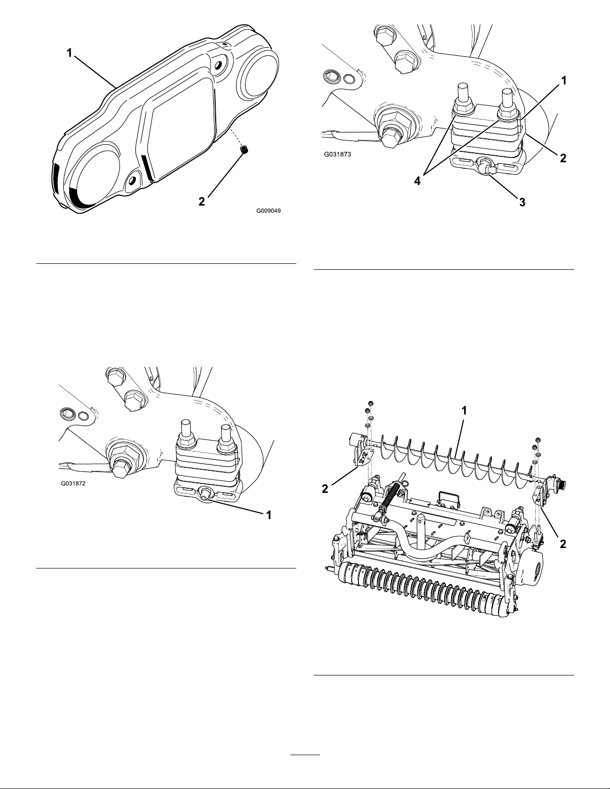
8.Checktoensurethattheroller-brushplateis
paralleltothecutting-unitsideplate.Ifitisnot
parallel,proceedasfollows:
A.Loosenthe2angelocknutssecuring
theroller-brushmountingbrackettothe
cutting-unitsideplate(Figure13).
B.Rotatetheroller-brushbearinghousinguntil
thebrushplateisparalleltothecutting-unit
sideplate(Figure13).
C.Tightenthe2angelocknutssecuring
theroller-brushmountingbrackettothe
cutting-unitsideplate(Figure13).
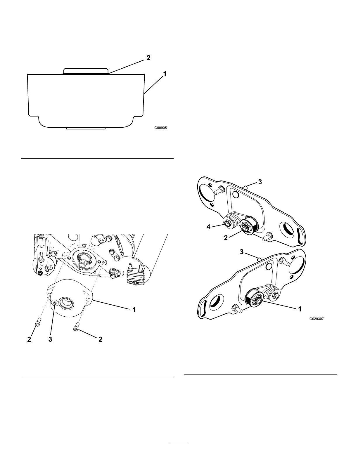
g193249
Figure13
1.Loosentheseboltsforpositioningtherollerbrush.
2.Loosenthesenutsformakingtheroller-brushplateparallel.
PositioningtheRollerBrush
1.Loosenthe2boltssecuringeachroller-brush
bearinghousingtotheroller-brushmounting
bracket(Figure13).
Note:Theboltsshouldbeloosefromthe
factory.
2.Positiontherollerbrushsothatitisjusttouching
orrestingontherearroller(Figure14).
Important:Theroller-brushshaftmustnot
contactthecutting-unitsideplate.
Important:Heavybrushcontactonthe
rollerwillcauseprematurebrushwear.
g027303
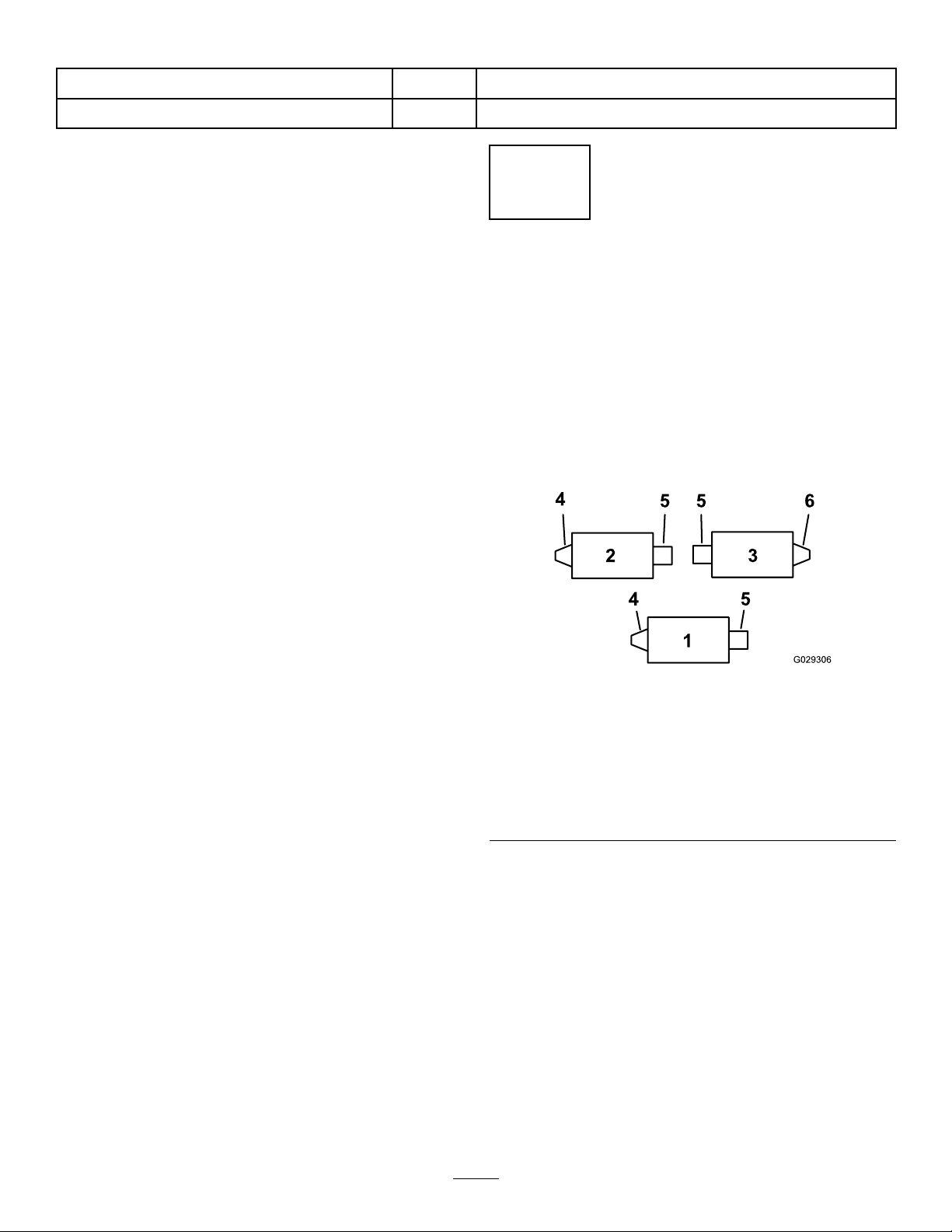
Figure14
1.Bearinghousing(some
partsnotshown)
5.Lightcontact
2.Sideplate6.Rearroller
3.Rollerbrush7.Greasetting
4.Ensurethatthereis
clearancehere.
Note:Theroller-brushshaftmustbeparallel
totherearroller.
Important:Positionbothroller-brush
bearinghousingssothattheyareparallel
tothegroundtoensureclearanceforthe
rear-rollergreasetting.
3.Tightenthe2boltssecuringeachroller-brush
bearinghousingtotheroller-brushmounting
brackets.
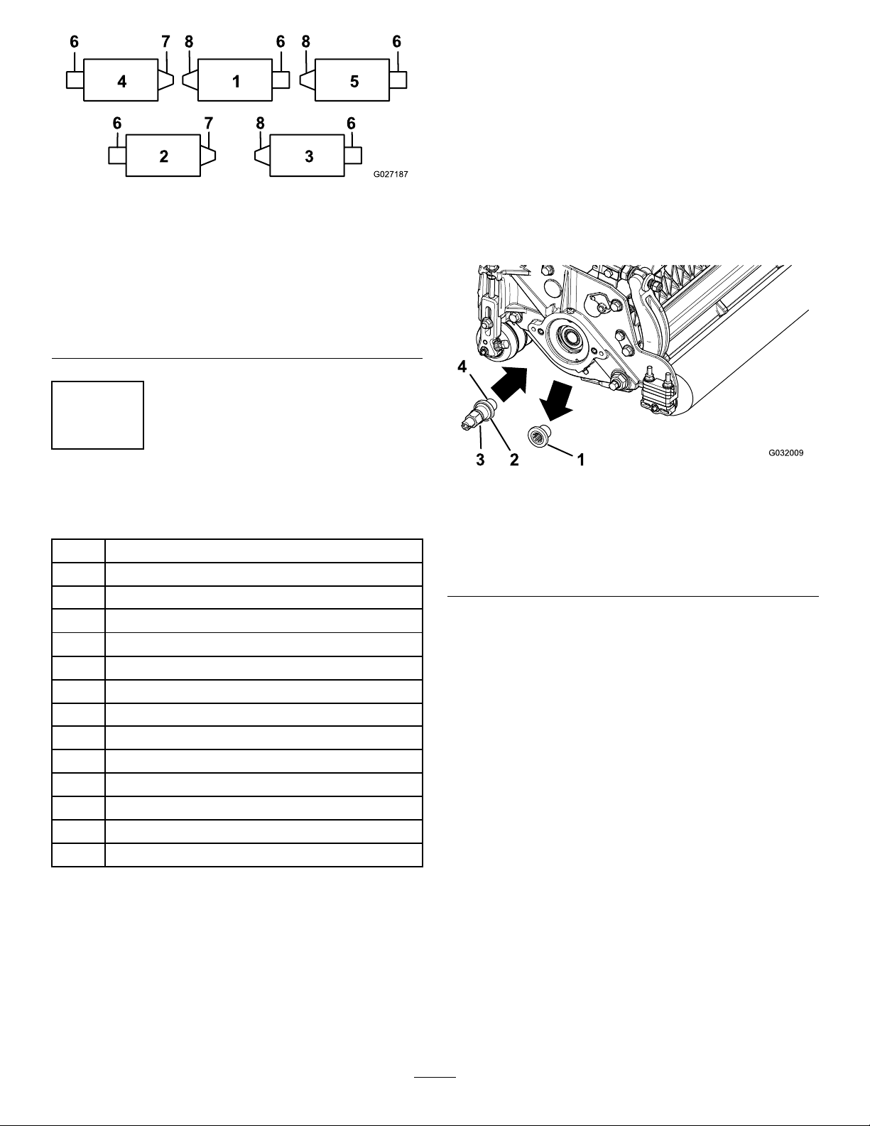
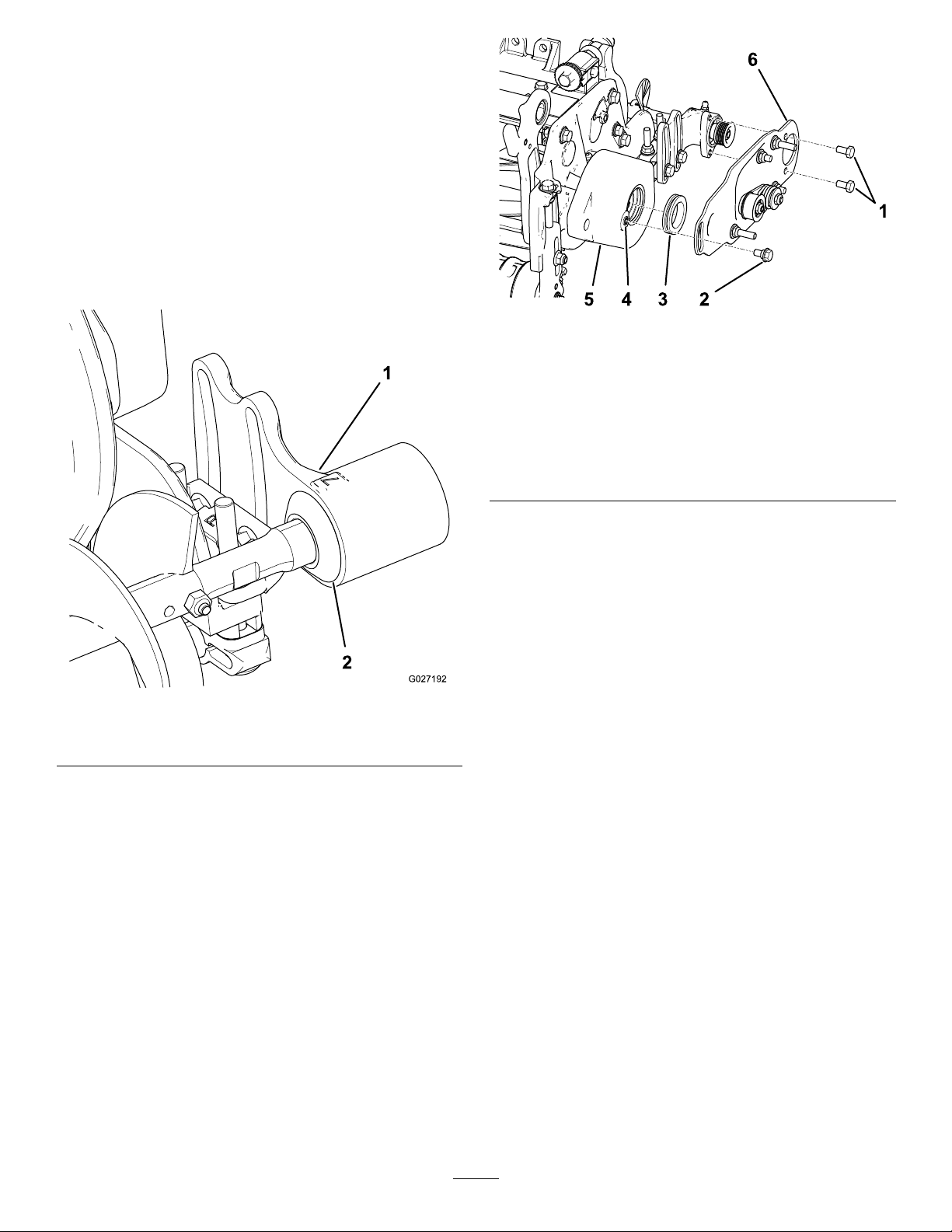
InstallingtheDrivePulley
1.Insertthespacerontotheshaftinthebearing
housing(Figure15).
2.Insertthedrivepulleyintothespacerandonto
thedriveshaft(Figure15).
Note:Ensurethatthepulleytabsarepositioned
intheslotinthedriveshaft.
3.Securethepulleyandspacertothedriveshaft
withaange-headbolt(3/8x2inches);refer
toFigure15.
Note:Torquetheboltto47to54N∙m(35to
40ft-lb).
7