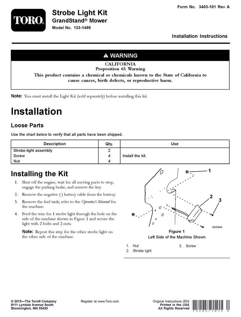
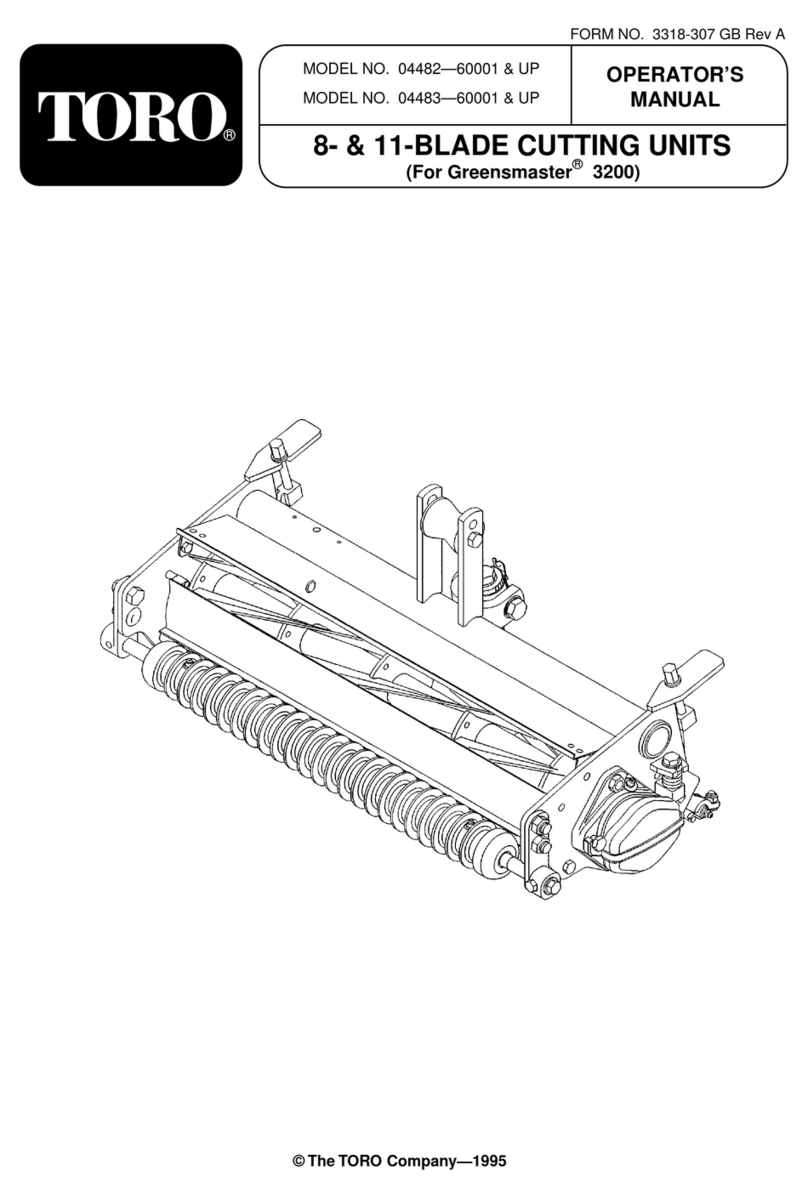
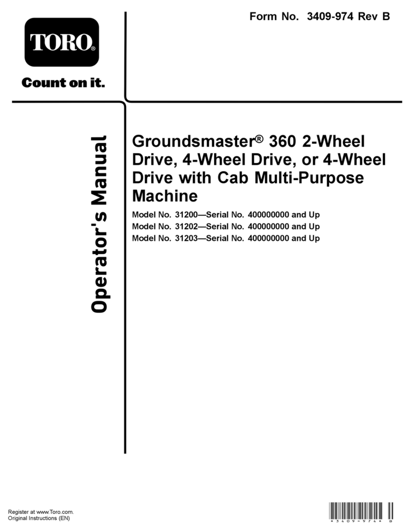
Toro 140-5800 User manual

FormNo.3450-784RevA
ManualFlowDividerKit
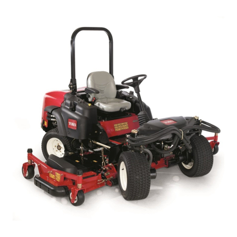
Groundsmaster®5900RotaryMower
ModelNo.140-5800
InstallationInstructions
Note:Determinetheleftandrightsidesofthemachinefromthenormaloperatingposition.
Safety
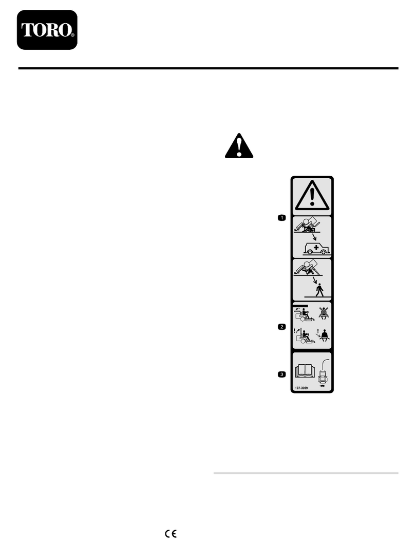
SafetyandInstructionalDecals
Safetydecalsandinstructionsareeasilyvisibletotheoperatorandarelocatednearanyarea
ofpotentialdanger.Replaceanydecalthatisdamagedormissing.
decal140-5833
140-5833
1.Pressfor4-wheeldrive
Installation
LooseParts
Usethechartbelowtoverifythatallpartshavebeenshipped.
ProcedureDescriptionQty.Use
1Nopartsrequired–Preparethemachine.
Momentaryswitch1
Washer(5/8inch)1
Jamnut(5/8inch)1
Decal1
2
WireHarness1
Installthemomentaryswitch.
3Nopartsrequired–Removethecontrolconsolecoverand
electricalpanelcover.
4Nopartsrequired–Installthekitwireharnessatthe
electricalpanel.
©2021—TheToro®Company
8111LyndaleAvenueSouth
Bloomington,MN55420
Registeratwww.T oro.com.OriginalInstructions(EN)
PrintedintheUSA
AllRightsReserved*3450-784*

ProcedureDescriptionQty.Use
Traction-controlvalve1
Coil1
Coilnut1
MOC-LOCfastener1
5
Cabletie1
Installthekitwireharnesstothetraction
manifold.
6Nopartsrequired–Installtheelectrical-paneland
control-consolecovers.
7Nopartsrequired–Finishthekitinstallation.
1
PreparingtheMachine
NoPartsRequired
Procedure
1.Parkthemachineonalevelsurface.
2.Lowerthemowerdecks.
3.Engagetheparkingbrake,shutofftheengine,
removethekey,andwaitforallmovingparts
tostop.
CAUTION
Ifyouleavethekeyintheswitch,
someonecouldaccidentlystartthe
engineandseriouslyinjureyouor
bystanders.
Removethekeyfromtheignitionswitch
beforeyoudoanymaintenance.
4.Openthehood.
5.Rotatethebattery-disconnectswitchtotheOFF
position(Figure1).
g031667
Figure1
1.Battery-disconnectswitch
(OFFposition)
2.Battery-disconnectswitch
(ONposition)
6.Allowtheenginetocooldown.
2

2
InstallingtheMomentary
Switch
Partsneededforthisprocedure:
1Momentaryswitch
1Washer(5/8inch)
1Jamnut(5/8inch)
1Decal
1WireHarness
PreparingtheControlConsole
1.Attheoutboardsideofthecontrolconsole,
removethe5ange-headcapscrewsthatsecure
therightcontrol-consolecover(Figure2).
g320588
Figure2
1.Controlconsolepanel3.Control-consolecover
(right)
2.Flange-headcapscrew
2.Movetheoperator’sseatrearward.
3.Measure289mm(11-3/8inches)fromtheback
oftheoftheconsolearm,andmarkthesurface
oftheleftconsolepanel(Figure3).
g320614
Figure3
4.Measure25mm(1inch)fromthetopoftheof
theconsolearm,andmarkthesurfaceoftheleft
consolepanel(Figure3).
5.Attheintersectionofthemarks,center-punch
theleftconsolepanel.
6.Drillahole—17mm(21/32inch)atthe
center-punchmark(Figure3).
Important:Usecautionwhendrillingthe
consolepanel.
AssemblingtheMomentarySwitch
totheControlConsole
1.Assemblethemomentaryswitchintothehole
leftconsolepanel(Figure4).
3

g320615
Figure4
1.Rightsideofthemachine3.Washer(5/8inch)
2.Momentaryswitch4.Jamnut(5/8inch)
2.Insidethecontrolconsole,securetheswitchto
thepanel(Figure4)withthewasher(5/8inch)
andjamnut(5/8inch).
3.Attheoutboardsideofthecontrolconsole,
adherethedecaltotheleftconsolepanelas
showninFigure5.
g320703
Figure5
1.Decal
ConnectingtheKitWireHarness
totheMomentarySwitch
1.Positionthekitwireharnessbehindtheseatand
controlconsoleasshowninFigure6.
g320701
Figure6
2.Atthebackofthecontrolconsole,route
the2-wirebranch(thebranchwith2
single-receptacleterminals)ofthekitwire
harnessalongtheplatformwireharnessand
intotheconsole(Figure7).
4

g320702
Figure7
1.Machinewireharness5.Frontofthemachine
2.Armsupport6.2single-receptacle
terminals(2-wire
branch—kitwireharness)
3.2-wirebranch(kitwire
harness)
7.Spadeterminals
(momentaryswitch)
4.Supportchannel
3.Assemblethe2single-receptacleterminalsonto
thespadeterminalsofthemomentaryswitch
(Figure7).
3
RemovingtheElectrical
PanelCover
NoPartsRequired
Procedure
1.Movetheoperator’sseatfullyforward.
2.Loosentheknobsthatsecuretheelectrical-panel
covertothemachine,andremovethecover
(Figure8).
g320789
Figure8
1.Knobs3.Electricalplate
2.Electrical-panelcover4.Grommet
4
InstallingtheKitWire
HarnessattheElectrical
Panel
NoPartsRequired
RoutingtheKitWireHarnessto
theElectricalPanel
Routethebranchofthewirekitharnesswiththe
spadeconnectorandthe5-socketconnectoralong
theplatformwireharnessofthemachine,andtoward
thefuseblock(Figure9).
5

g321566
Figure9
1.Spadeconnector(kitwire
harness)
2.5-socketconnector(kit
wireharness)
InstallingtheKitWireHarnessto
theFuseBlock
1.Atthebottomofthefuseblock,locatethewire
attachedtosocketC5oftheblockandremove
theshrink-wrapinsulatorfromtheterminal
receptacle(Figure10).
g321564
Figure10
1.Terminalreceptacle
(optionspower
wire—fuse-blocksocket
C5)
3.Spadeconnector(kitwire
harness)
2.Shrink-wrapinsulator
2.Plugthespadeconnectorofthekitwireharness
(Figure10)intotheterminalreceptacleforthe
optionspowerwire(fuse-blocksocketC5).
3.Insertthefuse(10A)intofuse-blocksocketC5
(Figure11).
6

g321565
Figure11
1.Fuse(10A)2.Fuse-blocksocketC5
InstallingtheRelay
1.Plugtherelayintothe5-socketconnectorofthe
kitwireharness(Figure12).
g321563
Figure12
1.Relay3.Electricalplate
2.5-socketconnector(kit
wireharness)
4.Push-infastener
2.Aligntheholeinthetaboftherelaywiththehole
intheelectricalplate,andsecuretherelaytothe
platewithapush-infastener(Figure12).
5
InstallingtheKitWire
HarnesstotheTraction
Manifold
Partsneededforthisprocedure:
1Traction-controlvalve
1Coil
1Coilnut
1MOC-LOCfastener
1Cabletie
RoutingtheKitWireHarnessto
theTractionManifold
1.Routethe2-pinconnectorandthe2-socket
connectorsalongtheplatformwireharnessand
throughtheholeintherightoorpan(Figure13).
g321568
Figure13
1.Hole(rightoorpan)3.Platformwireharness
2.2-pinconnectorand
2-socketconnectors(kit
wireharness)
2.Routethekitwireharnessdownandtowardthe
tractionmanifold(Figure14).
7

g321582
g321567
Figure14
1.Kitwireharness3.Tractionmanifold
2.Frontofthemachine
InstallingtheCoilandValvetothe
TractionManifold
1.Removetherelief-valvecartridgefromportRV1
ofthetractionmanifold(Figure15).
Note:Loosentherelief-valvecartridgeusing
thehexatsofthevalvebody.
g321606
Figure15
1.PortRV1(traction
manifold)
4.Traction-controlvalve
2.Frontofthemachine5.Coil
3.Relief-valvecartridge6.Coilnut
2.Installthetraction-controlvalveintoportRV1of
thetractionmanifold(Figure15).
Important:Tightenthevalveusingthehex
atsofthevalvebody.
3.Assemblethecoilontothetraction-controlvalve,
andsecurethecoilwiththecoilnut(Figure15).
4.Torquethecoilnutto9.5to13.6N∙m(84to120
in-lb).
ConnectingtheKitWireHarness
totheTractionManifold
1.Removethe2-socketconnectorofthemachine
wireharnesslabeledTRACTIONMOW/TRANSPORT
fromthe2-pinconnectorofthesolenoidvalvein
portSVofthetractionmanifold(Figure16).
8

g321607
Figure16
1.2-pinconnector
(solenoidvalve—traction
manifold-portSV
2.2-socketconnector
(machinewire
harness—labeled
TRACTION
MOW/TRANSPORT)
2.Plugthe90°2-socketconnectorofthekitwire
harnessintothe2-pinconnectorofthesolenoid
valveinportSVofthetractionmanifold(Figure
17).
g321640
Figure17
1.Straight2-socket
connector(kitwire
harness)
4.90°2-socketconnector(kit
wireharness)
2.2-pinconnector
(coil—traction
manifold-portRV1)
5.2-socketconnector
(machinewire
harness—labeled
TRACTION
MOW/TRANSPORT)
3.2-pinconnector
(solenoidvalve—traction
manifold-portSV)
6.2-pinconnector(kitwire
harness)
3.Plugthestraight2-socketconnectorofthekit
wireharnessintothe2-pinconnectorofthecoil
atportRV1ofthetractionmanifold(Figure17).
4.Plugthe2-socketconnectorofthemachine
wireharnesslabeledTRACTIONMOW/TRANSPORT
intothe2-pinconnectorofthekitwireharness
(Figure17).
SecuringtheKitWireHarnessto
theMachine
1.Atthebottomofthemachine,cliptheMOC-LOC
fastenertothetubeconnectingportM7ofthe
tractionmanifoldtotheright,fronttractionmotor,
asshowninFigure18.
9

g321582
g321701
Figure18
1.Tube(traction
manifold-portM7—right,
fronttractionmotor)
3.MOC-LOCfastener
2.Kitwireharness
2.Alignthekitwireharnessthoughtheclampside
oftheMOC-LOCfastener,andsecuretheclamp
aroundtheharness(Figure18).
3.Atthetopofthemachine,securethekitwire
harnesstotheplatformwireharnesswith2
cableties(Figure19)
g321708
g321709
Figure19
1.Cabletie3.Platformwireharness
2.Kitwireharness
6
Installingthe
Electrical-Paneland
Control-ConsoleCovers
NoPartsRequired
Procedure
1.Alignthegrommetsatthebottomofthe
electrical-panelcover(Figure20)withthe2pins
intheoorpanel.
2.Alignthethreadedrodsoftheknobsattached
tothecoverwiththecinchnutsoftheelectrical
plate(Figure20).
10

g320789
Figure20
1.Knobs3.Electricalplate
2.Electrical-panelcover4.Grommet
3.Assemblethecovertotheplateandsecurethe
panelwiththeknobs(Figure20).
4.Attheoutboardsideofthecontrolconsole,align
theholesintherightcontrol-consolecoverwith
theholesintheconsole(Figure21).
g320588
Figure21
1.Controlconsolepanel3.Control-consolecover
(right)
2.Flange-headcapscrew
5.Assemblethecovertothecontrolconsole
(Figure21)withthe5ange-headcapscrews
thatyouremovedinPreparingtheControl
Console(page3).
7
FinishingtheKitInstallation
NoPartsRequired
ConnectingtheBattery
1.Rotatethebattery-disconnectswitchtotheON
position(Figure22).
g031667
Figure22
1.Battery-disconnectswitch
(OFFposition)
2.Battery-disconnectswitch
(ONposition)
2.Closethehoodandsecureitwiththe2hood
latches.
TestingtheTractionSystem
1.Starttheengineanddisengagetheparking
brake.
2.Pressthehigh—lowrange-speedswitchtotheL
(lowrange)position(Figure23)
11

g321711
Figure23
1.High—lowrange-speed
switch
2.Momentaryswitch
3.Pressandholdthemomentaryswitch(Figure
23).
4.Tofeelthe4-wheeldriveismoreaggressive,
slowlydrivethemachineinafullturn.
Note:Youshouldfeelincreasedpowertrain
torqueanditiseasilyfeltonapavedsurface.
5.Whiledrivingthemachineinaturn,releasethe
momentaryswitchtoconrmthatthe4-wheel
drivereturnstoit’snormalmode.
6.Stopthemachine,engagetheparkingbrake,
shutofftheengine,removethekey,andwaitfor
allmovingpartstostop.
Operation
OperatingtheTraction
System
Note:The4-wheeldrivemomentaryswitchengages
amoreaggressive4-wheeldrivemodewhilethe
switchispressed.
1.Stopthemachine.
2.Pressthehigh—lowrange-speedswitchtotheL
(lowrange)position(Figure24).
Important:Donotusethe4-wheeldrive
switchwhilethetractionsystemisinhigh
range.
Note:Onlyusethe4-wheeldriveswitchwhen
necessarytoavoidprematurewearonthe
tractionsystem.
g321711
Figure24
1.High—lowrange-speed
switch
2.4-wheeldriveswitch
3.Pressandholdthe4-wheeldriveswitchto
engageamoreaggressive4-wheeldrive
response(Figure24).
4.Drivethemachinewhilepressingthe4-wheel
driveswitch.
5.Releasethe4-wheeldriveswitchtodrivethe
machineinthenormal4-wheeldrivemode.
12
Table of contents
Other Toro Lawn Mower Accessories manuals