manuals.online logo
Brands
  1. Home
  2. •
  3. Brands
  4. •
  5. Toro
  6. •
  7. Lawn Mower Accessories
  8. •
  9. Toro 106-2245 User manual

Toro 106-2245 User manual

Other Toro Lawn Mower Accessories manuals

Toro Greensmaster 04134 User manual

Toro

Toro Greensmaster 04134 User manual

Toro 137-5001 User manual

Toro

Toro 137-5001 User manual

Toro 136-9045 User manual

Toro

Toro 136-9045 User manual

Toro 147-0520 User manual

Toro

Toro 147-0520 User manual

Toro 142-7070 User manual

Toro

Toro 142-7070 User manual

Toro 139-6040 User manual

Toro

Toro 139-6040 User manual

Toro Greensmaster TriFlex 3300 Series User manual

Toro

Toro Greensmaster TriFlex 3300 Series User manual

Toro Groundsmaster 4500 Series User manual

Toro

Toro Groundsmaster 4500 Series User manual

Toro 23508 Installation and operating manual

Toro

Toro 23508 Installation and operating manual

Toro 30549 User manual

Toro

Toro 30549 User manual

Toro GrandStand 133-1495 User manual

Toro

Toro GrandStand 133-1495 User manual

Toro TimeCutter 136-7493 User manual

Toro

Toro TimeCutter 136-7493 User manual

Toro 132-4162 User manual

Toro

Toro 132-4162 User manual

Toro 30653 User manual

Toro

Toro 30653 User manual

Toro 31330 User manual

Toro

Toro 31330 User manual

Toro 04495 User manual

Toro

Toro 04495 User manual

Toro 79161 User manual

Toro

Toro 79161 User manual

Toro Z Master Commercial 2000 Series User manual

Toro

Toro Z Master Commercial 2000 Series User manual

Toro 580-D BOXER ROPS User manual

Toro

Toro 580-D BOXER ROPS User manual

Toro 139-6650 User manual

Toro

Toro 139-6650 User manual

Toro 31213 User manual

Toro

Toro 31213 User manual

Toro 78534 User manual

Toro

Toro 78534 User manual

Toro Recycler Kit 131-4184 User manual

Toro

Toro Recycler Kit 131-4184 User manual

Toro 117-3600 User manual

Toro

Toro 117-3600 User manual

Popular Lawn Mower Accessories manuals by other brands

Ariens 891008 Operator's manual

Ariens

Ariens 891008 Operator's manual

Rover 108 - 109 owner's manual

Rover

Rover 108 - 109 owner's manual

Snapper 1690047 Operator's manual

Snapper

Snapper 1690047 Operator's manual

RHINO 800 Operator's manual

RHINO

RHINO 800 Operator's manual

Exmark Quest 126-7506 Operator's manual

Exmark

Exmark Quest 126-7506 Operator's manual

Snapper 1685167 installation instructions

Snapper

Snapper 1685167 installation instructions

Cub Cadet 19B70029100 installation manual

Cub Cadet

Cub Cadet 19B70029100 installation manual

Stihl AMK 043.1 instruction manual

Stihl

Stihl AMK 043.1 instruction manual

MTD 753-0873 Service kit manual

MTD

MTD 753-0873 Service kit manual

Bush Hog RG60 Operator's manual

Bush Hog

Bush Hog RG60 Operator's manual

Scag Power Equipment GC-F4 Operator's manual

Scag Power Equipment

Scag Power Equipment GC-F4 Operator's manual

Land Pride RCF2760 Operator's manual

Land Pride

Land Pride RCF2760 Operator's manual

Peco SPARTAN RZ Series Operator's manual

Peco

Peco SPARTAN RZ Series Operator's manual

Peco 28621206 Operator's manual

Peco

Peco 28621206 Operator's manual

Simplicity 367 Operator's manual

Simplicity

Simplicity 367 Operator's manual

Simplicity 211 Operator's manual

Simplicity

Simplicity 211 Operator's manual

Iseki SSM72 Operators & service manual

Iseki

Iseki SSM72 Operators & service manual

Simplicity 1690043 Operator's manual

Simplicity

Simplicity 1690043 Operator's manual

manuals.online logo
manuals.online logoBrands
  • About & Mission
  • Contact us
  • Privacy Policy
  • Terms and Conditions

Copyright 2025 Manuals.Online. All Rights Reserved.

1
All Rights Reserved
Printed in the USA
2003 by The Toro Company
8111 Lyndale Avenue South
Bloomington, MN 55420-1196
Light Kit
TimeCutterZ Riding Mower
Part No. 106–2245
Form No. 3329–506
Installation Instructions
Note: This kit is for the TimeCutter Z Model 74350 only.
Loose Parts
Note: Use the chart below to identify parts used for assembly.
Description Qty. Use
Light assembly 1Installing the light assembly
Wire harness 1Installing the wire harness
Fuse 1 Installing the fuse
Drilling Holes for the Wire
Harness
There are two holes to drill for installing the wire harness.
One is located in the front and the other on the right side of
the frame.
1. In the front of the machine, measure 7–1/2 inches
(19 cm) over from the right adjusting nut and up 1–1/4
inches up from the mower frame (Fig. 1).
Note: The hole will be centered between the two adjusting
nuts.
2. Mark the location and drill a 1/4 inch dia. hole in the
front of the machine (Fig. 1).
3. Remove any burrs from the drilled hole on both sides of
the frame (Fig. 1).
m–6649
1
2
43
Figure 1
1. 1/4 inch hole to drill
2. 7–1/2 inches (19 cm) 3. 1–1/4 inches (32 mm)
4. Right adjusting nut
4. Locate the hole on the right side of the machine by
measuring 3 inches (76 mm) over and 1–1/2 inches
(38 mm) up as shown in Figure 3.
5. Mark the location and drill a 1/4 inch dia. hole in the
side of the machine (Fig. 1).
6. Remove any burrs from the drilled hole on both sides of
the frame (Fig. ).
m–6660
2
3
1
4
Figure 2
1. 1/4 inch hole to drill
2. 3 inches (76 mm) 3. 1–1/4 inches (32 mm)
4. Right side of the machine
Installing the Light Assembly
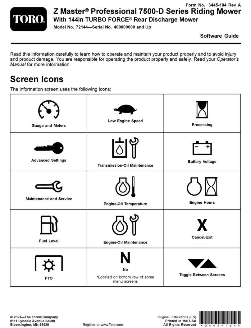
1. Remove the two bolts, washers, and locknuts that are on
the front of the machine and farthest to the outside
(Fig. 3).
2
2. Attach the light bracket to the front of the mower with
the bolts, washers, and nuts removed in step 1 (Fig. 3).
m–6654
13
7
4
3
7
6
5
4
2
Figure 3
1. Light assembly
2. Mower
3. Light connector
4. Bolt
5. Locknut
6. Washer
7. Wire harness
Installing the Switch
1. Remove the plug in the control panel.
2. Install the light switch into the control panel (Fig. 4).
m–6651
2
1
Figure 4
1. Control panel 2. Light switch
Installing the Wire Harness
1. Route the wire harness under the foot rest and above the
support rods (Fig. 5).
2. Connect the two head light connectors to the wire
harness (Fig. 3).
3. Install the wire harness clip into the hole in the front of
the machine (Fig. 5)
m–6652
4
2
11
3
5
6
Figure 5
1. Wire harness
2. Support rods
3. Mower
4. Footrest
5. Harness clip
6. Hole drilled in front
4. Route the harness along the right side of the footrest
and under the height–of–cut lever (Fig. 6).
5. Install the wire harness clips into the holes in the side of
the frame (Figures 6 and 7).
3
m–6655
3 1
2
4
12
Figure 6
1. Wire harness
2. Harness clip 3. Height–of–cut lever
4. Right side of footrest
m–6656
2 1 22
3
Figure 7
1. Wire harness
2. Harness clip 3. Right side of footrest
6. Line up the light wire harness connector with the light
switch (Fig. 8).
Important Make sure the round post on switch lines up
with hole in harness connector (Fig. 8).
Important Make sure the extended tab lines up with
the square hole in the switch (Fig. 8).
7. Install the light switch connector to the light switch
(Fig. 8).
8. Install the power terminal from the main harness into
the light power connector in the light harness (Fig. 8).
m–6653
6
4
5
3
2 3
7
8
2
9
1
Figure 8
1. Wire harness
2. Light switch
3. Light switch connector
4. Round post
5. Extended tab
6. Square hole in switch
7. Power terminal
8. Light power connector
9. Light wire harness
4
Installing the Fuse
1. Install the 10 amp fuse into the empty slot next to the
25 amp fuse in fuse block, as shown in Figure 9.
m–6648
23
1
Figure 9
1. Install 10 amp fuse here
2. 25 amp fuse 3. 30 amp fuse