Toro REELMASTER 6000 Series User manual

OPERATOR'S
MANUAL
FORM NO. 3321-714 Rev A
MODEL 03857—80001 AND UP
MODEL 03858—80001 AND UP
MODEL 03859—80001 AND UP
5, 7 & 11 BLADE REELS
®
REELMASTER 6000 SERIES
© The Toro Company 1998

REEL CONSTRUCTION: Fairway reels. All welded. 5,
7 or 11 blades
HEIGHT OF CUT RANGE:
5 Blade: 19 mm to 38 mm
7 Blade: 12.7 mm to 28 mm
11 Blade:9.5 mm to 19 mm
Note: Use bedknife Part No. 93-9774 for heights of cut
below 12.7 mm.
REEL DIAMETER: 17.7 mm
POWER: Reel motors feature quick disconnect for
removal or installation onto the cutting unit. Cutting
units can be driven from either end.
HEIGHT-OF-CUT & ROLLER ADJUSTMENT: Height-
of-cut adjustment is made at the rear roller with the
quick locating pin and/or threaded micro-adjustment.
The front roller position is adjustable, for setting unit
attitude.
BEDKNIFE AND BEDBAR ADJUSTMENT: Single-
point adjustment mechanism.
CLIP FREQUENCY: .9.5 mm—31.7mm. Reel speed
automatically adjusts to maintain proper clip. Reel
speed is continuously calculated based on the current
forward speed, reel type (number of blades) and height
of cut.
ROLLERS:
Front rollers: 7.62 cm diameter Wiehle rollers. Optional
7.62 cm diameter full rollers, Part No. 93-3040, are
available for the front position.
Rear rollers: 6.35 cm diameter full rollers. All rollers
use the same heavy-duty ball bearings with two
conventional single lip seals and a Toro labyrinth seal to
provide four sealing surfaces to protect the bearings.
ROLLER SCRAPER KITS:
Front Roller Scraper Part No. 95-7729
Rear Roller Scraper Kit Part No. 98-7996 (1 per kit)
2
Specifications

IMPORTANT: Read this Operator’s Manual
thoroughly before operating the cutting unit. Failure
to do so may result in damage to the cutting unit or
an unsatisfactory quality of cut.
IMPORTANT: Toro strongly recommends the use of a
leveling plate when setting up or adjusting any reel-
type cutting unit. The leveling plate will help to
ensure accurate and consistent adjustments.
Note: Right and left ends of the cutting unit are
determined by standing in the operator’s position
(Fig. 1).
Figure 1
After the cutting unit is unboxed, use the following
procedures to assure the cutting units are adjusted
properly.
1. Check each end of the reel for grease. Grease
should be visibly evident in the reel bearings and
internal splines of the reel shaft.
2. Insure that all nuts and bolts are securely fastened.
3. Make sure the carrier frame suspension operates
freely and does not bind when moved back and
forth.
4. Adjust the bedknife to the reel.
5. Adjust and level the front and rear rollers.
6. Set height of cut.
ADJUSTINGTHE BEDKNIFETO
THE REEL (Fig. 2–4)
1. A19-mm wrench will be needed to rotate the
bedknife adjustment knob. Each notch on the knob
will move the bedknife .013 mm (Fig.2).
Figure 2
1. Bedknife adjusting knob
2. Tip the cutting unit rearward to gain access to the
reel and bedknife (Fig. 3)
Figure 3
3. On either end of the reel, insert a long strip of dry
newspaper between the reel and bedknife. While
slowly rotating the reel into the bedknife, turn the
bedknife-adjusting knob clockwise, one click at a
time, until the paper is pinched lightly, which
results in a slight drag when the paper is pulled.
4. Check for light contact at the other end of the reel
using paper. If light contact is not evident or if a
gap exists, the bedknife is not parallel to reel.
Proceed to steps 5–9.
5. Slightly loosen (2) locknuts securing the pivot hub
to the left side plate (Fig. 4).
6. Rotate the pivot hub adjusting screw until a slightly
3
Adjusting the Cutting Unit

larger gap between the reel blades and the bed
knife exists on the left end than exists on the right
end (Fig. 4).
7. On the right end of the reel, insert a long strip of
dry newspaper between reel and bedknife. While
slowly rotating the reel toward the bedknife, turn
the bedknife adjusting knob clockwise, one click at
a time, until the paper is pinched lightly, which
results in a slight drag when the paper is pulled
Figure 4
1. Pivot hub
2. Pivot hub locknuts
3. Pivot hub adjusting screw
8. Rotate the pivot hub adjusting screw until the gap
between reel blades and bedknife is equal on both
ends.
9. Tighten the locknuts securing pivot hub to the left
side plate and verify adjustment.
ADJUSTING CUTTING UNIT
ATTITUDE
Adjustable front and rear brackets allow infinite
adjustment of cuffing unit “attitude”. Attitude refers to
the angle of the knife relative to the ground. Attitude
has a significant impact on the performance of the
cutting unit. All cutting units on a given machine must
be set to the same attitude.
In general, less aggressive attitudes are more
appropriate for lower heights of cut while, higher
heights of cut may require more aggressive attitudes.
An angle that is too flat will allow the bedbar or other
parts of the reel to drag in the turf causing tufting or
marks. Minimum recommended angle is 2 degrees.
The “best” cutting unit attitude is dependent on turf
conditions and desired results. Cutting unit attitude may
need to be adjusted throughout the cutting season to
allow for various turf conditions. Experience with the
cutting unit on the turf will determine the best_setting to
use. Wear of the bedknife and reel will result in changes
to cutting unit attitude, which must be compensated for
during setup and adjusted throughout the life of the
cutting unit.
The charts below give approximate dimensions for
setting up a new cutting unit to 6 degrees. Changes can
be made from this setting based on observed results in
the turf.
CUTTING UNIT SET-UP GUIDE
Note: If final height-of-cut settings other than those
shown in chart are desired, select the set of position
holes closest to desired height of cut. Use the top
capscrews to adjust to the final setting. Note: Set the
initial rear height of cut approximately 9.5 mm lower
for ease of adjustment.
4

5
Desired Height
of Cut
Rear Support Hole Rear Cutting Unit Side Plate Hole ••Rear Thread
Distance “R”
••Front Roller
Thread
Distance “F”
Upper Lower 1 2 3 4 5 6
*9.5 mm X X 13.5 mm 13.9 mm
*12.7 mm X X 14.2 mm 9.1 mm
15.9 mm X X 17.5 mm 6.1 mm
19.0 mm X X 13.7 mm 2.8 mm
22.2 mm X X 17.0 mm 0.0 mm
25.4 mm X X 13.2 mm –3.6 mm
28.6 mm X X 16.5 mm –6.6 mm
31.8 mm X X 12.9 mm –9.7 mm
34.9 mm X X 16.0 mm –12.9 mm
38.1 mm X X 12.5 mm –16.3 mm
*Optional low-cut bedknife (Part No. 93-9774) is required for height of cut below 12.7 mm).
**Rear thread distance is 4.8 mm shorter for initial set-up.
Rear Bracket Distance = R
Figure 5
1. Height-of -cut adjusting capscrew
2. Height-of-cut support
3. Quick height-of-cut pin
4. Roller bracket
Quick Height-Of-Cut Pin Holes
Figure 6
1. Side plate
2. Height-of -cut support
3. Upper hole
4. Lower hole
Front Bracket Distance = F
Figure 7

PRELIMINARY HEIGHT-OF-CUT
AND FRONT ROLLER SETTING
When setting up a cutting unit, or if repositioning or
installing a front or rear roller to the cutting unit,
proceed as follows:
1. Verify reel-to-bedknife contact before setting
height of cut.
2. Select the initial front roller bracket setting and rear
roller position holes for desired height of cut (Fig.
5, 6 & CHART).
3. Position the cutting unit on a flat level surface
(leveling plate).
4. Position an 11.3mm or thicker bar under the reel
blades and against the cutting edge of the bedknife.
Make sure the bar covers the full length of the reel
blades. The rear roller should not contact the
surface (Fig. 8).
CONTACT ALONG FULL LENGTH AT “A’ AND “B”
LEVELS THE FRONT ROLLER TO THE REEL
Figure 8
1. Rear roller
2. Front roller
3. Reel
4. “B”
5. Flat surface
6. Bedknife
7. Bar stock
5. Rock the cutting unit forward (on the reel blades
and steel bar) until the front roller contacts the flat
surface. The reel blades and bedknife must
maintain contact with the bar.
6. Adjust the front brackets until both ends of the
roller are in contact with the level surface. Use a
piece of paper or visually check to see if any gap
exists between the roller ends and the flat surface.
7. Tighten the top and bottom nuts of the front roller
brackets to 75–88 Nm.
8. Re-check roller contact with paper to insure the
roller has not changed position and is parallel with
the reel.
FINAL HEIGHT-OF-CUT SETTING
1. Using a gauge bar, Toro part no. 98-1852 or
equivalent (Fig. 9), set the head of the screw to the
desired height of cut. This measurement is from the
bar face to the underside of the screw head.
Figure 9
1. Final Height-Of-Cut Setting
2. Front Roller
3. Gauge Bar Assembly 98-1852
2. Place the gauge bar across the front and rear
rollers. Verify at each end (Fig. 10). Adjust as
required.
IMPORTANT: When set properly, front and rear
rollers will contact the gauge bar and the screw head
will be snug over the bedknife cutting edge at both
ends of the reel.
If an adjustment for desired height of cut or attitude is
required, either the front or rear roller may be adjusted.
Re-check leveling with a piece of paper and a leveling
plate after adjustments are complete.
6
12
3
4
567
1
2
3

Figure 10
1. Gauge bar
IMPORTANT: Each reel must be set consistently.
Minor differences in either height of cut or attitude
between cutting units may result in inconsistent
quality of cut.
ADJUSTTHE GRASS SHIELD
AND FINS
Adjust grass shield and/or shield fin angle for desired
grass clipping dispersion. For best dispersion under
most conditions:
1. Position the cutting unit on a flat level surface.
2. To adjust fins, unhook and move the front
mounting tab to the straight-ahead or angled
position slot.
3. To change grass shield angle, loosen the capscrew
(Fig. 11) securing the shield to the left side plate,
move the shield to desired angle and tighten screw.
Figure 11
1. Shield fin
2. Grass shield
3. Capscrew
ADJUSTTHE REAR SHIELD
Under most conditions, best dispersion is attained when
the rear shield is closed (front discharge).
When conditions are heavy or wet, the rear shield may
be opened.
1. To open the rear shield, loosen the capscrews
securing the shield to each side plate, rotate the
shield to the open position and tighten the screws.
ADJUST LIFT CHAIN
The chain connecting the carrier frame to the cutting
unit controls the amount of fore-aft rotation available
and the amount of ground clearance in transport and
turn around. The chain has 13 links. The chain is factory
adjusted at the eleventh link, which will work well for
most fairways.
On rougher ground, the chain may be shortened to allow
for more ground clearance. To allow greater rotation for
areas with many contours, lengthen the chain.
Note: The position of the screw within the link will
affect the chain length.
7

ADJUSTING CUTTING UNIT
ATTITUDE
(2-SCREW GAUGE BAR)
The cutting unit attitude may be adjusted or verified
using a gauge bar, Toro part no. 98-1852, which has two
screws and three hole locations. The second screw is
used in the inner hole to set or verify cutting attitude.
Adjust as follows:
1. Set the front screw height to the final height-of-cut
setting (Fig. 12).
2. Set the rear screw, distance “B”, lower than the
front setting (Fig. 12).
.20” (5.3mm) 8
.15” (3.8mm) 6
.09” (2.3mm) 4
.04” (1.0mm) 2
Figure 12
1. Adjust for final height-of-cut setting
3. Place a gauge bar across front and rear rollers. The
front screw head should fit snugly over the edge of
the bedknife and the end of the rear screw should
contact the bottom of the bedknife (Fig. 13 & 14).
Front and rear rollers should contact the gauge bar.
Verify attitude at each end.
Figure 13
1. Bedknife
Figure 14
8
1
1

Note: When backlapping, the front units all operate
together, and the rear units operate together.
1. Position the machine on a level surface, lower the
cutting units, stop the engine, engage the parking
brake, and move the Enable/Disable switch to the
Disable position.
2. Unlock and raise the seat to expose the controls.
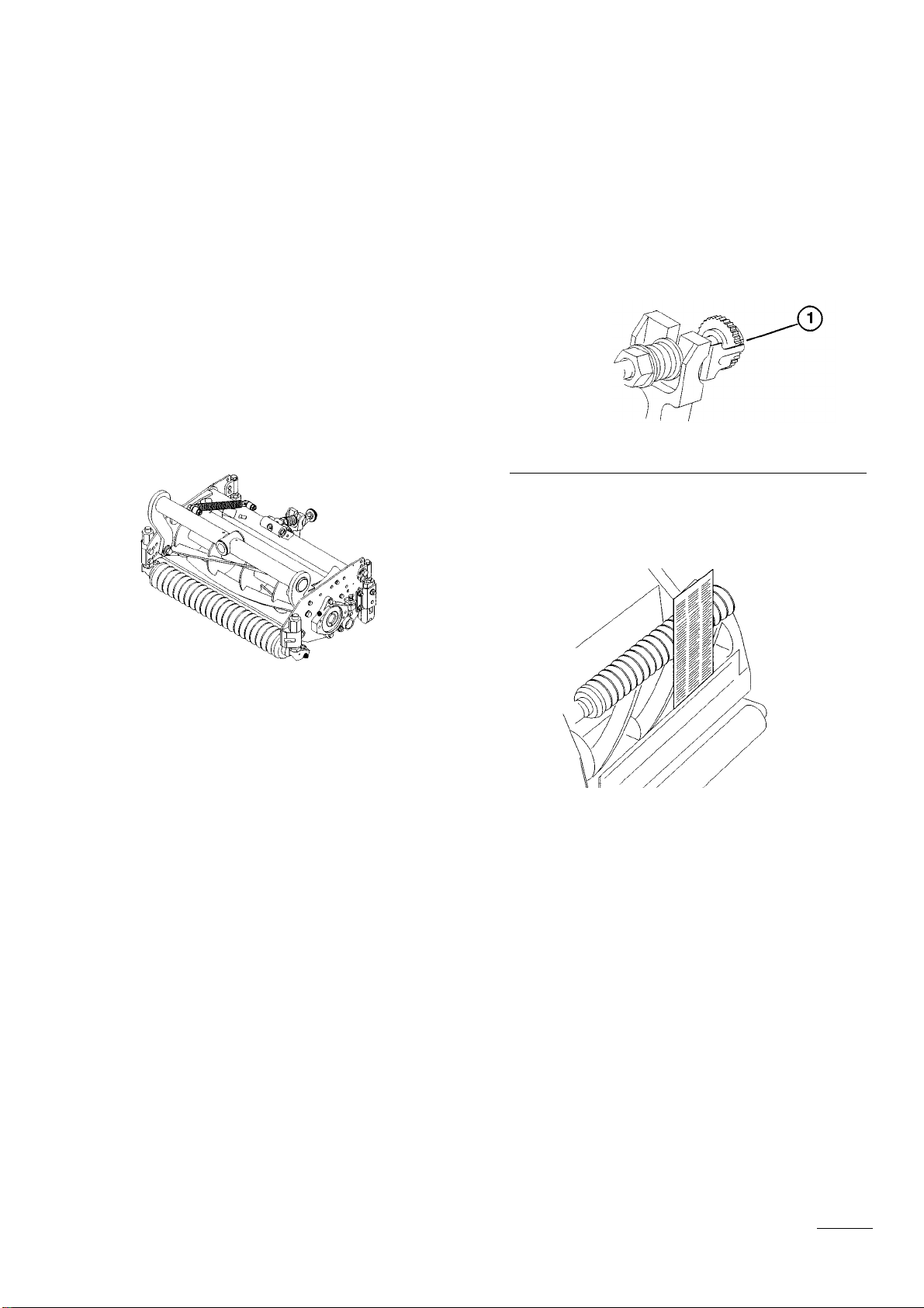
3. Open the control cover and turn the height-of-cut
selection knob to position “P”.
Note: Backlapping speed may be increased by
moving the height-of-cut selection knob toward to
‘A”. Each position will increase speed
approximately 60 rpm. After changing the selector,
wait 30 seconds for the system to respond to the
new speed target.
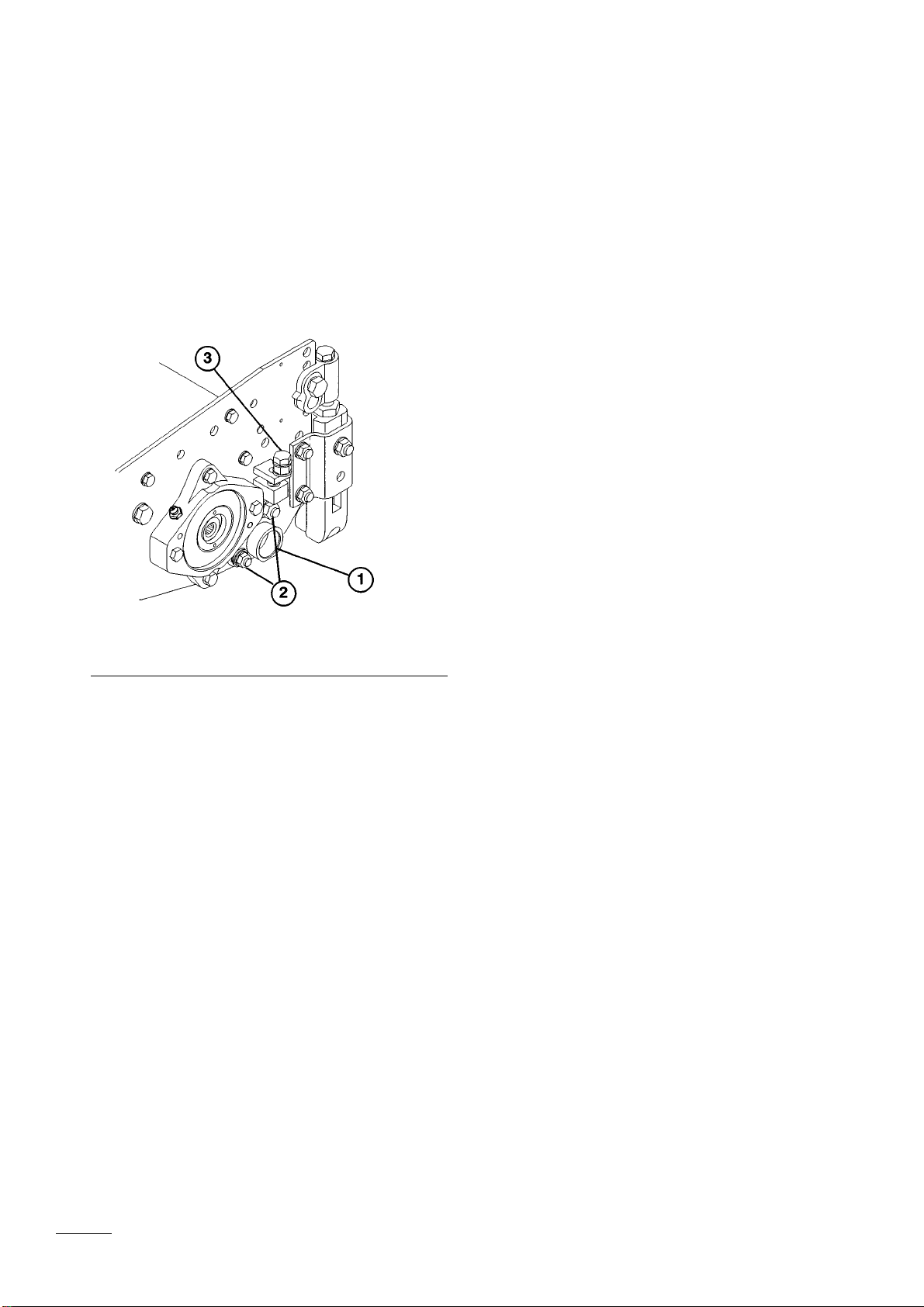
4. Make initial reel-to-bedknife adjustments for
backlapping on all cutting units that are to be
backlapped.
5. Start the engine and run it at idle speed.
6. Select either front or rear on the backlap switch to
determine whether front or rear reels will be
backlapped.
7. Move the Enable/Disable switch to the Enable
position. Move the Lower Mow/Lift control
forward to start backlapping operation on
designated reels.
8. Apply lapping compound with a long handle brush
(Toro Part No. 29-9100). Never use a short handled
brush.
9. If reels stall or become erratic while backlapping,
the reel control light will begin to blink and the
reels will turn off. If this occurs, turn the height-
of-cut selection knob one position closer to “A’.
Then toggle the Enable/Disable switch to the
Disable position followed by the Enable position.
To resume backlapping, move the Lower Mow/Lift
control lever forward.
10. To make an adjustment to the cutting units while
backlapping, turn reels OFF by moving the Lower
Mow/Raise lever rearward; move the
Enable/Disable switch to Disable and turn the
engine OFF. After adjustments have been
completed, repeat steps 5–9.
11. Repeat the procedure for all cutting units to be
backlapped.
12. When backlap operation has been completed,
return the backlap switch to OFF, lower the seat
and wash all lapping compound off the cutting
units. Adjust cutting unit as needed.
IMPORTANT: If the backlap switch is not returned to
the OFF position after backlapping, the cutting units
will not raise or function properly.
9
Reels may stall while backlapping. do not attempt to
restart the reels by hand, or touch the reels while
backlapping. Stop the engine and turn the height-of-
cut knob one position toward “A”.
DANGER
To avoid personal injury, never place hands
or feet in the reel area while the engine is
running. Changing engine speed while
backlapping may cause reels to stall. Never
change engine speed while backlapping. Only
backlap at idle engine speed. Never attempt to
turn reels by hand or foot while the engine is
running.
DANGER
To avoid personal injury, be certain that you
are clear of the cutting units before
proceeding.
DANGER
Backlapping Cutting Units

GREASING BEARINGS, BUSHINGS AND
PIVOT POINTS
Each cutting unit has (6) grease fittings (Fig. 15) that
must be lubricated regularly with No. 2 General Purpose
Lithium Base Grease.
Figure 15
The grease fitting locations shown in Figure 15 are for
each side of the cutting unit.
IMPORTANT: Lubricating cutting units immediately
after washing helps purge water out of bearings and
increases bearing life.
1. Wipe each grease fitting with a clean cloth.
2. Apply grease until pressure is felt against the
handle.
Note: Apply grease to reel bearing cavities until a
small amount is evident at the inboard reel seal.
3. Wipe excess grease away.
10
Lubrication


This manual suits for next models
3
Table of contents
Other Toro Lawn Mower Accessories manuals

Toro
Toro 30509 User manual

Toro
Toro Reelmaster 5510 User manual

Toro
Toro 126-8379 User manual

Toro
Toro 31204 User manual

Toro
Toro 44923 User manual

Toro
Toro 04480 User manual

Toro
Toro REELMASTER 5010 Series User manual

Toro
Toro 117-9449 User manual

Toro
Toro Super Recycler 115-8416 User manual

Toro
Toro 08838 User manual