Toro Greensmaster Flex 04853 User manual

FormNo.3457-379RevA
18inand21in,11-Bladeand
14-BladeEdgeSeries™Cutting
Unit
Greensmaster®Flex™1018TractionUnit
ModelNo.04853—SerialNo.410300000andUp
ModelNo.04854—SerialNo.410300000andUp
ModelNo.04863—SerialNo.410285710andUp
ModelNo.04864—SerialNo.410300000andUp
Registeratwww.Toro.com.
OriginalInstructions(EN)*3457-379*

ThisproductcomplieswithallrelevantEuropean
directives.Fordetails,pleaseseetheDeclarationof
Incorporation(DOI)atthebackofthispublication.
Introduction
Thiscuttingunitisintendedtobeusedbyprofessional,
hiredoperatorsincommercialapplications.Itis
primarilydesignedforcuttinggrassonwell-maintained
lawnsingolfcourses,parks,sportselds,andon
commercialgrounds.Usingthisproductforpurposes
otherthanitsintendedusecouldprovedangerousto
youandbystanders.
Readthisinformationcarefullytolearnhowtooperate
andmaintainyourproductproperlyandtoavoid
injuryandproductdamage.Youareresponsiblefor
operatingtheproductproperlyandsafely.
Visitwww.Toro.comforproductsafetyandoperation
trainingmaterials,accessoryinformation,helpnding
adealer,ortoregisteryourproduct.
Wheneveryouneedservice,genuineT oroparts,or
additionalinformation,contactanAuthorizedService
DealerorT oroCustomerServiceandhavethemodel
andserialnumbersofyourproductready.Figure1
identiesthelocationofthemodelandserialnumbers
ontheproduct.Writethenumbersinthespace
provided.
g308510
Figure1
1.Modelandserialnumberlocation
ModelNo.
SerialNo.
Thismanualidentiespotentialhazardsandhas
safetymessagesidentiedbythesafety-alertsymbol
(Figure2),whichsignalsahazardthatmaycause
seriousinjuryordeathifyoudonotfollowthe
recommendedprecautions.
g000502
Figure2
Safety-alertsymbol
Thismanualuses2wordstohighlightinformation.
Importantcallsattentiontospecialmechanical
informationandNoteemphasizesgeneralinformation
worthyofspecialattention.
Contents
Safety.......................................................................3
GeneralSafety...................................................3
CuttingUnitSafety..............................................3
BladeSafety.......................................................3
SafetyandInstructionalDecals..........................3
Setup........................................................................4
1InstallingtheRoller..........................................4
2InstallingtheCuttingUnittotheTraction
Unit.................................................................4
3AdjustingtheCuttingUnit.................................4
ProductOverview.....................................................5
Specications....................................................5
Attachments/Accessories...................................5
Operation..................................................................5
Maintenance.............................................................6
AccessingtheCuttingUnit..................................6
CheckingtheReel-DriveshaftGrease
Point................................................................6
AdjustingtheBedknife-to-ReelContact..............7
SettingtheCuttingUnittoMatchTurf
Conditions.......................................................8
PerformingtheHeight-of-CutAdjustment...........9
AdjustingtheClipRate......................................11
AdjustingtheCut-OffBar..................................12
ServicingtheBedbar........................................13
ServicingtheBedknife......................................14
BacklappingtheCuttingUnit.............................16
©2022—TheToro®Company
8111LyndaleAvenueSouth
Bloomington,MN554202
Contactusatwww.Toro.com.
PrintedintheUSA
AllRightsReserved

Safety
Thismachinehasbeendesignedinaccordancewith
ENISO5395andANSIB71.4-2017.
GeneralSafety
Thisproductiscapableofamputatinghandsandfeet.
Alwaysfollowallsafetyinstructionstoavoidserious
personalinjury.
•Readandunderstandthecontentsofthis
Operator’sManualbeforestartingthemachine.
•Useyourfullattentionwhileoperatingthe
machine.Donotengageinanyactivitythat
causesdistractions;otherwise,injuryorproperty
damagemayoccur.
•Donotputyourhandsorfeetnearmoving
componentsofthemachine.
•Donotoperatethemachinewithoutallguards
andothersafetyprotectivedevicesinplaceand
functioningproperlyonthemachine.
•Keepclearofanydischargeopening.
•Keepbystandersandchildrenoutoftheoperating
area.Neverallowchildrentooperatethemachine.
•Beforeyouleavetheoperator’sposition,dothe
following:
–Parkthemachineonalevelsurface.
–Lowerthecuttingunit(s).
–Disengagethedrives.
–Engagetheparkingbrake(ifequipped).
–Shutofftheengineandremovethekey.
–Waitforallmovementtostop.
Improperlyusingormaintainingthismachinecan
resultininjury.T oreducethepotentialforinjury,
complywiththesesafetyinstructionsandalways
payattentiontothesafety-alertsymbol,which
meansCaution,Warning,orDanger—personalsafety
instruction.Failuretocomplywiththeseinstructions
mayresultinpersonalinjuryordeath.
CuttingUnitSafety
•Thecuttingunitisonlyacompletemachinewhen
installedonatractionunit.Readthetraction
unitOperator’sManualcarefullyforcomplete
instructionsonthesafeuseofthemachine.
•Stopthemachine,removethekey(ifequipped),
andwaitforallmovementtostopbeforeinspecting
theattachmentafterstrikinganobjectorifthere
isanabnormalvibrationinthemachine.Makeall
necessaryrepairsbeforeresumingoperation.
•Keepallpartsingoodworkingconditionandall
hardwaretightened.Replaceallwornordamaged
decals.
•Useonlyaccessories,attachments,and
replacementpartsapprovedbyToro.
BladeSafety
Awornordamagedbladecanbreak,andapieceof
thebladecouldbethrowntowardyouorbystanders,
resultinginseriouspersonalinjuryordeath.
•Inspectthebladeperiodicallyforwearordamage.
•Usecarewhencheckingtheblades.Wrapthe
bladesorweargloves,andusecautionwhen
servicingtheblades.Onlyreplaceorsharpenthe
blades;neverstraightenorweldthem.
•Onmulti-bladedmachines,takecareasrotating1
bladecancauseotherbladestorotate.
SafetyandInstructionalDecals
Safetydecalsandinstructionsareeasilyvisibletotheoperatorandarelocatednearanyarea
ofpotentialdanger.Replaceanydecalthatisdamagedormissing.
decal120-9570
120-9570
1.Warning—stayawayfrommovingparts,keepallguards
andshieldsinplace.decal137-9706
137-9706
1.Cuttinghazardofthehandorfoot—shutofftheengine,
removethekeyordisconnectthesparkplug,waitforall
movingpartstostop,andreadtheOperator’sManual
beforeperformingmaintenance.
3

Setup
1
InstallingtheRoller
NoPartsRequired
Procedure
Thecuttingunitisshippedwithoutafrontroller.
ObtainarollerfromyourauthorizedT orodealerand
installitonthecuttingunit,asfollows:
1.Removetheplowbolt,washer,andangenut
securingoneoftheheight-of-cutarmstothe
cuttingunitsideplate(Figure3).
g310842
Figure3
1.Roller4.Adjustingscrew
2.Plowbolt5.Flangenut
3.Height-of-cutarm6.Roller-mountingscrew
2.Loosentheroller-mountingscrewsinthe
height-of-cutarms.
3.Slidetherollershaftintotheheight-of-cutarm
ontheoppositeendofthecuttingunit.
4.Slidetheheight-of-cutarmontotherollershaft.
5.Looselysecuretherollertothecuttingunitwith
theheight-of-cutarmandfastenerspreviously
removed.
6.Centertherollerbetweentheheight-of-cutarms.
7.Tightentheroller-mountingscrews.
8.Adjusttothedesiredheight-of-cutandtighten
theheight-of-cutarmmountingfasteners.
2
InstallingtheCuttingUnit
totheTractionUnit
NoPartsRequired
Procedure
Installthecuttingunittothetractionunit;referto
yourtractionunitOperator’sManualforinstallation
instructions.
3
AdjustingtheCuttingUnit
NoPartsRequired
Procedure
1.Accessthecuttingunit;refertoAccessingthe
CuttingUnit(page6).
2.Adjustthebedknifetothereel;refertoAdjusting
theBedknifeafterGrinding,Backlapping,or
Disassembly(page8).
3.Adjusttheheightofcut;refertoPerformingthe
Height-of-CutAdjustment(page9).
4

ProductOverview
Specications
Traction-unitcompatibilityThesecuttingunitsmountontheappropriately-sizedGreensmasterFlexoreFlex1018or
1021tractionunits.
ModelNo.04853and04854ModelNo.04863,04864
Cuttingwidth46cm(18inches)53cm(21inches)
Height-of-cutAdjustthefrontrollerheldby2verticalscrewsandnuts.
Height-of-cutrange
Thestandardbenchheight-of-cutrangeis1.6mm(0.062inch)to12.7mm(0.500inch).
Thebenchheight-of-cutrangewiththeHighHeightofCutKitinstalledis7mm(0.285inch)
to25mm(1.00inch).TheeffectiveHOCmayvarydependingonturfconditions,typeof
bedknife,rollers,andattachmentsinstalled.
ReelbearingsThereare2sealedstainlesssteel,deep-grooveballbearings.
FrontrollerThefrontrolleris6.3cm(2.5inches)indiameterwithavarietyofcongurationsselectedby
thecustomer.
Bedknife
ThismachinecomesstandardwithanEdgeMaxMicrocutbedknife.Optionalbedknives
withavarietyofcongurationsareavailable.Thebedknifeisfastenedtoamachined,
cast-ironbedbarwith13screws.
BedknifeadjustmentThereisadual-screwadjustmenttothereelwithdetentscorrespondingto0.018mm
(0.0007inch)bedknifemovementforeachindexedposition.
GrassshieldTheshieldenhancesgrassdischargefromthereelinwetconditions.
CounterweightAcast-ironweightmountedoppositetothedrivelinebalancesthecuttingunit.
ModelNo.04853ModelNo.04854ModelNo.04863ModelNo.04864
Netweight34kg(74lb)35kg(77lb)35kg(77lb)36kg(80lb)
CliprateRefertoyourtractionunitOperator’sManual.
Attachments/Accessories
AselectionofToroapprovedattachmentsandaccessoriesisavailableforusewiththemachinetoenhance
andexpanditscapabilities.ContactyourAuthorizedServiceDealerorauthorizedTorodistributororgoto
www.T oro.comforalistofallapprovedattachmentsandaccessories.
Toensureoptimumperformanceandcontinuedsafetycerticationofthemachine,useonlygenuineT oro
replacementpartsandaccessories.Replacementpartsandaccessoriesmadebyothermanufacturerscouldbe
dangerous,andsuchusecouldvoidtheproductwarranty.
Operation
RefertoyourtractionunitOperator’sManualfordetailedoperationinstructions.Beforeusingthecuttingunit
eachday,adjustthebedknife;refertoAdjustingtheBedknifeDaily(page7).T estthequalityofcutbycuttinga
testswathbeforeusingthecuttingunitonagreentoensurethatthenishedcutiscorrect.
5

Maintenance
AccessingtheCuttingUnit
Accessthebedknifeandreelformaintenanceas
follows:
•Withthecuttingunitremovedfromthemachine,
propuptherearofthecuttingunittoensurethat
thenutsonthebackendofthebedbaradjusting
screwsarenotrestingontheworksurface(Figure
4).
g311262
Figure4
1.Prop(notprovided)2.Bedknifeadjustingscrew
nut(2)
•Withthecuttingunitattachedtothemachine,lower
thetraction-unithandletotheground(Figure5).
g310731
Figure5
Checkingthe
Reel-DriveshaftGrease
Point
ServiceInterval:Yearly
1.Removethehardwarethatsecuresthereel-drive
assemblytothesideplate(Figure6).
g310788
Figure6
1.Socket-headscrew2.Nut
2.Removethenutsfromtheinsideoftheside
plate(Figure6).
3.Checktheinsideofthereeldriveshaft(Figure7)
foranyremaininggrease.
Ifyoudonotseeasufcientamountofgrease,
addmoregreasetothemaleandfemalespline
shaft.
g310809
Figure7
1.Reeldriveshaft
4.Usethepreviouslyremovedsocket-headscrews
andnutstosecurethereel-driveassemblyto
thesideplate.
5.Installthecuttingunittothetractionunit;referto
yourtractionunitOperator’sManual.
6

Adjustingthe
Bedknife-to-ReelContact
AdjustingtheBedknifeDaily
Priortomowingeachday,orasrequired,verifyproper
bedknife-to-reelcontact.Performthisprocedure
eventhoughqualityofcutisacceptable.
Note:Thisprocedurecanbeperformedwiththe
cuttingunitinstalledtothetractionunit.
1.Shutoffthetractionunit.
2.Accessthecuttingunit;refertoAccessingthe
CuttingUnit(page6).
3.Slowlyrotatethereelinareversedirection,
listeningforreel-to-bedknifecontact.
•Ifnocontactisevident,adjustthebedknife
asfollows
A.Turnthebedbaradjustingscrews
clockwise(Figure8),1clickatatime,
untilyoufeelandhearlightcontact.
Note:Thebedbaradjustingscrews
havedetentscorrespondingto0.018
mm(0.0007inch)bedknifemovement
foreachindexedposition.
g014595
Figure8
1.Bedbaradjustingscrew
B.Insertalongstripofcuttingperformance
paper(ToroPartNo.125-5610)between
thereelandbedknife,perpendicularto
thebedknife(Figure9),thenslowly
rotatethereelforward;itshouldcutthe
paper;ifnot,repeatstepsAandBuntil
itdoes.
•Ifexcessivecontact/reeldragisevident,
backlap,refacethefrontofthebedknife,or
grindthecuttingunittoachievethesharp
edgesneededforprecisioncutting(Referto
theToroManualforSharpeningReeland
RotaryMowers,FormNo.09168SL).
Important:Lightcontactispreferredatall
times.Ifyoudonotmaintainlightcontact,
thebedknife/reeledgeswillnotsufciently
self-sharpen,anddullcuttingedgeswill
resultafteraperiodofoperation.Ifyou
maintainexcessivecontact,bedknife/reel
wearwillbeaccelerated,unevenwearcan
result,andthequalityofcutmaydecline.
Note:ForeFlexcuttingunits,the
reel-to-bedknifecontacthasasignicant
impactonenergyconsumption.Verylight
contactisbestforcuttingperformanceand
batteryconsumption.
Note:Asthereelbladescontinuetorunagainst
thebedknife,aslightburrwillappearonthefront
cuttingedgesurfacealongthefulllengthofthe
bedknife.Occasionallyrunaleacrossthefront
edgetoremovethisburrtoimprovecutting.
Afterextendedrunning,aridgewilleventually
developatbothendsofthebedknife.Round
offthesenotchesorlethemushwiththe
cuttingedgeofthebedknifetoensuresmooth
operation.
7

AdjustingtheBedknifeafter
Grinding,Backlapping,or
Disassembly
Usethisprocedureduringinitialcutting-unitsetupand
aftergrinding,backlapping,ordisassemblingthereel.
Thisisnotadailyadjustment.
Note:Thisprocedurecanbeperformedwiththe
cuttingunitinstalledtothetractionunit.
Note:ForeFlexcuttingunits,thereel-to-bedknife
contacthasasignicantimpactonenergy
consumption.Verylightcontactisbestforcutting
performanceandbatteryconsumption.
1.Shutoffthetractionunit.
2.Accessthecuttingunit;refertoAccessingthe
CuttingUnit(page6).
3.Rotatethereelsothat1ofthebladescrosses
thebedknifeedgebetweentherstandsecond
bedknifescrewheadslocatedontherightside
ofthecuttingunit.
4.Makeanidentifyingmarkonthebladewhereit
crossesthebedknifeedge.
Note:Thiswillmakelateradjustmentseasier.
5.Inserta0.05mm(0.002inch)shim(T oroPart
No.140-5531)betweenthebladeandthe
bedknifeedgeatthepointmarkedinstep4.
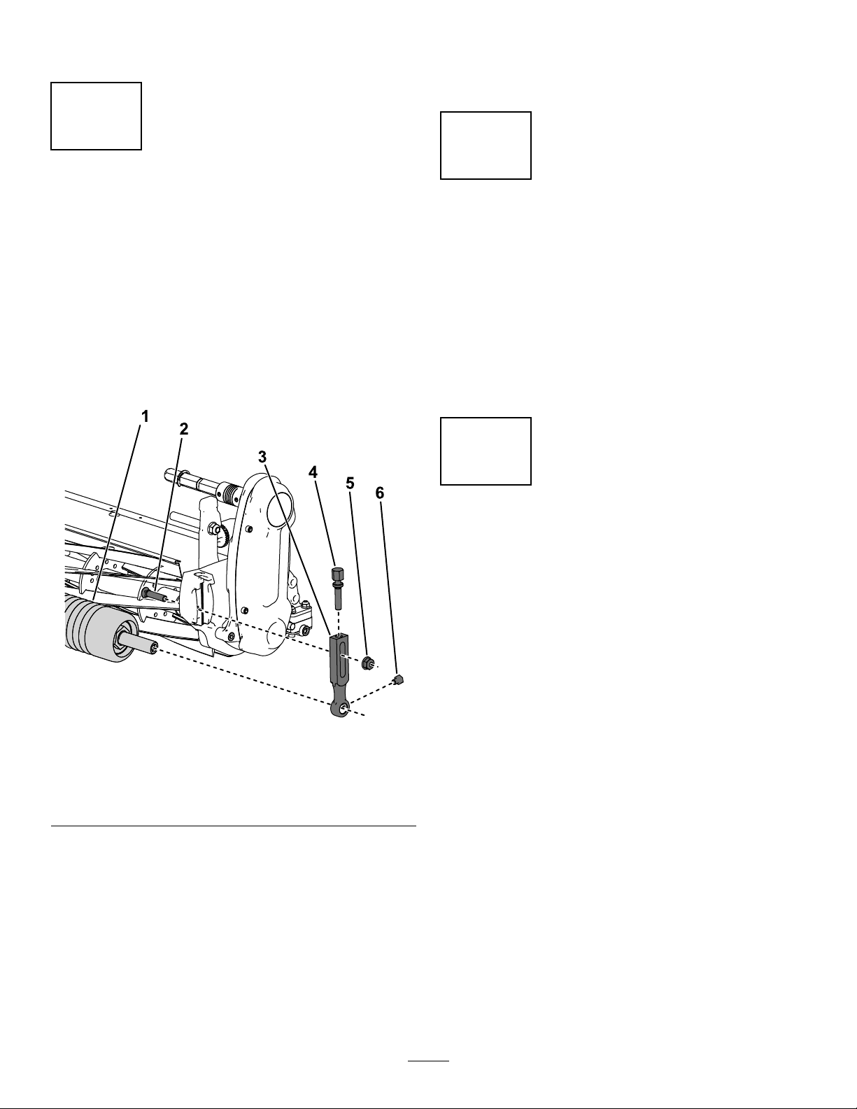
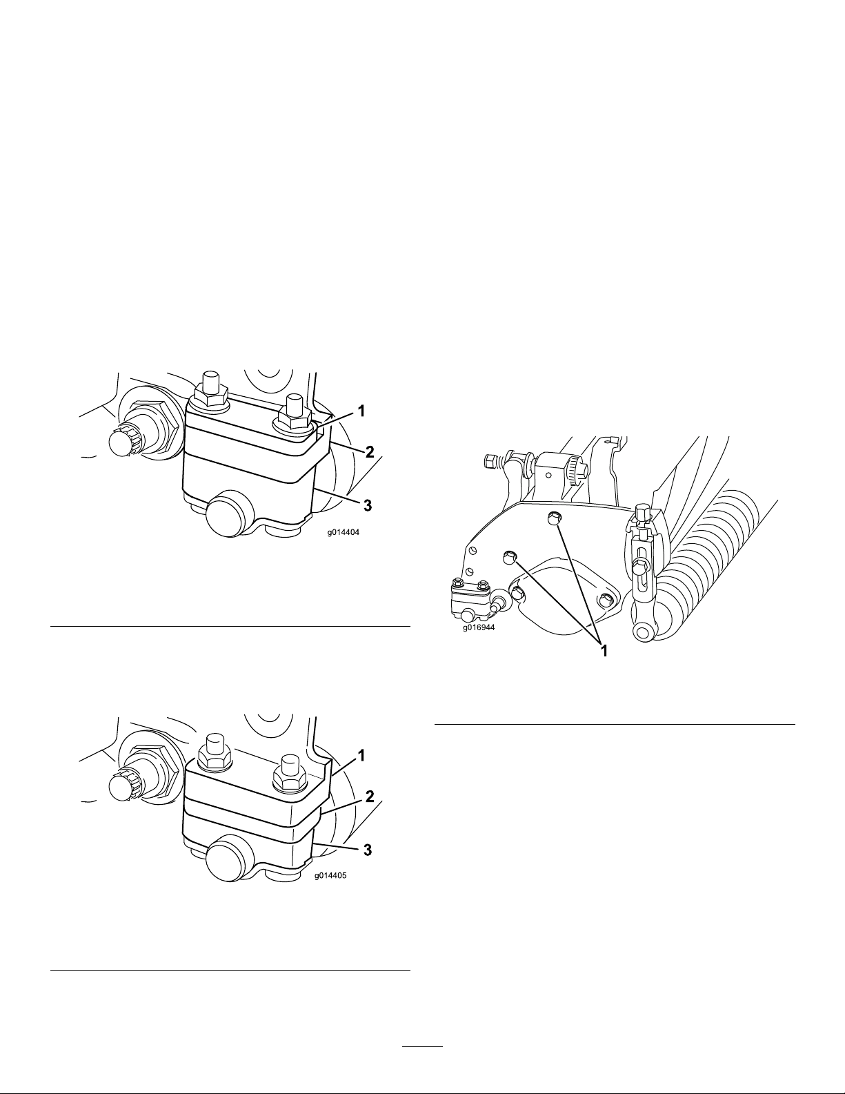
6.Turntherightbedbaradjustingscrew(Figure8)
untilyoufeellightpressureontheshimwhen
slidingitside-to-side.Removetheshim.
7.Fortheleftsideofthecuttingunit,slowlyrotate
thereelsothattheclosestbladecrossesthe
bedknifeedgebetweentherstandsecond
screwheads.
8.Repeatsteps4through6fortheleftsideofthe
cuttingunitandleftbedbaradjustingscrew.
9.Repeatsteps5and6untilthereislightpressure
atthecontactpointsonboththeleftandright
sidesofthecuttingunit.
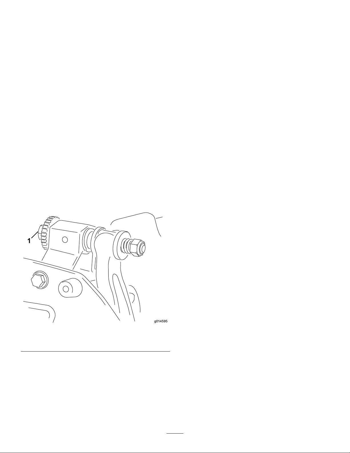
10.Toobtainlightcontactbetweenthereeland
bedknife,turneachbedbaradjustingscrew
clockwise3clicks.
Note:Eachclickonthebedbaradjustingscrew
movesthebedknife0.018mm(0.0007inches).
Donotovertightentheadjustingscrews.
Turningtheadjustingscrewclockwisemoves
thebedknifeedgeclosertothereel.Turningthe
adjustingscrewcounterclockwisemovesthe
bedknifeedgeawayfromthereel.
11.Insertalongstripofcuttingperformancepaper
(ToroPartNo.125-5610)betweenthereeland
bedknife,perpendiculartothebedknife(Figure
9),thenslowlyrotatethereelforward;itshould
cutthepaper;ifnot,turneachbedbaradjusting
screwclockwise1clicksandrepeatthisstep
untilitcutsthepaper.
g310820
Figure9
Note:Ifexcessivecontactorreeldragisevident,
youmaybacklap,refacethefrontofthebedknife,
orgrindthecuttingunittoachievethesharpedges
neededforprecisioncutting(RefertotheToroManual
forSharpeningReelandRotaryMowers,FormNo.
09168SL).
SettingtheCuttingUnitto
MatchTurfConditions
Usethefollowingtabletodeterminetheproper
bedknifethatisneededtomatchyourturfconditions.
ContactyourauthorizedTorodistributortoacquire
additionalbedknivesandrollers.
RefertoAdjustingtheClipRate(page11)for
instructionstosettheappropriatecliprateforyour
turfconditions.
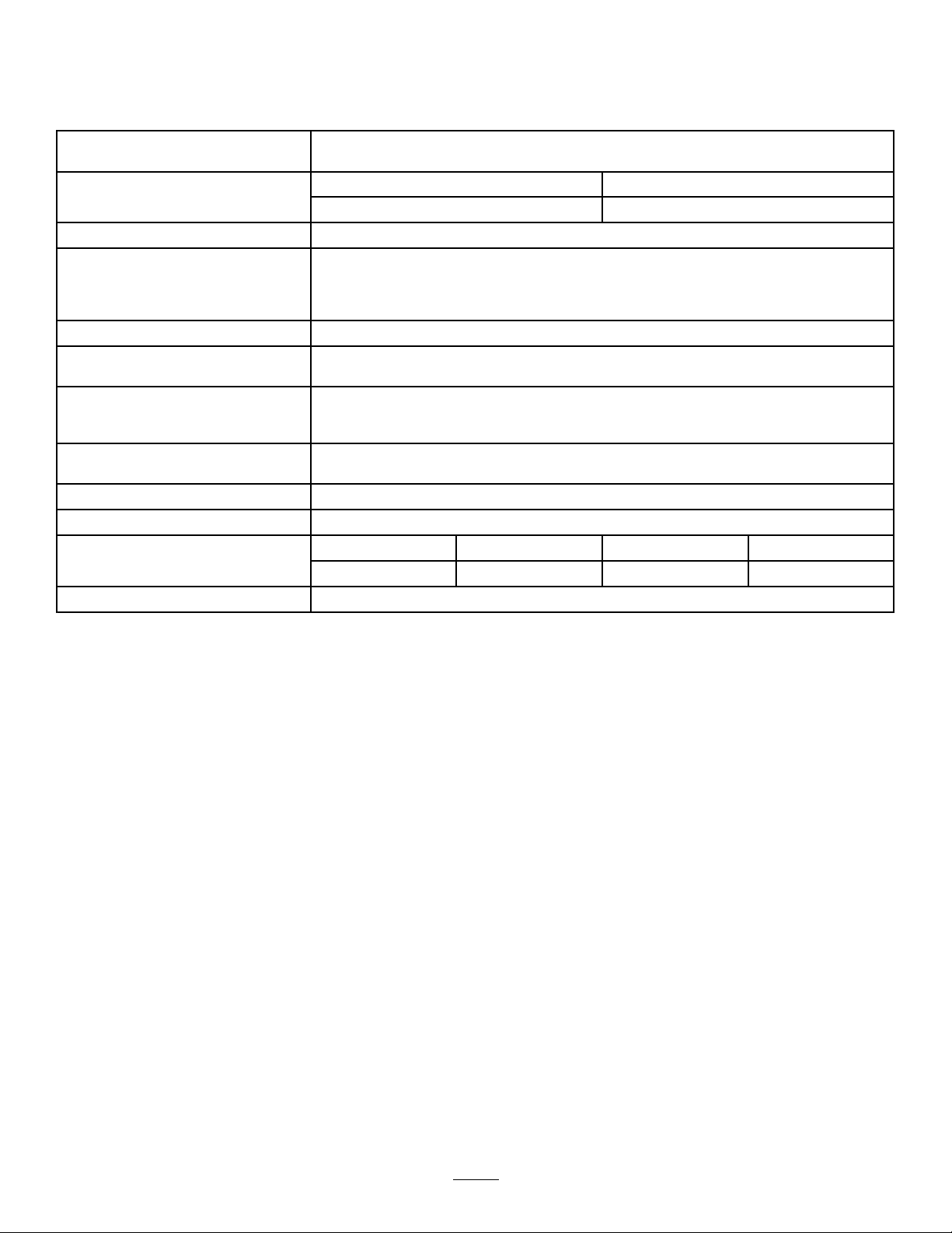
RecommendedBedknife/HeightofCutChart
BedknifeHeightofCut
EdgemaxMicro-cut
(Standard)
1.5to4.7mm(0.062–0.188inch)
EdgemaxT ournament
(Optional)
3.1to12.7mm(0.125–0.500inch)
Micro-cut(Optional)1.5to4.7mm(0.062–0.188inch)
Tournament(Optional)3.1to12.7mm(0.125–0.500inch)
ExtendedMicro-cut
(Optional)
1.5to4.7mm(0.062–0.188inch)
ExtendedT ournament
(Optional)
3.1to12.7mm(0.125–0.500inch)
Low-cut(Optional)4.7to25.4mm(0.188–1.00inch)
8

Performingthe
Height-of-CutAdjustment
Settheheightofcuttothedesiredheightusinga
height-of-cutgauge,andensurethatyourcuttingunit
isequippedwithabedknifethatisbestsuitedforyour
desiredheightofcut;refertoSettingtheCuttingUnit
toMatchTurfConditions(page8).
AdjustingtheRearRollerHeight
Dependingonyourdesiredheight-of-cutrange,adjust
therearrollerbrackets(Figure10orFigure11)tothe
loworhighposition:
•Positionthespacerabovethesideplate-mounting
ange(factorysetting)whentheheight-of-cut
settingsrangefrom1.5mmto6mm(1/16inchto
1/4inch)asshowninFigure10.
g014404
Figure10
1.Spacer3.Rollerbracket
2.Sideplate-mountingange
•Positionthespacerbelowthesideplate-mounting
angewhentheheight-of-cutsettingsrangefrom
3mmto25mm(1/8inchto1inch)asshown
inFigure11.
g014405
Figure11
1.Sideplate-mountingange3.Rollerbracket
2.Spacer
1.Raisetherearofthecuttingunitandplacea
blockunderthebedknife.
2.Removethe2nutssecuringeachrollerbracket
andspacertoeachsideplatemountingange.
3.Lowertherollerandscrewsfromthesideplate
mountingangesandspacers.
4.Placethespacersontothescrewsaboveof
belowtherollerbrackets,asrequired(Figure
10orFigure11).
5.Securetherollerbracketandspacerstothe
undersideofthemountingangeswiththenuts
previouslyremoved.
6.Verifythatthebedknife-to-reelcontactiscorrect.
Tipthemowertoexposethefrontandrear
rollersandthebedknife.
Note:Thepositionoftherearrollertothereel
iscontrolledbythemachiningtolerancesof
theassembledcomponentsandparallelingis
notrequired.Alimitedamountofadjustmentis
possiblebysettingthecuttingunitonasurface
plateandlooseningthesideplatemountingbolts
(Figure12).Adjustandtightentheboltswhen
nished.
g016944
Figure12
1.Sideplate-mountingbolts
Important:Wheneveryoumusttipthe
cuttingunittoexposethebedknife/reel,prop
uptherearofthecuttingunittoensure
thatthenutsonthebackendofthebedbar
adjustingscrewsarenotrestingonthework
surface(Figure4).
AdjustingtheHeight-of-CutGauge
Beforeadjustingtheheightofcut,settheheight-of-cut
gaugeasfollows:
1.Loosenthenutonthegaugebarandsetthe
adjustingscrewtothedesiredheightofcut
(Figure13).
9

Note:Thedistancebetweenthebottomofthe
screwheadandthefaceofbaristheheightof
cut.
g000489
Figure13
1.Gaugebar3.Nut
2.Height-adjustingscrew
2.Tightenthenut.
AdjustingtheHeightofCut
ThiscuttingunitcomesstandardwiththeEdgemax
Micro-cutbedknifeandstandardbedbar.The
effectiveheightofcutdependsonpreviousmower
congurationsandturfconditions(i.e.,rollertype,
bedknifebehindcenterdistance,softorrmgreens,
seasonconditions).Settheinitialheightofcut0.25
mmto0.38mm(0.010to0.015inch)higherthanthe
previousgreensmowersetupandadjustittomatch
conditions.
Note:Forheightsofcutgreaterthan13mm(0.500
inch),installthehigh-height-of-cutkit.
RefertoSettingtheCuttingUnittoMatchTurf
Conditions(page8)todeterminewhichbedknifeis
bestsuitedforthedesiredheightofcut.
1.Loosenthelocknutssecuringtheheight-of-cut
armstothecutting-unitsideplates(Figure14).
g310831
Figure14
1.Adjustingscrew3.Height-of-cutarm
2.Flangelocknut
2.Hookthescrewheadoftheheight-of-cutgauge
barontotherightsideofthecuttingedgeofthe
bedknifeandresttherearendofthebaronto
therearroller(Figure15).
10

g016945
Figure15
1.Gaugebar
3.Rotatetheadjustingscrewuntiltheroller
contactsthefrontofthegaugebar.
4.Repeatsteps2andfortheleftside.
5.Adjustbothendsoftherolleruntiltheentire
rollerisparalleltothebedknife.
Important:Whensetproperly,therearand
frontrollerscontactthegaugebarandthe
screwissnugagainstthebedknife.This
ensuresthattheheightofcutisidenticalat
bothendsofthebedknife.
6.Tightenthelocknutsontheheight-of-cutarms
tosecuretheadjustmentenoughtoremoveplay
fromthewasher.
7.Verifythattheheight-of-cutsettingiscorrect;
repeatthisprocedureifnecessary
AdjustingtheClipRate
Thecliprateisdeterminedbythefollowingmachine
settings:
•Reelspeed:Thereelspeedcanbeadjustedto
ahighorlowsetting;refertoyourtractionunit
Operator’sManual.
•Reel-drive-pulleyposition:Thereel-drivepulleys
(22-toothand24-tooth)canbesetin2positions:
–HIGHposition:“A”inFigure16
–LOWposition:“B”inFigure16
Note:ThepulleypositionissettotheLOW
positionfromthefactory.
g310843
Figure16
1.Pulley(24tooth)2.Pulley(22tooth)
Toadjustthepositionofthepulleys,refertothe
followingsteps:
1.Removethebeltcovertoexposethebelt(Figure
17).
11

g310844
Figure17
1.Reel-drive-assembly
housing
5.Idler-armbolt
2.Belt6.Beltcover
3.Idler-arminternalhex7.Socket-headscrew
4.Idlerarm
2.Loosentheidler-armboltandrotatetheidler
arm(Figure17)toreleasetensiononthebelt.
3.Removethebelt(Figure17).
4.Loosenthenutoneachpulley,removethe
pulleys,andusethenutstoinstallthepulleysin
yourdesiredconguration.
g310845
Figure18
1.Nut3.Pulley(24tooth)
2.Pulley(22tooth)
5.Torquethepulleynutsto37to45N∙m(27to
33ft-lb)
6.Installthebeltandtensionthebeltbyapplying6
to7N∙m(55to60in-lb)totheidler-arminternal
hexshowninFigure17.
7.Tightentheidler-armboltandinstallthebelt
cover.
AdjustingtheCut-OffBar
Adjustthecut-offbartoensurethattheclippingsare
cleanlydischargedfromthereelarea,asfollows:
Note:Thebarisadjustabletocompensatefor
changesinturfconditions.Adjustthebarcloserto
thereelwhentheturfisextremelydry.Bycontrast,
adjustthebarfurtherawayfromthereelwhentheturf
conditionsarewet.Thebarshouldbeparalleltothe
reeltoensureoptimumperformance.Adjustitafter
sharpeningthereelonareelgrinder.
1.Loosenthescrewssecuringthetopbar(Figure
19)tothecuttingunit.
g014643
Figure19
1.Cut-offbar
2.Inserta1.5mm(0.060inch)feelergauge
betweenthetopofthereelandthebarand
tightenthescrews.
Important:Ensurethatthebarandreelare
equaldistanceapartacrossthecomplete
reel.
12

ServicingtheBedbar
Onlyaproperlytrainedmechanicshouldservicethe
bedbarandbedknifetopreventdamagetothereel,
bedbar,orbedknife.Ideally,takethecuttingunitto
yourauthorizedT orodistributorforservice.Referto
theServiceManualforyourtractionunitforcomplete
instructions,specialtools,anddiagramsforservicing
thebedknife.Shouldyoueverneedtoremove
orassemblethebedbaryourself,instructionsare
providedbelow,asarethespecicationsforservicing
thebedknife.
Important:Alwaysfollowthebedknife
proceduresdetailedinyourServiceManualwhen
servicingthebedknife.Failuretoinstallandgrind
thebedknifecorrectlycanleadtodamagetothe
reel,bedbar,orbedknife.
RemovingtheBedbar
1.Turnthebedbaradjusting-screw
counterclockwisetobackthebedknife
awayfromthereel(Figure20).
g014641
Figure20
1.Bedbar-adjustingscrew3.Bedbar
2.Spring-tensionnut4.Washer
2.Backoutthespring-tensionnutuntilthewasher
isnolongertensionedagainstthebedbar
(Figure20).
3.Oneachsideofthemachine,loosenthelocknut
showninFigure21.
g310846
Figure21
1.Bedbarbolt4.Plasticwasher
2.Nut5.Bedbar
3.Steelwasher
4.Removeeachbedbarbolt,allowingthebedbar
tobepulleddownwardandremovedfromthe
cuttingunit(Figure21).
Accountforthe2plasticwashersand1steel
washeroneachendofthebedbar(Figure21).
13

InstallingtheBedbar
1.Installthebedbar,positioningthemountingears
betweenthewashersandthebedbar-adjusting
screw(Figure20).
2.Securethebedbartoeachsideplatewiththe
bedbarbolts(nutsonbolts)and3washers(6
total).
3.Positionanylonwasheroneachsideofthe
side-plateboss.Placeasteelwasheroutside
eachofthenylonwashers(Figure22).
4.Torquethebedbarboltsto27to36N∙m(240to
320inch-lb).
5.Tightenthelocknutsuntilyouremovetheend
playfromsteelwashers,butyouareableto
rotatethembyhand.Thewashersontheinside
mayhaveagap.
Important:Donotovertightenthelocknuts
ortheywilldeectthesideplates.
6.Tightenthespringtensionnutuntilthespringis
collapsed,thenbackitoff1/2turn(Figure22).
g006505
Figure22
1.Spring-tensionnut2.Spring
7.Adjustthebedknifetothereel;refertoAdjusting
theBedknifeafterGrinding,Backlapping,or
Disassembly(page8).
ServicingtheBedknife
InstallingtheBedknife
1.Removetherust,scale,andcorrosionfromthe
bedbarsurfaceandapplyathinlayerofoilto
thebedbarsurface.
2.Cleanthescrewthreads.
3.Applyanti-seizecompoundtothescrewsand
installthebedknifetothebedbar.
g255045
Figure23
1.Bedbar3.Screw
2.Bedknife
4.Torquethe2outerscrewsto1N∙m(10in-lb).
5.Workingfromthecenterofthebedknife,torque
thescrewsto23to28N∙m(200to250in-lb).
14

g255046
Figure24
1.Bednifescrewtool3.T orqueto23to28N∙m
(200to250in-lb).
2.Installandtorquethese
rstto1N∙m(10in-lb).
6.Grindthebedknife.
PreparingtheReelforGrinding
1.Ensurethatallcuttingunitcomponentsarein
goodconditionandcorrectanyissuesbefore
grinding.
2.Followthereelgrindermanufacturer’s
instructionstogrindthecuttingreeltothe
followingspecications.
ReelGrindingSpecications
NewReelDiameter128.5mm(5.06inches)
ReelDiameterServiceLimit114.3mm(4.5inches)
BladeReliefAngle30°±5°
BladeLandWidth1.0mm(0.04inches)
BladeLandWidthRange0.76to1.27mm(0.03to0.05
inches)
ReelDiameterTaperService
Limit
0.25mm(0.01inch)
Relief-GrindingtheReel
Thenewreelhasalandwidthof0.76to1.27mm
(0.030to0.050inch)anda30°reliefgrind.
Whenthelandwidthgetslargerthan3mm(0.120
inch)wide,dothefollowing:
1.Applya30°reliefgrindonallreelbladesuntil
thelandwidthis1.3mm(0.050inch)wide
(Figure25).
g278332
Figure25
1.30°2.1.3mm(0.050inch)
2.Spingrindthereeltoachieve<0.025mm(0.001
inch)reelrun-out.
Note:Thiscausesthelandwidthtogrow
slightly.
3.Adjustthecuttingunit;refertoyourcuttingunit
Operator’sManual.
Note:T oextendthelongevityofthesharpnessofthe
edgeofthereelandthebedknife—aftergrindingthe
reeland/orthebedknife—checkthereeltobedknife
contactagainaftercutting2greens,asanyburrs
willberemoved.Burrsmaycreateimproperreelto
bedknifeclearance,whichcanacceleratewear.
15

BedknifeGrindingSpecications
g032182
Figure26
1.Reliefangle4.Frontface
2.T opface5.Frontangle
3.Removeburr
Standardbedknifereliefangle3°minimum
Extendedbedknifereliefangle7°minimum
FrontAngleRange13°to17°
CheckingtheTopGrindAngle
Theanglethatyouusetogrindyourbedknivesis
veryimportant.
Usetheangleindicator(T oroPartNo.131-6828)and
theangle-indicatormount(T oroPartNo.131-6829)to
checktheanglethatyourgrinderproducesandthen
correctforanygrinderinaccuracy.
1.Placetheangleindicatoronthebottomsideof
thebedknifeasshowninFigure27.
g034113
Figure27
1.Bedknife(vertical)2.Angleindicator
2.PresstheAltZerobuttonontheangleindicator.
3.Placetheangle-indicatormountontheedge
ofthebedknifesothattheedgeofthemagnet
mateswiththeedgeofthebedknife(Figure28).
Note:Thedigitaldisplayshouldbevisiblefrom
thesamesideduringthisstepasitwasinstep1.
g034114
Figure28
1.Angle-indicatormount3.Bedknife
2.Edgeofthemagnetmated
withtheedgeofthe
bedknife
4.Angleindicator
4.Placetheangleindicatoronthemountasshown
inFigure28.
Note:Thisistheanglethatyourgrinder
produces,andshouldbewithin2degreesofthe
recommendedtopgrindangle.
BacklappingtheCutting
Unit
Tobacklapthecuttingunit,usetheAccessBacklap
Kit(ModelNo.139-4342);refertotheoperating
instructionsinthekitInstallationInstructions.Contact
yourauthorizedT orodistributortoacquirethiskit.
16

DeclarationofIncorporation
TheT oroCompany,8111LyndaleAve.South,Bloomington,MN,USAdeclaresthatthefollowingunit(s)
conform(s)tothedirectiveslisted,wheninstalledinaccordancewiththeaccompanyinginstructionsontocertain
ToromodelsasindicatedontherelevantDeclarationsofConformity.
ModelNo.SerialNo.ProductDescriptionInvoiceDescriptionGeneralDescriptionDirective
04853410300000andUp
18in11-BladeEdgeSeries
CuttingUnit,Greensmaster
Flex1018Mower
11-BLADE18INFLEXESCULawnMower
2000/14/EC,
2005/88/EC,
2006/42/EC
04854410300000andUp
18in14-BladeEdgeSeries
CuttingUnit,Greensmaster
Flex1018Mower
14-BLADE18INFLEXESCULawnMower
2000/14/EC,
2005/88/EC,
2006/42/EC
04863410285710andUp
21in11-BladeEdgeSeries
CuttingUnit,Greensmaster
FlexoreFlex1021Mower
11-BLADE21INFLEXESCULawnMower
2000/14/EC,
2005/88/EC,
2006/42/EC
04864410300000andUp
21in14-BladeEdgeSeries
CuttingUnit,Greensmaster
FlexoreFlex1021Mower
14-BLADE21INFLEXESCULawnMower
2000/14/EC,
2005/88/EC,
2006/42/EC
RelevanttechnicaldocumentationhasbeencompiledasrequiredperPartBofAnnexVIIof2006/42/EC.
Wewillundertaketotransmit,inresponsetorequestsbynationalauthorities,relevantinformationonthispartly
completedmachinery.Themethodoftransmissionshallbeelectronictransmittal.
ThismachineryshallnotbeputintoserviceuntilincorporatedintoapprovedToromodelsasindicatedonthe
associatedDeclarationofConformityandinaccordancewithallinstructions,wherebyitcanbedeclaredin
conformitywithallrelevantDirectives.
Certied:AuthorizedRepresentative:
MarcelDutrieux
ManagerEuropeanProductIntegrity
ToroEuropeNV
Nijverheidsstraat5
2260Oevel
Belgium
TomLangworthy
EngineeringDirector
8111LyndaleAve.South
Bloomington,MN55420,USA
October24,2022

UKDeclarationofIncorporation
TheT oroCompany,8111LyndaleAve.South,Bloomington,MN,USAdeclaresthatthefollowingunit(s)
conform(s)totheregulationslisted,wheninstalledinaccordancewiththeaccompanyinginstructionsonto
certainToromodelsasindicatedontherelevantDeclarationsofConformity.
ModelNo.SerialNo.ProductDescriptionInvoiceDescriptionGeneralDescriptionRegulation
04853410300000andUp
18in11-BladeEdgeSeries
CuttingUnit,Greensmaster
Flex1018Mower
11-BLADE18INFLEXESCULawnMower
S.I.2001
No.1701,
S.I.2008No.
1597
04854410300000andUp
18in14-BladeEdgeSeries
CuttingUnit,Greensmaster
Flex1018Mower
14-BLADE18INFLEXESCULawnMower
S.I.2001
No.1701,
S.I.2008No.
1597
04863410285710andUp
21in11-BladeEdgeSeries
CuttingUnit,Greensmaster
FlexoreFlex1021Mower
11-BLADE21INFLEXESCULawnMower
S.I.2001
No.1701,
S.I.2008No.
1597
04864410300000andUp
21in14-BladeEdgeSeries
CuttingUnit,Greensmaster
FlexoreFlex1021Mower
14-BLADE21INFLEXESCULawnMower
S.I.2001
No.1701,
S.I.2008No.
1597
RelevanttechnicaldocumentationhasbeencompiledasrequiredperSchedule10ofS.I.2008No.1597.
Wewillundertaketotransmit,inresponsetorequestsbynationalauthorities,relevantinformationonthispartly
completedmachinery.Themethodoftransmissionshallbeelectronictransmittal.
ThismachineryshallnotbeputintoserviceuntilincorporatedintoapprovedToromodelsasindicatedonthe
associatedDeclarationofConformityandinaccordancewithallinstructions,wherebyitcanbedeclaredin
conformitywithallrelevantRegulations.
Thisdeclarationhasbeenissuedunderthesoleresponsibilityofthemanufacturer.
TheobjectofthedeclarationisinconformitywithrelevantUKlegislation.
AuthorizedRepresentative:
MarcelDutrieux
ManagerEuropeanProductIntegrity
ToroU.K.Limited
SpellbrookLaneWest
Bishop'sStortford
CM234BU
UnitedKingdom
TomLangworthy
EngineeringDirector
8111LyndaleAve.South
Bloomington,MN55420,USA
October24,2022

EEA/UKPrivacyNotice
Toro’sUseofYourPersonalInformation
TheToroCompany(“Toro”)respectsyourprivacy.Whenyoupurchaseourproducts,wemaycollectcertainpersonalinformationaboutyou,eitherdirectly
fromyouorthroughyourlocalT orocompanyordealer.Torousesthisinformationtofullcontractualobligations-suchastoregisteryourwarranty,
processyourwarrantyclaimortocontactyouintheeventofaproductrecall-andforlegitimatebusinesspurposes-suchastogaugecustomer
satisfaction,improveourproductsorprovideyouwithproductinformationwhichmaybeofinterest.Toromayshareyourinformationwithoursubsidiaries,
afliates,dealersorotherbusinesspartnersinconnectiontheseactivities.Wemayalsodisclosepersonalinformationwhenrequiredbylaworin
connectionwiththesale,purchaseormergerofabusiness.Wewillneversellyourpersonalinformationtoanyothercompanyformarketingpurposes.
RetentionofyourPersonalInformation
Torowillkeepyourpersonalinformationaslongasitisrelevantfortheabovepurposesandinaccordancewithlegalrequirements.Formoreinformation
aboutapplicableretentionperiodspleasecontact[email protected].
Toro’sCommitmenttoSecurity
YourpersonalinformationmaybeprocessedintheUSoranothercountrywhichmayhavelessstrictdataprotectionlawsthanyourcountryofresidence.
Wheneverwetransferyourinformationoutsideofyourcountryofresidence,wewilltakelegallyrequiredstepstoensurethatappropriatesafeguardsare
inplacetoprotectyourinformationandtomakesureitistreatedsecurely.
AccessandCorrection
Youmayhavetherighttocorrectorreviewyourpersonaldata,orobjecttoorrestricttheprocessingofyourdata.Todoso,pleasecontactusbyemail
at[email protected].IfyouhaveconcernsaboutthewayinwhichT orohashandledyourinformation,weencourageyoutoraisethisdirectlywithus.
PleasenotethatEuropeanresidentshavetherighttocomplaintoyourDataProtectionAuthority.
374-0282RevC

TheToroWarranty
Two-Yearor1,500HoursLimitedWarranty
ConditionsandProductsCovered
TheToroCompanywarrantsyourT oroCommercialproduct(“Product”)
tobefreefromdefectsinmaterialsorworkmanshipfor2yearsor
1,500operationalhours*,whicheveroccursrst.Thiswarrantyis
applicabletoallproductswiththeexceptionofAerators(referto
separatewarrantystatementsfortheseproducts).Whereawarrantable
conditionexists,wewillrepairtheProductatnocosttoyouincluding
diagnostics,labor,parts,andtransportation.Thiswarrantybegins
onthedatetheProductisdeliveredtotheoriginalretailpurchaser.
*Productequippedwithanhourmeter.
InstructionsforObtainingWarrantyService
YouareresponsiblefornotifyingtheCommercialProductsDistributoror
AuthorizedCommercialProductsDealerfromwhomyoupurchasedthe
Productassoonasyoubelieveawarrantableconditionexists.Ifyouneed
helplocatingaCommercialProductsDistributororAuthorizedDealer,or
ifyouhavequestionsregardingyourwarrantyrightsorresponsibilities,
youmaycontactusat:
ToroCommercialProductsServiceDepartment
8111LyndaleAvenueSouth
Bloomington,MN55420-1196
952–888–8801or800–952–2740
E-mail:[email protected]
OwnerResponsibilities
Astheproductowner,youareresponsibleforrequiredmaintenanceand
adjustmentsstatedinyourOperator'sManual.Repairsforproductissues
causedbyfailuretoperformrequiredmaintenanceandadjustmentsarenot
coveredunderthiswarranty.
ItemsandConditionsNotCovered
Notallproductfailuresormalfunctionsthatoccurduringthewarranty
periodaredefectsinmaterialsorworkmanship.Thiswarrantydoesnot
coverthefollowing:
•Productfailureswhichresultfromtheuseofnon-T ororeplacement
parts,orfrominstallationanduseofadd-on,ormodiednon-T oro
brandedaccessoriesandproducts.
•Productfailureswhichresultfromfailuretoperformrecommended
maintenanceand/oradjustments.
•ProductfailureswhichresultfromoperatingtheProductinanabusive,
negligent,orrecklessmanner.
•Partsconsumedthroughusethatarenotdefective.Examplesofparts
whichareconsumed,orusedup,duringnormalProductoperation
include,butarenotlimitedto,brakepadsandlinings,clutchlinings,
blades,reels,rollersandbearings(sealedorgreasable),bedknives,
sparkplugs,castorwheelsandbearings,tires,lters,belts,andcertain
sprayercomponentssuchasdiaphragms,nozzles,owmeters,and
checkvalves.
•Failurescausedbyoutsideinuence,including,butnotlimitedto,
weather,storagepractices,contamination,useofunapprovedfuels,
coolants,lubricants,additives,fertilizers,water,orchemicals.
•Failureorperformanceissuesduetotheuseoffuels(e.g.gasoline,
diesel,orbiodiesel)thatdonotconformtotheirrespectiveindustry
standards.
•Normalnoise,vibration,wearandtear,anddeterioration.Normal
“wearandtear”includes,butisnotlimitedto,damagetoseatsdueto
wearorabrasion,wornpaintedsurfaces,scratcheddecalsorwindows.
Parts
Partsscheduledforreplacementasrequiredmaintenancearewarranted
fortheperiodoftimeuptothescheduledreplacementtimeforthatpart.
Partsreplacedunderthiswarrantyarecoveredforthedurationofthe
originalproductwarrantyandbecomethepropertyofT oro.Torowillmake
thenaldecisionwhethertorepairanyexistingpartorassemblyorreplace
it.Toromayuseremanufacturedpartsforwarrantyrepairs.
DeepCycleandLithium-IonBatteryWarranty
DeepcycleandLithium-Ionbatterieshaveaspeciedtotalnumber
ofkilowatt-hourstheycandeliverduringtheirlifetime.Operating,
recharging,andmaintenancetechniquescanextendorreducetotal
batterylife.Asthebatteriesinthisproductareconsumed,theamount
ofusefulworkbetweenchargingintervalswillslowlydecreaseuntilthe
batteryiscompletelywornout.Replacementofwornoutbatteries,
duetonormalconsumption,istheresponsibilityoftheproductowner.
Note:(Lithium-Ionbatteryonly):Refertothebatterywarrantyforadditional
information.
LifetimeCrankshaftWarranty(ProStripe02657Model
Only)
TheProstripewhichisttedwithagenuineToroFrictionDiscand
Crank-SafeBladeBrakeClutch(integratedBladeBrakeClutch(BBC)+
FrictionDiscassembly)asoriginalequipmentandusedbytheoriginal
purchaserinaccordancewithrecommendedoperatingandmaintenance
procedures,arecoveredbyaLifetimeWarrantyagainstenginecrankshaft
bending.Machinesttedwithfrictionwashers,BladeBrakeClutch(BBC)
unitsandothersuchdevicesarenotcoveredbytheLifetimeCrankshaft
Warranty.
MaintenanceisatOwner’sExpense
Enginetune-up,lubrication,cleaningandpolishing,replacementoflters,
coolant,andcompletingrecommendedmaintenancearesomeofthe
normalservicesToroproductsrequirethatareattheowner’sexpense.
GeneralConditions
RepairbyanAuthorizedToroDistributororDealerisyoursoleremedy
underthiswarranty.
TheToroCompanyisnotliableforindirect,incidentalorconsequential
damagesinconnectionwiththeuseoftheToroProductscoveredby
thiswarranty,includinganycostorexpenseofprovidingsubstitute
equipmentorserviceduringreasonableperiodsofmalfunctionor
non-usependingcompletionofrepairsunderthiswarranty.Except
fortheEmissionswarrantyreferencedbelow,ifapplicable,thereisno
otherexpresswarranty.Allimpliedwarrantiesofmerchantabilityand
tnessforusearelimitedtothedurationofthisexpresswarranty.
Somestatesdonotallowexclusionsofincidentalorconsequential
damages,orlimitationsonhowlonganimpliedwarrantylasts,sotheabove
exclusionsandlimitationsmaynotapplytoyou.Thiswarrantygivesyou
speciclegalrights,andyoumayalsohaveotherrightswhichvaryfrom
statetostate.
NoteRegardingEmissionsWarranty
TheEmissionsControlSystemonyourProductmaybecoveredby
aseparatewarrantymeetingrequirementsestablishedbytheU.S.
EnvironmentalProtectionAgency(EPA)and/ortheCaliforniaAirResources
Board(CARB).Thehourlimitationssetforthabovedonotapplytothe
EmissionsControlSystemWarranty.RefertotheEngineEmissionControl
WarrantyStatementsuppliedwithyourproductorcontainedintheengine
manufacturer’sdocumentation.
CountriesOtherthantheUnitedStatesorCanada
CustomerswhohavepurchasedT oroproductsexportedfromtheUnitedStatesorCanadashouldcontacttheirToroDistributor(Dealer)toobtain
guaranteepoliciesforyourcountry,province,orstate.IfforanyreasonyouaredissatisedwithyourDistributor'sserviceorhavedifcultyobtaining
guaranteeinformation,contactyourAuthorizedT oroServiceCenter.
374-0253RevI
This manual suits for next models
3
Table of contents
Other Toro Lawn Mower Accessories manuals

Toro
Toro 08755 User manual

Toro
Toro Recycler Kit 131-4184 User manual

Toro
Toro Groundsmaster e3200 User manual

Toro
Toro TX 1000 User manual

Toro
Toro 30215 User manual

Toro
Toro 04260 User manual

Toro
Toro Universal Groomer Drive Kit User manual

Toro
Toro 88710 User manual

Toro
Toro 117-3600 User manual

Toro
Toro 120-3290 User manual