Toro 02710 User manual

FormNo.3450-372RevA
81cm(32in),91cm(36in),
or122cm(48in)Mid-Size
Rear-DischargeDeck
ModelNo.02710—SerialNo.410000000andUp
ModelNo.02711—SerialNo.410000000andUp
ModelNo.02712—SerialNo.410000000andUp
Registeratwww.Toro.com.
OriginalInstructions(EN)*3450-372*

ThisproductcomplieswithallrelevantEuropean
directives;fordetails,pleaseseetheseparateproduct
specicDeclarationofConformity(DOC)sheet.
Introduction
Thisrotary-bladelawncuttingdeckismounted
toaride-onmachineandisintendedtobeused
byprofessional,hiredoperatorsincommercial
applications.Itisprimarilydesignedforcuttinggrass
onwell-maintainedlawnsinparks,sportselds,and
oncommercialgrounds.
Readthisinformationcarefullytolearnhowtooperate
andmaintainyourproductproperlyandtoavoid
injuryandproductdamage.Youareresponsiblefor
operatingtheproductproperlyandsafely.
Visitwww.T oro.comforproductsafetyandoperation
trainingmaterials,accessoryinformation,helpnding
adealer,ortoregisteryourproduct.
Wheneveryouneedservice,genuineT oroparts,or
additionalinformation,contactanAuthorizedService
DealerorT oroCustomerServiceandhavethemodel
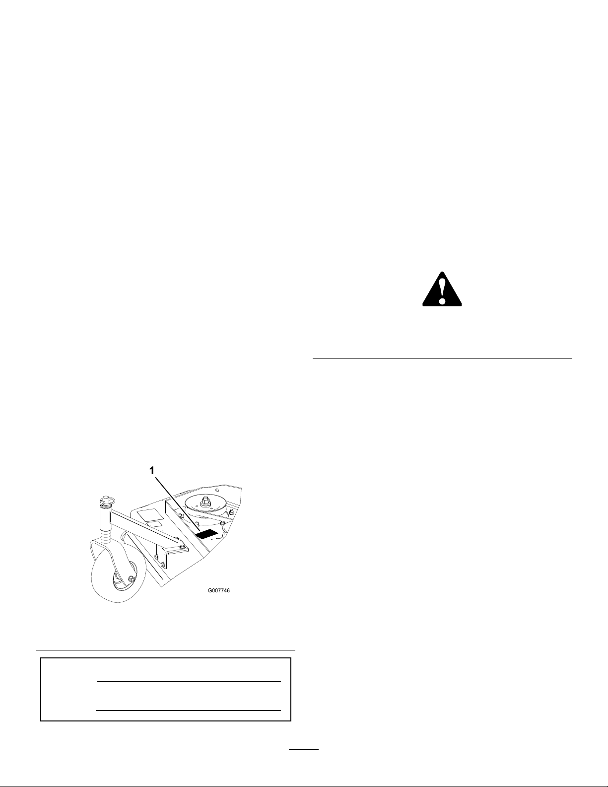
andserialnumbersofyourproductready.Figure1
identiesthelocationofthemodelandserialnumbers
ontheproduct.Writethenumbersinthespace
provided.
Important:Withyourmobiledevice,youcan
scantheQRcodeontheserialnumberdecal(if
equipped)toaccesswarranty,parts,andother
productinformation.
g007746
Figure1
1.Modelandserialnumberlocation
ModelNo.
SerialNo.
Thismanualuses2wordstohighlightinformation.
Importantcallsattentiontospecialmechanical
informationandNoteemphasizesgeneralinformation
worthyofspecialattention.
Thesafety-alertsymbol(Figure2)appearsbothin
thismanualandonthemachinetoidentifyimportant
safetymessagesthatyoumustfollowtoavoid
accidents.Thissymbolwillappearwiththeword
Danger,Warning,orCaution.
•Dangerindicatesanimminentlyhazardous
situationwhich,ifnotavoided,willresultindeath
orseriousinjury.
•Warningindicatesapotentiallyhazardous
situationwhich,ifnotavoided,couldresultin
deathorseriousinjury.
•Cautionindicatesapotentiallyhazardoussituation
which,ifnotavoided,mayresultinminoror
moderateinjury.
sa-black
Figure2
Safety-alertsymbol
Contents
Safety.......................................................................3
GeneralSafety...................................................3
CuttingUnitSafety..............................................3
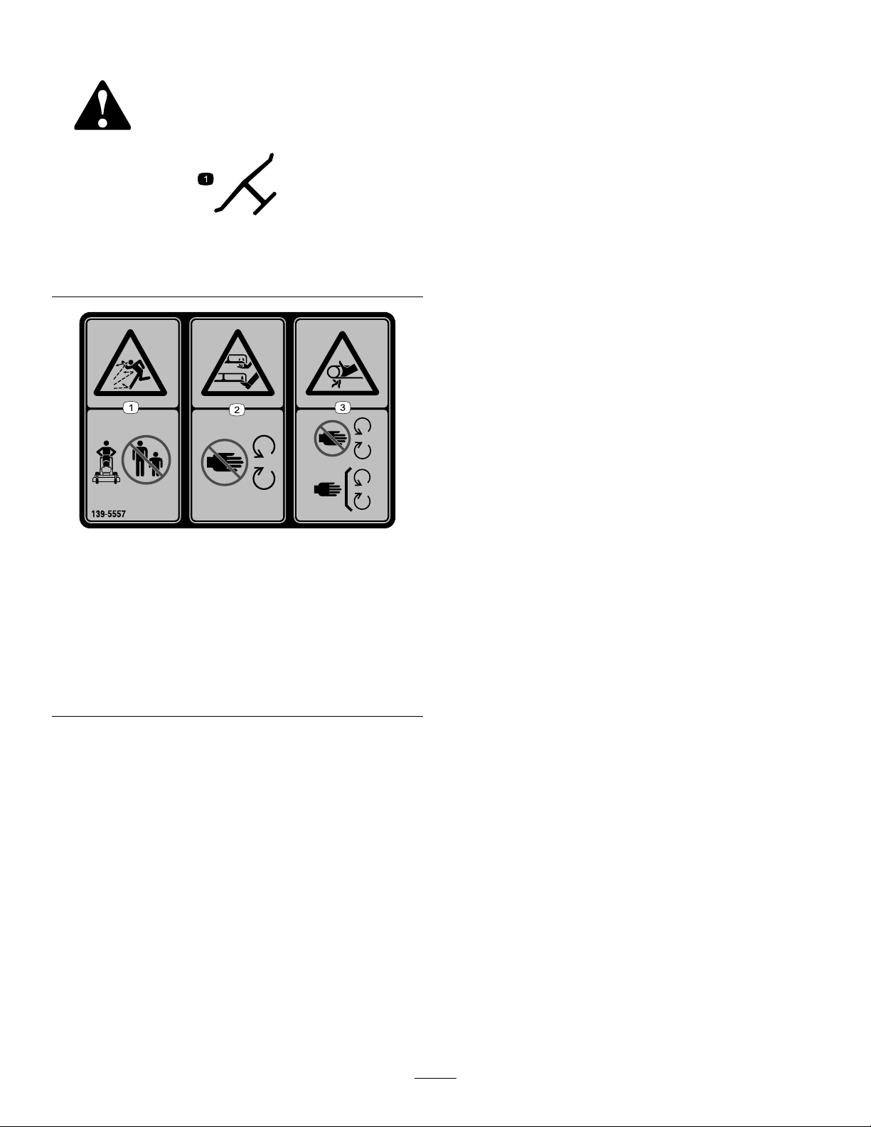
SafetyandInstructionalDecals..........................4
ProductOverview.....................................................5
Specications....................................................5
Attachments/Accessories...................................5
Operation..................................................................6
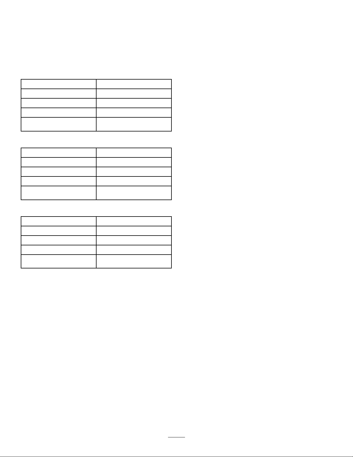
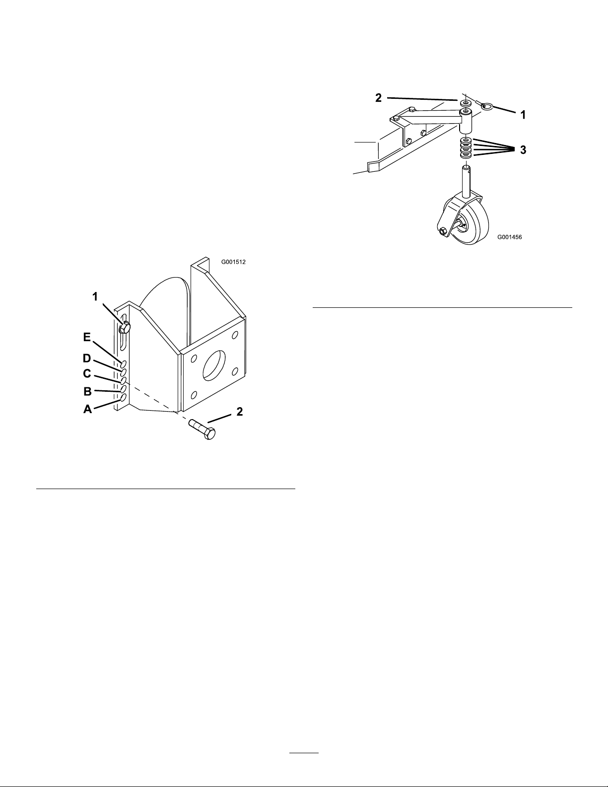
AdjustingtheHeightofCut.................................6
Height-of-CutChart............................................8
Maintenance.............................................................9
RecommendedMaintenanceSchedule(s).............9
Lubrication..........................................................10
LubricatingtheCasterandWheel
Bearings........................................................10
GreasingtheMower-BeltIdler..........................10
GreasingtheMowerDeck................................10
BeltMaintenance.................................................11
CheckingtheBelts.............................................11
ReplacingtheMowerBelt..................................11
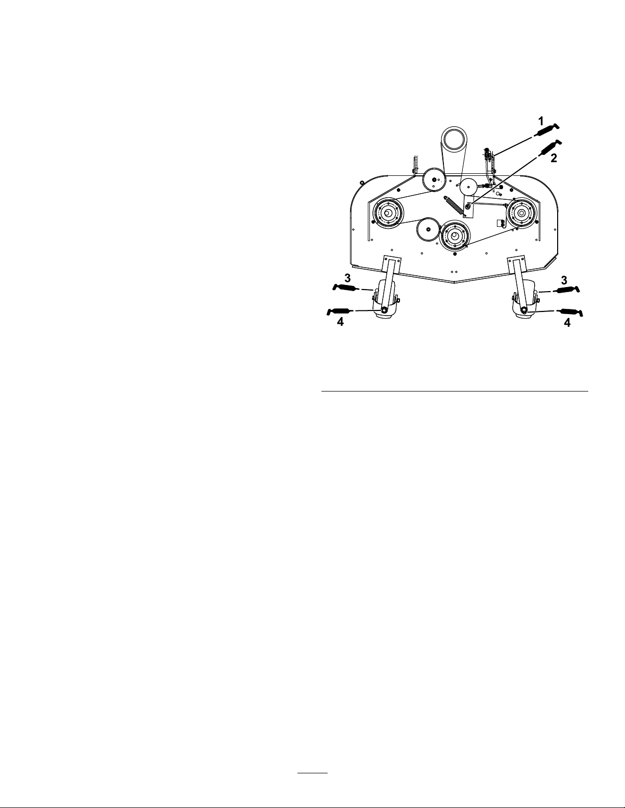
AdjustingtheMowerBeltTension......................11
MowerDeckMaintenance....................................14
BladeSafety.....................................................14
ServicingtheCuttingBlades.............................14
AdjustingtheBladeBrake.................................16
Storage...................................................................16
©2021—TheToro®Company
8111LyndaleAvenueSouth
Bloomington,MN554202
Contactusatwww.Toro.com.
PrintedintheUSA
AllRightsReserved

Safety
Thismachinehasbeendesignedinaccordancewith
ENISO5395.
GeneralSafety
Thisproductiscapableofamputatinghandsand
feetandofthrowingobjects.Alwaysfollowallsafety
instructionstoavoidseriouspersonalinjury.
•Read,understand,andfollowtheinstructions
andwarningsinthisOperator’sManualandon
themachineandattachmentsbeforestartingthe
engine.
•Donotputyourhandsorfeetnearmovingpartsof
orunderthemachine.Keepclearofanydischarge
opening.
•Donotoperatethemachinewithoutallguards
andothersafetyprotectivedevicesinplaceand
functioningproperlyonthemachine.
•Keepbystandersandchildrenoutoftheoperating
area.Donotallowchildrentooperatethemachine.
Allowonlypeoplewhoareresponsible,trained,
familiarwiththeinstructions,andphysically
capabletooperatethemachine.
•Stopthemachine,shutofftheengine,remove
theignitionkey(ifequipped),andwaitforall
movingpartstostopbeforeservicing,fueling,or
uncloggingthemachine.
Improperlyusingormaintainingthismachinecan
resultininjury.Toreducethepotentialforinjury,
complywiththesesafetyinstructionsandalways
payattentiontothesafety-alertsymbol,which
meansCaution,Warning,orDanger—personalsafety
instruction.Failuretocomplywiththeseinstructions
mayresultinpersonalinjuryordeath.
CuttingUnitSafety
•Thecuttingunitisonlyacompletemachinewhen
installedonatractionunit.Readthetraction
unitOperator’sManualcarefullyforcomplete
instructionsonthesafeuseofthemachine.
•Stopthemachine,removethekey,andwaitfor
allmovingpartstostopbeforeinspectingthe
attachmentafterstrikinganobjectorifthereis
anabnormalvibrationinthemachine.Makeall
necessaryrepairsbeforeresumingoperation.
•Keepallpartsingoodworkingconditionandall
hardwaretightened.Replaceallwornordamaged
decals.
•Useonlyaccessories,attachments,and
replacementpartsapprovedbyToro.
3

SafetyandInstructionalDecals
Safetydecalsandinstructionsareeasilyvisibletotheoperatorandarelocatednearanyarea
ofpotentialdanger.Keepsafetysignsclearandvisible,replaceanydecalthatisdamaged
ormissing.
decaloemmarkt
Manufacturer'sMark
1.Indicatesthebladeisidentiedasapartfromtheoriginal
machinemanufacturer.
decal139-5557
139-5557
1.Thrownobject
hazard—keepbystanders
away.
3.Entanglementhazard,
belt—stayawayfrom
movingparts;keepall
guardsandshieldsin
place.
2.Cutting/dismemberment
hazardofhandorfoot,
mowerblade—stayaway
frommovingparts.
4

ProductOverview
Specications
Note:Specicationsanddesignaresubjectto
changewithoutnotice.
81cm(32inch)mowerdecks:
Cuttingwidth81cm(32inches)
Width89cm(35inches)
Length203cm(80inches)
Height112cm(44inches)
Weight231kg(509lb)
91cm(36inch)mowerdecks:
Cuttingwidth91cm(36inches)
Width94cm(37inches)
Length203cm(80inches)
Height112cm(44inches)
Weight232kg(511lb)
122cm(48inch)mowerdecks:
Cuttingwidth122cm(48inches)
Width126cm(49-1/2inches)
Length194cm(76-1/2inches)
Height112cm(44inches)
Weight248kg(547lb)
Attachments/Accessories
AselectionofToroapprovedattachmentsand
accessoriesisavailableforusewiththemachineto
enhanceandexpanditscapabilities.Contactyour
AuthorizedServiceDealerorDistributororgoto
www.Toro.comforalistofallapprovedattachments
andaccessories.
Toensureoptimumperformanceandcontinuedsafety
certicationofthemachine,useonlygenuineT oro
replacementpartsandaccessories.Replacement
partsandaccessoriesmadebyothermanufacturers
couldbedangerous,andsuchusecouldvoidthe
productwarranty.
5

Operation
AdjustingtheHeightofCut
Youcanadjusttheheightofcutfrom26to108mm
(1to4-1/4inches)in6mm(1/4inch)increments.
Youcanachievethisbyadjustingthebladespacers,
rearaxleheight,orfrontcasterspacers.Usethe
Height-of-CutChart(page8)toselectthecombination
ofadjustmentsrequired.
AdjustingtheBladeHeight
Adjustthebladesbyusingthe4spacers(6mmor
1/4inch)onthebladespindlebolts.Thisallowsfora
25mm(1inch)adjustmentrange,in6mm(1/4inch)
increments,ofcuttingheightinanyaxleposition.Use
thesamenumberofbladespacersonallthebladesto
achievealevelcut(forexample,2aboveand2below,
1aboveand3below,etc.).
1.Parkthemachineonalevelsurface,disengage
thePTO,andengagetheparkingbrake.
2.Shutofftheengine,removethekey,andwait
forallmovingpartstostopbeforeleavingthe
operatingposition.
3.Holdthebladeboltandremovethenut(Figure
3).
g001454
Figure3
1.Blade4.Spacer
2.Bladebolt5.Thinwasher
3.Curvedwasher6.Nut
4.Removethebladeboltfromthespindleand
changethespacersasneeded(Figure3).
5.Installthebladebolt,curvedwasher,andextra
spacers,andsecurethemwithathinwasher
andanut(Figure3).
6.Torquethebladeboltto101to108N∙m(75to
80ft-lb).
6

AdjustingtheAxleHeight
Adjusttheaxlepositiontotheselectedheight-of-cut
setting.RefertoHeight-of-CutChart(page8).
1.Parkthemachineonalevelsurface,disengage
thePTO,andengagetheparkingbrake.
2.Shutofftheengine,removethekey,andwait
forallmovingpartstostopbeforeleavingthe
operatingposition.
3.Placeajackundertheengineframe.Raisethe
backendoftheengineframeenoughtoremove
thedrivewheels.
4.Removethedrivewheels.
5.Loosen,butdonotremove,the2topaxlebolts
(Figure4).
6.Removethe2loweraxlebolts(Figure4).
g001512
Figure4
1.Topaxlebolt2.Loweraxlebolt
7.Raiseorlowerthemountingbracket,sothat
youcaninstallthe2axleadjustmentboltsinthe
desiredholelocation(Figure4).
Note:Ataperedpunchcanbeusedtohelp
aligntheholes.
8.Tightenall4bolts.
9.Installthedrivewheelsandlowerthemachine.
AdjustingtheCasterPosition
1.UsingtheHeight-of-CutChart(page8),adjust
thecasterspacerstomatchwiththeaxlehole
selected(Figure5).
g001456
Figure5
1.Latchpin3.Spacer(13mmor1/2inch)
2.Spacer(5mmor3/16inch)
2.Removethelatchpin,slidethecasterfromthe
support,andchangethespacers(Figure5).
3.Installthecasterinthesupportandinsertthe
latchpin(Figure5).
7

Height-of-CutChart
Numberofspacers
belowthecasterNumberof1/4-inchbladespacersbelowthespindle
Axle
position
13mm
(1/2
inch)
5mm
(3/16
inch)
43210
A0026mm(1inch)32mm(1-1/4
inches)
38mm(1-1/2
inches)
45mm(1-3/4
inches)51mm(2inches)
A0129mm(1-1/8
inches)
35mm(1-3/8
inches)
41mm(1-5/8
inches)
48mm(1-7/8
inches)
54mm(2-1/8
inches)
A1035mm(1-3/8
inches)
41mm(1-5/8
inches)
48mm(1-7/8
inches)
54mm(2-1/8
inches)
60mm(2-3/8
inches)
B0135mm(1-3/8
inches)
41mm(1-5/8
inches)
48mm(1-7/8
inches)
54mm(2-1/8
inches)
60mm(2-3/8
inches)
B1041mm(1-5/8
inches)
48mm(1-7/8
inches)
54mm(2-1/8
inches)
60mm(2-3/8
inches)
67mm(2-5/8
inches)
B1145mm(1-3/4
inches)51mm(2inches)57mm(2-1/4
inches)
64mm(2-1/2
inches)
70mm(2-3/4
inches)
B2051mm(2inches)57mm(2-1/4
inches)
64mm(2-1/2
inches)
70mm(2-3/4
inches)76mm(3inches)
C1148mm(1-7/8
inches)
54mm(2-1/8
inches)
60mm(2-3/8
inches)
67mm(2-5/8
inches)
73mm(2-7/8
inches)
C2055mm(2-1/8
inches)
60mm(2-3/8
inches)
67mm(2-5/8
inches)
73mm(2-7/8
inches)
79mm(3-1/8
inches)
C2157mm(2-1/4
inches)
64mm(2-1/2
inches)
70mm(2-3/4
inches)76mm(3inches)83mm(3-1/4
inches)
C3064mm(2-1/2
inches)
70mm(2-3/4
inches)76mm(3inches)83mm(3-1/4
inches)
89mm(3-1/2
inches)
D2161mm(2-3/8
inches)
67mm(2-5/8
inches)
73mm(2-7/8
inches)
79mm(3-1/8
inches)
86mm(3-3/8
inches)
D3064mm(2-1/2
inches)
70mm(2-3/4
inches)76mm(3inches)82mm(3-1/4
inches)
89mm(3-1/2
inches)
D3170mm(2-3/4
inches)76mm(3inches)82mm(3-1/4
inches)
89mm(3-1/2
inches)
95mm(3-3/4
inches)
D4076mm(3inches)82mm(3-1/4
inches)
89mm(3-1/2
inches)
95mm(3-3/4
inches)102mm(4inches)
E3173mm(2-7/8
inches)
79mm(3-1/8
inches)
86mm(3-3/8
inches)
92mm(3-5/8
inches)
98mm(3-7/8
inches)
E4079mm(3-1/8
inches)
86mm(3-3/8
inches)
92mm(3-5/8
inches)
98mm(3-7/8
inches)
105mm(4-1/8
inches)
E4182mm(3-1/4
inches)
89mm(3-1/2
inches)
95mm(3-3/4
inches)
102mm(4
inches)
108mm(4-1/4
inches)
8

Maintenance
Note:Determinetheleftandrightsidesofthemachinefromthenormaloperatingposition.
WARNING
Ifyouraisethemachineusingonlyajackto
supportitwhileyouworkunderthecutting
unit,thejackcouldtip,causingthemower
decktofall,crushingyouorbystanders.
Alwayssecurethemachinewithatleast2jack
standswhenyouhavethemowerdeckraised.
RecommendedMaintenanceSchedule(s)
MaintenanceService
IntervalMaintenanceProcedure
Aftertherst8hours•Checkthemowerbelttension.
Aftertherst25hours•Checkthemowerbelttension.
Beforeeachuseordaily
•Greasethecasterwheelsandcasterpivot.
•Inspecttheblades.
•Cleanthemowerdeck.
Every50hours
•Greasethemower-beltidler.
•Checkthebelts.
•Checkthemowerbelttension.
Every100hours•Greasetheblade-engagementbellcrank.
9

Lubrication
UseFigure6forlocatingthegreasepointsonthe
machine.
Greasetype:No.2lithiumormolybdenumgrease
1.Parkthemachineonalevelsurface,disengage
thePTO,andengagetheparkingbrake.
2.Shutofftheengine,removethekey,andwait
forallmovingpartstostopbeforeleavingthe
operatingposition.
3.Cleanthegreasettingswitharag.Scrapeany
paintoffthefrontofthetting(s).
4.Connectagreaseguntothetting.Pump
greaseintothettingsuntilgreasebeginsto
oozeoutofthebearings.
5.Wipeupanyexcessgrease.
LubricatingtheCasterand
WheelBearings
ServiceInterval:Beforeeachuseordaily
Lubricatethefrontwheelbearingsandfrontspindles
(Figure6).
GreasingtheMower-Belt
Idler
ServiceInterval:Every50hours
Greasethettingonthemower-beltidlerarmpivot
(Figure6).
Note:Removethemowerdeckcovertoaccessthe
greasettingforthemower-beltidlerarm.
GreasingtheMowerDeck
ServiceInterval:Every100hours—Greasethe
blade-engagementbellcrank.
Greasetheblade-engagement(PTO)bellcrank
(Figure6).
g373355
Figure6
1.Bellcrank3.Casterwheelbearing
2.Mowerbeltidlerarm4.Casterpivot
10

BeltMaintenance
CheckingtheBelts
ServiceInterval:Every50hours/Monthly(whichever
comesrst)
Checkthebeltsforsquealingwhenthebeltisrotating,
bladesslippingwhencuttinggrass,frayedbeltedges,
burnmarksandcracksaresignsofawornmower
belt.Replacethemowerbeltifanyoftheseconditions
areevident.
ReplacingtheMowerBelt
1.Parkthemachineonalevelsurface,disengage
thePTO,andengagetheparkingbrake.
2.Shutofftheengine,removethekey,andwait
forallmovingpartstostopbeforeleavingthe
operatingposition.
3.Removetheknobsandthebeltcoveronthe
mowerdeck.
4.Removetheidlerpulleyandthewornbelt
(Figure7).
5.Installthenewmowerbelt.
6.Installtheidlerpulley.
7.Engagethebladecontrol(PTO)leverandcheck
thebelttension;refertoAdjustingtheMower
BeltT ension(page11).
Note:Thepropermowerbelttensionis44to
67N(10to15lb)withthebeltdeected13mm
(1/2inch)halfwaybetweenthepulleys(Figure
7).
g007739
Figure7
1.Idlerpulley2.Mowerbeltwith13mm
(1/2inch)deection
AdjustingtheMowerBelt
Tension
AdjustingtheTension
ServiceInterval:Aftertherst8hours
Aftertherst25hours
Every50hours
Important:Whenthebelttensionorthebrake
linkageisadjusted,thebrakeneedsadjustment.
Important:Thebeltmustbetightenoughto
notslipduringheavyloadswhilecuttinggrass.
Overtensioningthebeltreducesthespindle
bearinglife,thebeltlifeandtheidlerpulleylife.
Thebeltmustbetightenoughsoitdoesnotslip
duringheavyloadswhilecuttinggrass;overtensioning
reducesbeltandspindlebearinglife.
1.Parkthemachineonalevelsurface,disengage
thePTO,andengagetheparkingbrake.
2.Shutofftheengine,removethekey,andwait
forallmovingpartstostopbeforeleavingthe
operatingposition.
3.Loosenthelocknutontheturnbuckle(Figure8).
4.Rotatetheturnbuckletowardtherearofthe
mowerdecktoincreasethetensiononthebelt.
Rotatetheturnbuckletowardthefrontofthe
mowerdecktodecreasethetensiononthebelt
(Figure8).
Note:Ensurethattheeyeboltthreadsonboth
endsoftheturnbuckleareengagedaminimum
of8mm(5/16inch).
g007740
Figure8
1.Locknut4.Assistarm
2.Turnbuckle5.13mm(1/2inch)deection
here
3.Frontstop
11

5.EngagethePTOandcheckthebelttension.
6.Ifthereisnoadjustmentleftintheturnbuckle
andthebeltisstillloose,positiontherearidler
pulleyinthemiddleorfronthole(Figure9).Use
theholethatgivesthecorrectadjustment.
7.Whentheidlerpulleyismoved,thebeltguide
mustbemoved.Movethebeltguidetothefront
position(Figure9).
g001848
Figure9
1.Rearidlerpulley4.Beltguideinbackposition
2.Middlehole5.Frontidlerpulley(122
cm(48inch)mowerdeck
only)
3.Fronthole
8.Checkthebeltguideundertheengineframefor
properadjustment(Figure10).
Note:Whenthemowerbeltisengaged,ensure
thatthedistancebetweenthebeltguideand
themowerbeltis19mm(3/4inch)(Figure10).
Adjustthemowerbeltguideasnecessary.The
disengagedbeltshouldnotdragorfalloffthe
pulleywhentheguidesareproperlyadjusted.
g016078
Figure10
1.Beltguide
9.Checkthebladebrakeadjustment;referto
AdjustingtheBladeBrake(page16).
AdjustingthePTOEngagement
Linkage
ThePTOengagementlinkageadjustmentislocated
beneaththefrontlefthandcorneroftheenginedeck.
1.Parkthemachineonalevelsurface,disengage
thePTO,andengagetheparkingbrake.
2.Shutofftheengine,removethekey,andwait
forallmovingpartstostopbeforeleavingthe
operatingposition.
3.EngagethePTO.
4.Adjustthelinkagelengthtowherethelower
endofthebellcrankjustclearstheaxlesupport
gusset(Figure11).
g001847
Figure11
1.Bellcrank4.Yoke
2.Safetyswitchlocated
underenginedeck
5.Nut
3.Bellcrankjustclearsthe
gussetwiththePTO
engageded
6.Assistarmlink
5.Makesurethattheassistarmisagainsttherear
assistarmstoponthedeck(Figure12).
6.Pushthebladecontrolknob(PTO)downtothe
DISENGAGEDposition.
7.Theassistarmshouldcontactthefrontassist
armstoponthedeck.Ifitdoesnotcontact,
adjustthebellcranksoitisclosertothegusset
(Figure12).
12

g001849
Figure12
1.Assistarm5.Assistarmlink
2.Frontassistarmstop6.Yoke
3.Rearassistarmstop7.Hairpincotter
4.Turnbuckle
8.Toadjusttheassistarmlink,removethehairpin
cotterfromtheassistarm(Figure12).
9.Loosenthenutagainsttheyoke(Figure11).
10.Removetheassistarmlinkfromtheassistarm
androtatethelinktoadjustthelength.
11.Installtheassistarmlinkintotheassistarmand
secureitwiththehairpincotter(Figure12).
12.Checkiftheassistarmhitsagainstthestops
correctly.
AdjustingthePTOSafetySwitch
1.Parkthemachineonalevelsurface,disengage
thePTO,andengagetheparkingbrake.
2.Shutofftheengine,removethekey,andwait
forallmovingpartstostopbeforeleavingthe
operatingposition.
3.DisengagethePTO.Makesurethattheassist
armisagainstthefrontassiststoparm.
4.Ifneeded,adjustthebladesafetyswitchby
looseningtheboltsholdingtheswitchbracket
(Figure13).
5.Movethemountingbracketuntilthebellcrank
pressestheplungerby6mm(1/4inch).
Makesurethatthebellcrankdoesnottouch
theswitchbodyordamagetotheswitchcould
occur(Figure13).
6.Tightentheswitchmountingbracket.
g001855
Figure13
1.Bellcrank3.Switchmountingbracket
2.Boltsandnuts4.Switchbody
13

MowerDeck
Maintenance
BladeSafety
Awornordamagedbladecanbreakandapiece
couldbethrowntowardyouorbystanders,resulting
inseriouspersonalinjuryordeath.
•Inspectthebladesperiodicallyforexcessivewear
ordamage.
•Usecarewhencheckingtheblades.Weargloves
andusecautionwhenservicingthem.Only
replacetheblades;neverstraightenorweldthem.
•Onmulti-bladedmachines,takecareasrotating1
bladecancauseotherbladestorotate.
ServicingtheCutting
Blades
Toensureasuperiorqualityofcut,keeptheblades
sharp.Forconvenientsharpeningandreplacement,
keepextrabladesonhand.
BeforeInspectingorServicingthe
Blades
1.Parkthemachineonalevelsurface,disengage
thePTO,andengagetheparkingbrake.
2.Shutofftheengine,removethekey,and
disconnectthespark-plugwiresfromthespark
plugs.
InspectingtheBlades
ServiceInterval:Beforeeachuseordaily
1.Inspectthecuttingedges(Figure14).
2.Iftheedgesarenotsharporhavenicks,remove
andsharpentheblade;refertoSharpeningthe
Blades(page15).
3.Inspecttheblades,especiallyinthecurvedarea.
4.Ifyounoticeanycracks,wear,oraslotforming
inthisarea,immediatelyinstallanewblade
(Figure14).
g006530
Figure14
1.Cuttingedge3.Wear/slotforming
2.Curvedarea4.Crack
CheckingforBentBlades
1.Rotatethebladesuntiltheendsfaceforward
andbackward.
2.Measurefromalevelsurfacetothecutting
edge,positionA,oftheblades(Figure15).
g000975
Figure15
1.Measureherefromblade
tohardsurface
2.PositionA
3.Rotatetheoppositeendsofthebladesforward.
4.Measurefromalevelsurfacetothecuttingedge
ofthebladesatthesamepositionasinstep2
above.
Note:Thedifferencebetweenthedimensions
obtainedinsteps2and4mustnotexceed3
mm(1/8inch).
Note:Ifthisdimensionexceeds3mm(1/8
inch),thebladeisbentandmustbereplaced.
14

RemovingtheBlades
Replacethebladesifyouhitasolidobjectorifthe
bladesareoutofbalanceorbent.Toensureoptimum
performanceandcontinuedsafetyconformanceof
themachine,usegenuineT ororeplacementblades.
Replacementbladesmadebyothermanufacturers
mayresultinnon-conformancewithsafetystandards.
1.Holdthebladeboltwithawrench.
2.Removethenut,bladebolt,curvedwasher,
blade,spacers,andthinwasherfromthespindle
(Figure16).
g001454
Figure16
1.Blade4.Spacer
2.Bladebolt5.Thinwasher
3.Curvedwasher6.Nut
SharpeningtheBlades
1.Usealetosharpenthecuttingedgeatboth
endsoftheblade(Figure17).
Note:Maintaintheoriginalangle.
Note:Thebladeretainsitsbalanceifthesame
amountofmaterialisremovedfrombothcutting
edges.
g000552
Figure17
1.Sharpenatoriginalangle.
2.Checkthebalanceofthebladebyputtingitona
bladebalancer(Figure18).
Note:Ifthebladestaysinahorizontalposition,
thebladeisbalancedandcanbeused.
Note:Ifthebladeisnotbalanced,lesome
metalofftheendofthesailareaonly(Figure17).
g000553
Figure18
1.Blade2.Balancer
3.Repeatthisprocedureuntilthebladeis
balanced.
InstallingtheBlades
1.Installthebolt,curvedwasher,andblade.Select
thepropernumberofspacer(s)fortheheightof
cut,andslidetheboltintothespindle(Figure
16).
Important:Thecurvedpartoftheblade
mustpointupwardtowardtheinsideofthe
mowerdecktoensurepropercutting.
2.Installtheremainingspacer(s)andsecurethem
withathinwasherandanut(Figure16).
3.T orquethebladeboltto75to80N∙m(101to
108ft-lb).
15

AdjustingtheBladeBrake
1.Parkthemachineonalevelsurface,disengage
thePTO,andengagetheparkingbrake.
2.Shutofftheengine,removethekey,andwait
forallmovingpartstostopbeforeleavingthe
operatingposition.
3.Ifnecessary,adjustthespringmountingboltsso
thatthebladebrakepadrubsagainstbothsides
ofthepulleygroove(Figure19).
4.Adjustthenutattheendofthebladebrake
roduntilthereis3to5mm(1/8to3/16inch)
betweenthenutandspacer(Figure19).
5.Engagetheblades.Ensurethatthebladebrake
padnolongercontactsthepulleygroove.
g001485
Figure19
1.Springmountingbolts3.3to5mm(1/8to3/16inch)
2.Bladebrakepad
Storage
1.Parkthemachineonalevelsurface,disengage
thePTO,andengagetheparkingbrake.
2.Shutofftheengine,removethekey,andwait
forallmovingpartstostopbeforeleavingthe
operatingposition.
3.Allowtheenginetocoolbeforeadjusting,
cleaning,storing,orrepairingthemachine.
4.Thoroughlycleanthemowerdeck,paying
specialattentiontotheseareas:
•Underneaththemowerdeck
•Underthemowerdeckbeltcovers
•PTOshaftassembly
•Allgreasettingsandpivotpoints
5.Remove,sharpen,andbalancethemowerdeck
blades.Installthebladesandtorquetheblade
fastenersto75to80N∙m(101to108ft-lb).
6.Checkallfastenersforloosenessandtighten
themasnecessary.
7.Greaseoroilallgreasettingsandpivotpoints.
Wipeoffanyexcesslubricant.
8.Lightlysandandusetouchuppaintonpainted
areasthatarescratched,chippedorrusted.
Repairanydents.
16

Notes:

Notes:

EEA/UKPrivacyNotice
Toro’sUseofYourPersonalInformation
TheT oroCompany(“T oro”)respectsyourprivacy.Whenyoupurchaseourproducts,wemaycollectcertainpersonalinformationaboutyou,eitherdirectly
fromyouorthroughyourlocalTorocompanyordealer.T orousesthisinformationtofullcontractualobligations-suchastoregisteryourwarranty,
processyourwarrantyclaimortocontactyouintheeventofaproductrecall-andforlegitimatebusinesspurposes-suchastogaugecustomer
satisfaction,improveourproductsorprovideyouwithproductinformationwhichmaybeofinterest.Toromayshareyourinformationwithoursubsidiaries,
afliates,dealersorotherbusinesspartnersinconnectiontheseactivities.Wemayalsodisclosepersonalinformationwhenrequiredbylaworin
connectionwiththesale,purchaseormergerofabusiness.Wewillneversellyourpersonalinformationtoanyothercompanyformarketingpurposes.
RetentionofyourPersonalInformation
Torowillkeepyourpersonalinformationaslongasitisrelevantfortheabovepurposesandinaccordancewithlegalrequirements.Formoreinformation
aboutapplicableretentionperiodspleasecontact[email protected].
Toro’sCommitmenttoSecurity
YourpersonalinformationmaybeprocessedintheUSoranothercountrywhichmayhavelessstrictdataprotectionlawsthanyourcountryofresidence.
Wheneverwetransferyourinformationoutsideofyourcountryofresidence,wewilltakelegallyrequiredstepstoensurethatappropriatesafeguardsare
inplacetoprotectyourinformationandtomakesureitistreatedsecurely.
AccessandCorrection
Youmayhavetherighttocorrectorreviewyourpersonaldata,orobjecttoorrestricttheprocessingofyourdata.Todoso,pleasecontactusbyemail
at[email protected].IfyouhaveconcernsaboutthewayinwhichTorohashandledyourinformation,weencourageyoutoraisethisdirectlywithus.
PleasenotethatEuropeanresidentshavetherighttocomplaintoyourDataProtectionAuthority.
374-0282RevC

Other manuals for 02710
2
This manual suits for next models
2
Table of contents
Other Toro Lawn Mower Accessories manuals

Toro
Toro 78514 User manual

Toro
Toro Z Master 74060 Quick start guide

Toro
Toro 105-3848 User manual

Toro
Toro 08753 User manual

Toro
Toro 79161 User manual

Toro
Toro 02623 User manual

Toro
Toro Greensmaster Flex 04853 User manual

Toro
Toro Groundsmaster 300 Series User manual

Toro
Toro 130-0105 User manual

Toro
Toro 04722 User manual