Toro 132-4193 User manual

FormNo.3397-156RevA
AutomatedRowSelectionKit
2024DirectionalDrill
ModelNo.132-4193
InstallationInstructions
WARNING
CALIFORNIA
Proposition65Warning
ThisproductcontainsachemicalorchemicalsknowntotheStateofCaliforniato
causecancer,birthdefects,orreproductiveharm.
Safety
SafetyandInstructionalDecals
125-6184
©2015—TheToro®Company
8111LyndaleAvenueSouth
Bloomington,MN55420
Registeratwww.Toro.com.OriginalInstructions(EN)
PrintedintheUSA
AllRightsReserved*3397-156*A

LooseParts
Usethechartbelowtoverifythatallpartshavebeenshipped.
ProcedureDescriptionQty.Use
Rotarysensor1
Innersensorbracket1
Outersensorbracket1
Bolt(M4-10mm)2
Bolt(M8-1.25x20mm)2
Locknut(M8)4
Camassembly1
Flangenut15
Bolt(M10-1.5x30mm)3
Bolt(M10-1.5x35mm)1
Locknut(M10)1
Nut(M10-1mm)1
Nut(M4-0.07mm)2
1
Flatwasher2
Installtherotarysensor.
Bolt(M8-1.25x40mm)2
Bolt(M8-1.25x30mm)2
Bolt(M5-0.08x25mm)2
Nut(M5-0.08mm)2
2
Bolt(M8-1.25x20mm)2
Movetheproximitysensorandreplace
theadjustmenthardware.
Wiringharness1
3Cableties16Installthewiringharness.
4Gasket1Removetherotarypumpsupplyand
drainorices.
Adjustmentblock4
Brace4
Nut(3/8-16inch)8
Bolt(3/8-16x11/4inch)4
Bolt(3/8-16x1inch)4
Spacer8
Washer8
5
Bolt(M12-13/4x70mm)8
Installthethrustmotoranti-rotation
supports.
Bracket1
Plateag1
Bolt(M5-0.08x25mm)4
Nut(M5)4
6
Cabletie2
Installtheproximityswitchbracket.
Valvecap1
Monitorcap1
7Decal1
Installthecapsanddecal.
Parkthemachineonalevelsurface,turnofftheengine,andremovethekey.
2

1
InstallingtheRotarySensor
Partsneededforthisprocedure:
1Rotarysensor
1Innersensorbracket
1Outersensorbracket
2Bolt(M4-10mm)
2Bolt(M8-1.25x20mm)
4Locknut(M8)
1Camassembly
15Flangenut
3Bolt(M10-1.5x30mm)
1Bolt(M10-1.5x35mm)
1Locknut(M10)
1Nut(M10-1mm)
2Nut(M4-0.07mm)
2Flatwasher
Procedure
1.Ensurethatthethrustframeisinthehorizontal
position.
2.Supportthecamtubewithanoverheadcraneoroor
jackbeforeproceedingtothenextstep(Figure1).
Figure1
1.Cam-tubeassembly2.Rod-loaderassembly
Figure2
1.Camassembly
3.Disconnectthehydraulicttingonthefrontsideofthe
camassembly(Figure3).
g0304 85
Figure3
4.Measurethedistancebetweentheagandtheendof
theadjustmentboltsasshowninBoxAofFigure4.
3

Figure4
1.Measurehere3.Bolt
2.Nut4.Hydrauliccylinder
5.Disconnectthehydrauliccylinder(BoxBofFigure4).
6.Removethepillow-bearingassembly(BoxCofFigure
4).
Note:Discardthewasherbutkeeptheboltsandnuts.
7.Supporttherod-loaderassembly(Figure1).
8.Removethehardwaresecuringthecamassemblytothe
machine(BoxDofFigure4).
9.Removethecamassembly(Figure2).
10.Removethewearpadsandhardwareconnectedtothe
camassemblyasshowninFigure5.
Figure5
11.Assemblethenewcamassemblyusingthewearpads
andboltsfromthepreviouscamassemblyand14
angenutsand2locknuts(M8)includedinthiskit
(Figure5).
12.Installthenewcamassemblyusingthe3bolts(M10-1.5
x30mm),1bolt(M10-1.5x35mm),and1locknut
(M10)asshowninFigure6.
Figure6
1.Bolt(M10-1.5x35mm)
andlocknut(M10)
2.Bolts(M10-1.5x30mm)
13.Connectthehydraulicttingdisconnectedinstep3
(Figure3).
14.Installthehydrauliccylinderassemblyusingthebottom
boltfromthepreviouscamassemblyand1angenut
fromthiskitasshowninFigure7.
Figure7
1.Flangenut
15.TorquetheM10boltsto47to57N-m(34to42ft-lb).
16.Discardthewasherthatwasremovedduringthe
removalofthecamassemblyinstep6;refertoBoxC
ofFigure4andFigure8.
4

Figure8
1.Bolt(existing)4.Spacer(existing)
2.Innersensorbracket5.Nut(existing)
3.Flatwasher(new)
17.Usingathread-lockingcompoundonthebolt,install
theinnersensorbracketusingthehardwarepreviously
removedwithanewatwasherasshowninFigure8.
18.Torquetheboltto103to127N-m(78to102ft-lb).
19.Tightenthebearingsetscrew .
20.Installthenut(M10-1mm)andmagneticboltfromthe
rotarysensortotheendofthecamassemblyshaftas
showninBoxAofFigure9.
1
2
3
4
g0293 51
AB
C D
5
6
7
8
Figure9
1.Nut(M10-1mm)5.Bolt(M4-10mm)
2.Magneticboltfromthe
rotarysensor
6.Bolt(M8-1.25x20mm)
3.Nut(M4-0.07mm)7.Locknut
4.Outerbracket8.Gapof0.12to0.24inch
21.Securetherotarysensorontotheouterbracketusing2
bolts(M4-10mm)and2nuts(M4-0.07mm)asshown
inBoxBofFigure9.
Note:Usethread-lockingcompoundontheboltsif
thelocknutsarenotnylonlocknuts.
22.Torquetheboltsto2.2to2.7N-m(19to23in-lb).
23.Securetheouterbracketandrotary-sensorassembly
ontotheinnerbracketusing2bolts(M8-1.25x20mm)
and2locknutsasshowninBoxCofFigure9.
24.Torquetheboltsto23to29N-m(17to21ft-lb).
25.Adjustthebracketassemblytoachieveagapof0.12to
0.24inch(BoxDofFigure9).
26.PlacethecamassemblyintheHOMEpositionand
ensurethatthemarkontheboltisalignedwiththe
wireonthesensorasshowninFigure10.
5

Figure10
1.Markonthebolt2.Sensorwires
27.Securethesensorwiretothebracketusingacabletie
asshowninFigure11.
Figure11
2
MovingtheProximity
SensorandReplacingthe
Rod-LoadingAdjustment
Hardware
Partsneededforthisprocedure:
2Bolt(M8-1.25x40mm)
2Bolt(M8-1.25x30mm)
2Bolt(M5-0.08x25mm)
2Nut(M5-0.08mm)
2Bolt(M8-1.25x20mm)
Procedure
1.Measurethedistancefromtheproximitysensortothe
extensiononthemachineasshowninFigure12.
Figure12
1.Measurethedistancehere
2.Movethefrontcamproximitysensorandbracketfrom
thefrontofthemachinetotherearcamcylinderonthe
rearofthemachineasshowninBoxAofFigure13.
6

Figure13
1.Proximitysensorcurrent
location
4.Proxsensor
2.Nut(M5)5.Bolt(M5)
3.Bracket6.Bolt(M8–11/4x20mm)
3.Securetheproximitysensorbracketwiththe2bolts
(M5-0.08x25mm)and2nuts(M5-0.08mm)asshown
inBoxBofFigure13.
4.Ensurethatthedistanceisthesamemeasurementfrom
step1(Figure12).
5.Torquetheboltsto791to971N-cm(70to86in-lb);
refertoBoxCofFigure13.
6.Measurethedistancebetweenthethreadedadjustment
blockandthetopofthebolt,asshowninBoxA
ofFigure14,onboththefrontandbackthreaded
adjustmentblocks.
Figure14
1.Measurehereonboth
sidesofthemachine
3.Bolt(M8–1.25x30mm)
2.Bolt(M8–1.25x40mm)
7.Replacethetopboltswiththelongbolt(M8-1.25x40
mm)(BoxBofFigure14).
8.Replacethebottomboltswiththeshortbolt(M8-1.25
x30mm)(BoxBofFigure14).
9.Adjusttheboltstomatchthemeasurementsfromstep
6.
10.Torquethebolts(M8)to23to29N-m(17to21ft-lb).
7

3
InstallingtheWiringHarness
Partsneededforthisprocedure:
1Wiringharness
16Cableties
Procedure
1.Disconnectthebattery.
Note:Disconnectthenegativeterminalrstthenthe
positiveterminal.
2.Securethejunctionofthewiringharnesstothemain
wiringharnessasshowninFigure16.
Important:Routetheharnessalongthecurrent
machinewiringharnessandhydraulichoses.
Important:Usethecabletiestosecurethenew
wiringharnesstotheexistingwiringharnessand
frameofthemachine.
Important:Ensurethattheharnessdoesnot
interferewithanyhotormovingparts.
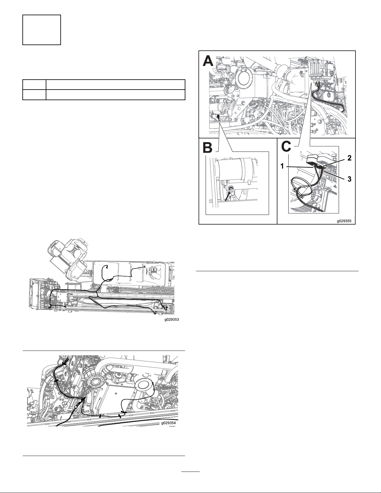
Figure15
Topviewofthemachinewiththewiringharness
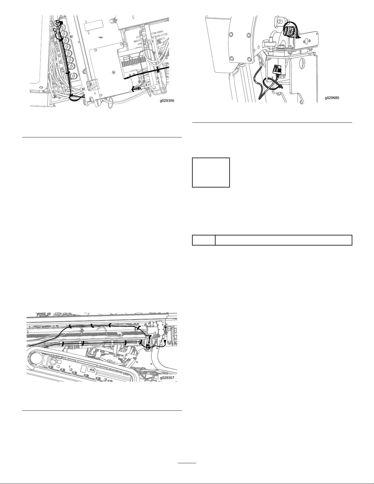
Figure16
Wiringharnesswithcableties
3.Routetheharnessleadmarkedstarteralongthewiring
harnessofthemachinestothestarterontheengine
andattachtheringterminaltothesamelocationasthe
currentwire(BoxBofFigure17).
1
2
3
g0293 55
A
BC
Figure17
Wiringharnesswithcableties
1.(colorandnumber)3.(colorandnumber)
2.(colorandnumber)
4.RoutethewiresmarkedasControllerApins8(red
wire),9(blackwire),and14(pinkwire)towardthe
stackofcontrollersasshowninBoxCofFigure17.
Note:Thecontrollerclosesttothemountingplate
shouldbeControllerA.Installthe3wiresintothe
properlocationsasindicatedonthetag.Thewire
sideoftheconnectorshasnumbersforreferenceto
locations.Thelocationshavearedsealpluginthehole
thatyouneedtoremovebeforeyoucaninstallthewire.
Inserttheterminaluntilthecontactclicksandlocks.
Pullslightlyonthewiretomakesurethatitisproperly
locked.Turntheconnectoroverandvisuallyinspectto
ensurethatterminalislockedalltheway.
5.Routetheremainingharnesstowardthethrustframe,
followingtheexistingharnessrouting(Figure15).
6.RoutethewiresmarkedasSetupValveandPipeLoader
(Front)forwardfromofthemachinefollowingthe
existingharnessrouting.
Note:Youshouldendupontheoutsideofthe
machineasshowninFigure18.
8

Figure18
Wiringharnesswithcableties
7.RoutetheconnectorsmarkedSetupValveuptothe
9-sectionvalveblocktothetopsolenoidmarkedSetup
Valve(Figure18).
8.Disconnecttheconnectorfromthetopsolenoidvalve
andplugitintothematingconnectoronthenew
harness.
9.Plugtheotherconnectorintothevalveyoupreviously
disconnected.
10.Locatetheroundconnectorontheexistingharness
thatwaspreviouslyconnectedtotheproximitysensor
(Figure18).
11.Unscrewtheconnector,removethecabletiessecuring
thiswire,andattachtheexistingconnectortothe
connectoronthenewharness(Figure18).
12.Routetheremainderofthenewharnessalongthe
existingharnessunderthethrustframe(Figure15).
13.RoutethewireswiththeRotarySensorconnector
alongthethrustframewiththeexistingharnesstoward
therearofthemachineandcontinuetoroutethe
harnessalongthehydrauliclinesasshowninFigure19.
Figure19
Wiringharnesswithcableties
14.Connecttheconnectorstotheproximitysensorand
therotarysensor(Figure19).
Note:Securethewiringharnesstothemachineas
showninFigure20.
Figure20
15.Installthelatestversionofsoftwareintothemachine
andcompletethetestsdescribedinthatsoftware
update.
4
RemovingtheRotaryPump
SupplyandDrainOrices
Partsneededforthisprocedure:
1Gasket
RemovingtheRotaryPumpSupplyand
DrainOrices
Important:Allowtheenginetocool.
1.Placeaoilpanunderthemachinetocatchoilfrom
therotarypump.
2.Removeandplugthecasedrainlinefromtherotary
pumpandcapoffthecasedrainttingtominimize
hydraulicuidloss.
9

Figure21
1.Removethesebolts2.Capoffthecase-drainline
3.Cleantheexternalsurfaceoftherotarypump.
4.Unplugthewiringharnessfromthepumpcontrol.
5.Removethe6boltsasshowninFigure21.
6.Removethecontrolfromthepumphousing.
Note:Oilwilldrainfromthecasewhenthehousing
isremoved.
7.Useneedlenoseplierstopulltheretainingclip(T40)
fromthecontrol(Figure22).
123g029477
Figure22
1.T50orice3.T60orice
2.T40,T30,andT20orices
8.Removethespring(T30)andsupplyorice(T20)from
thecontrol(Figure22).
9.Removethedrainorices(T50andT60)fromthe
controlhousing(Figure22).
10.Cleanthesealingsurfacesofthepumphousingand
controlhousing.
11.Installthecontrolhousingontothepumpusingthe
newgasket.
Important:Thecontrollinkagepinonthecontrol
mustbeinsertedintotheswash-platelinkinthe
pump.
Note:Usepetroleumjellytohelpholdtheswash-plate
linkinplacewhilethecontrolisinstalled.
Important:DonotuseRTVsealant.RTVsealant
candamagethepump.
Note:Therewillberesistancewhenthefrontedge
ofthecontrolistiltedawayfromthepumphousingif
thecontrollinkagepinisinsertedintotheswash-plate
linkcorrectly.
Note:Ifthecontrollinkagepinisnotproperly
insertedintotheswash-platelink,thepumpwillnot
returntoneutralandtherotarymotorwillspinupon
enginestartup.
12.Installthe6retainingbolts;torquetheboltsto16N-m
(12lb-ft).
13.Connectthecasedrainlineandcheckthehydraulic
uidlevel;refertotheOperator’sManualforthemachine.
14.Connectthewiringharnesstotherotarypumpcontrol.
15.Wipeupanyspilledoil.
16.Startthemachinetotesttherotarypump.
Important:Iftherotaryoutputspinswhenthe
machineisstartedbuttherotationcommandis
notgiven,thecontrollinkagepinisnotproperly
insertedintotheswash-platelink.Removeand
capthecasedrainlineandrepeattheabovesteps.
10

CheckingtheNeutralAdjustment
1.Installahydraulictestportanda1000psigaugeineach
ofthedisplacementcontrolports(M4andM5).
Figure23
1.M72port(adjustingscrew)3.M5port(displacement
controlport)
2.M90port(locknut)4.M4port(displacement
controlport)
2.Disconnecttheelectricalconnectorfromtherotary
pumpcontrol,startthemachine,andbringittohigh
idle.
3.Loosenthelocknut(M90)witha10mmand13mm
hexwrench.
4.Usinga3mmor4mminternalhexwrench,rotate
theadjustingscrew(M72)clockwiseuntilthepressure
increasesinoneofthepressuregauges.
Note:Notetheangularpositionofthewrench.
5.Rotatetheneutraladjustingscrewcounterclockwise
untilthepressureincreasesbyanequalamountonthe
othergauge.
Note:Notethepositionofthewrench.
6.Rotatetheadjustingscrew(M72)clockwisehalfthe
distancebetweenthelocationnotedinstep(4or5).
Note:Thegaugesshouldreadthesamepressure(case
pressure),indicatingthatthecontrolisinitsneutral
position.
7.Holdtheneutral-adjustingscrewstationaryandtighten
thelocknutto7N-m(62lb-in)forthe6mmscrewor
13N-m(120lb-in)forthe8mmscrew .
8.Oncetheneutralpositionisset,stoptheengine,
removethegauges,andremovethegaugeports.
9.Connecttheelectricalconnectortotherotarypump
control.
5
InstallingtheThrustMotor
Anti-RotationSupports
Partsneededforthisprocedure:
4Adjustmentblock
4Brace
8Nut(3/8-16inch)
4Bolt(3/8-16x11/4inch)
4Bolt(3/8-16x1inch)
8Spacer
8Washer
8Bolt(M12-13/4x70mm)
Procedure
RefertolocationhighlightedinFigure24forthisprocedure.
Figure24
Important:Ensurethatthereisnoweldingorweld
spatteraroundthreadedholesoronthemotormount
surfaces.
Cleanoffthepaint,oil,and/orrustfromtheweldingarea.
1.Weldtheadjustmentblocktothecarriageassemblyas
showninFigure25,Figure26,Figure27,Figure28,
andFigure29.
11

Figure25
Sideview
Figure26
TopView–Rearmounts(motorsremoved)
1.Weldtheblocks3/4inchesawayfromtheedges.
Figure27
TopView–Frontmounts(motorsremoved)
1.Weldtheblocks3/4inchesawayfromtheedges.
Figure28
SideView–Frontmounts(motorsremoved)
1.Weldthefrontmotorblocks1/8inchovertheedge.
Figure29
SideView–RearMounts(Alignedwiththeedge;motors
removed)
2.Removeanddiscardtheexistingboltandwasherfrom
thethrustmotor(BoxAofFigure30).
12

Figure30
1.Brace
2.Bolt(M12)
3.Washer
4.Spacer
5.Nut(3/8-16inch)
6.Bolt(3/8-16x11/4inch)rearmotorassemblies
7.Bolt(3/8-16x1inch)frontmotorassemblies
3.Liftthethrustmotorandinstallthebracesupports
(BoxBofFigure30).
Note:Themotorbraceshouldbecenteredonthe
thrust-motorange.
Note:Loosenthettingsonthethrust-motorttings,
ifnecessary.
4.Applythread-lockingcompoundtothe8bolts(M12)
andlooselyinstallthebolts,washers,andspacersinto
thethrustmotorassembly(BoxCofFigure30).
5.Installthenutsonthebolts,applythread-locking
compoundtothe4bolts(3/8-16x11/4inch),and
installtheassemblyintotherearmotorassembly(Box
DofFigure30).
6.Installthenutsonthebolts,applythread-locking
compoundtothe4bolts(3/8-16x1inch),andinstall
theassemblyintothefrontmotorassembly(BoxEof
Figure30).
7.Placethemotorbracecenteredagainstthethrust
motorangeandalternatelytightentheadjustment
bolts(3/8-16)to37toN-m(27to33ft-lb).
8.Tightenthejamnutsagainsttheadjustmentblocks.
9.Torquethe8bolts(M12)to90to112N-m(67to83
ft-lb).
10.Painttheweldedarea.
6
InstallingtheProximitySwitch
Bracket
Partsneededforthisprocedure:
1Bracket
1Plateag
4Bolt(M5-0.08x25mm)
4Nut(M5)
2Cabletie
Procedure
Cleanoffthepaint,oil,and/orrustfromtheweldingarea.
1.Placethebracket3inchesawayfromtherodbox
mountingplateand13/4inchesawayfromthebottom
ofthecarriageweldmenttothetopofthebracketand
weldthebrackettothethrustframe(Figure31and
Figure32).
Figure31
1.13/4-inchgap3.Bracket
2.3-inchgap
13

Figure32
2.Weldtheplateagtothecarriageassembly57/8
inchesawayfromthespindleendofthecarriage
assemblyasshowninFigure33.
Figure33
1.57/8-inchgap2.Plateag
3.Painttheweldedarea.
4.Disconnectthewiringharnessontheexistingrear
sensor(Figure34)androutethewiringharnessthrough
theholesonthebracketasshowninFigure35.
Figure34
Currentrouting
Figure35
Existingrearsensor
1.Existingsensor
5.Tagthesensorandwiringharnesstonotewhichpart
oftheharnessgoestowhichsensor(Figure36).
6.Disconnectthewiringharnessfromthe2proximity
switches(Figure36).
Figure36
1.Pipe-breakoutsensor2.Pipe-returnsensor
14

7.Removethe2proximitysensorsfromthemounting
plateanddiscardthehardware(Figure36).
8.Looselysecurethe2proximitysensorstothebracket
with4bolts(M5)and4nuts(M5)asshowninFigure
37.
Figure37
1.Bolt(M5)4.Pipe-breakoutproximity
sensor
2.Proximitysensor5.Pipe-returnproximity
sensor
3.Nut(M5)
9.RoutethewiringharnessasshowninFigure38,
andconnecttheproperconnectionstotheproper
proximitysensors.
Note:Ensurethattheharnessdoesnotinterferewith
anyhotormovingparts.
Figure38
10.Securetheexcessamountofthewiringharnesswitha
cabletie.
11.Use2(ormore)peopletoadjusttheproximityswitches:
Important:Ensurethatthegearboxiscompletely
forwardinthecarriageweldment.
Pipe-BreakoutSensor
A.Pullthedrillpipeandleadbarbackthroughthe
pipeguideandintothewrenchesuntilthepipe
jointisinthemiddleofthewrenches(Figure39).
Figure39
1.Rearwrench3.Frontwrench
2.Centerofthewrenches
B.Adjustthepipe-breakoutproximitysensoruntil
thelightilluminates(Figure40).
Figure40
1.Pipe-breakoutlight2.Pipe-returnlight
C.Tightentheboltsandnutsonthesensor.
D.Torquetheboltsto791to971N-cm(70to86
in-lb).
Pipe-ReturnSensor
A.Pullthedrillpipeandleadbarthroughthepipe
guideandthroughthewrenchesuntilthefrontof
thepipeislinedupwiththefrontoftherodbox
(Figure41).
15

Figure41
1.Rearbracket2.Frontbracket
B.Adjustthepipe-returnproximitysensoruntilthe
lightilluminates(Figure40).
C.Tightentheboltsandnutsonthesensor.
D.Torquetheboltsto791to971N-cm(70to86
in-lb).
7
InstallingtheCapsandDecal
Partsneededforthisprocedure:
1Valvecap
1Monitorcap
1Decal
Procedure
InstallthedecalasshowninFigure42.
Figure42
1.Decal
Removethemanualoverridevalvescrewandinstallthevalve
capasshowninFigure43.
Figure43
1.Valvecap2.Manual-overridevalve
Gentlyliftthemonitorawayfromtheconsoleusingaat
headscrewdriverinthegapsasshowninBoxAofFigure44.
Figure44
1.Gapsbetweenthemonitorandconsolepanel
Insertthemonitorcapintotheportonthebackofthe
monitorandinstallthemonitorbackontotheconsole(Box
BofFigure44).
Connectthepositiveterminalofthebatterythenconnect
thenegativeterminal.
16
Table of contents
Other Toro Power Tools Accessories manuals
Popular Power Tools Accessories manuals by other brands

Steelman
Steelman SH-047 Operator's manual

Forstreich Maschinenbau
Forstreich Maschinenbau TR24-AQ operating instructions

Milwaukee
Milwaukee DEG 125 Original instructions

Matatakitoyo Torque Tools
Matatakitoyo Torque Tools MT2-4500N Operation manual

Matatakitoyo Torque Tools
Matatakitoyo Torque Tools MT2-4000N Operation manual

Kitagawa
Kitagawa HG-A97-212 instruction manual